EP0089450A2 - Device for the transverse cutting of movable sheet metal strip - Google Patents
Device for the transverse cutting of movable sheet metal strip Download PDFInfo
- Publication number
- EP0089450A2 EP0089450A2 EP82890184A EP82890184A EP0089450A2 EP 0089450 A2 EP0089450 A2 EP 0089450A2 EP 82890184 A EP82890184 A EP 82890184A EP 82890184 A EP82890184 A EP 82890184A EP 0089450 A2 EP0089450 A2 EP 0089450A2
- Authority
- EP
- European Patent Office
- Prior art keywords
- crankshaft
- frame
- knife
- sheet metal
- oscillating frame
- Prior art date
- Legal status (The legal status is an assumption and is not a legal conclusion. Google has not performed a legal analysis and makes no representation as to the accuracy of the status listed.)
- Ceased
Links
Images


Classifications
-
- B—PERFORMING OPERATIONS; TRANSPORTING
- B23—MACHINE TOOLS; METAL-WORKING NOT OTHERWISE PROVIDED FOR
- B23D—PLANING; SLOTTING; SHEARING; BROACHING; SAWING; FILING; SCRAPING; LIKE OPERATIONS FOR WORKING METAL BY REMOVING MATERIAL, NOT OTHERWISE PROVIDED FOR
- B23D25/00—Machines or arrangements for shearing stock while the latter is travelling otherwise than in the direction of the cut
- B23D25/02—Flying shearing machines
- B23D25/06—Flying shearing machines having a cutting device mounted on an oscillating lever
Definitions
- the invention relates to a device for cross-dividing moving sheet metal strips, consisting of a swing frame mounted on a crankshaft, which is supported on a link which is articulated at a distance from the crankshaft on the swing frame and runs transversely to the crankshaft, and a slidably guided in the swing frame a thrust crank drive, which cooperates with a frame-fixed counter knife.
- the swing frame is raised and lowered over the crankshaft and at the same time driven back and forth via the link articulated on the swing frame by a crank mechanism, so that the frame-fixed knife not only against metal strip to be cut is lowered, but is also moved in the running direction of the metal strip during the cutting movement.
- the knife which is slidably guided in the oscillating frame, is driven in opposite directions by an angularly offset crank of the crankshaft for the oscillating frame and the sheet metal strip is cut during its movement.
- a disadvantage of these known devices is first of all that the cutting speed depends on the swiveling speed of the oscillating frame and thus on the throughput speed of the workpiece to be cut, because in order to match the knife movement to the swiveling movement of the oscillating frame, the crankshaft for the oscillating frame and the crank mechanism for the swiveling movement of the oscillating frame must be coupled.
- This coupling for example, by a drive connection is produced, in turn, does not allow the use of such a device for cutting stationary sheet metal strips, unless a phase shift is achieved between the two drives, which enables an approximately straight up and down movement of the oscillating frame.
- crank mechanism for the pivoting movement of the oscillating frame must be rotated with respect to the crankshaft of the oscillating frame, which increases the design effort, which is already considerable due to the separate pivoting drive, by means of a corresponding coupling device.
- mass to be moved for a cut is comparatively large, so that appropriately dimensioned drives must be provided.
- the invention is therefore based on the object to avoid these deficiencies and to improve a device for cross-dividing moving metal strips of the type described above so that the cutting speed can be selected independently of the throughput speed of the strip with simple design means and a problem-free conversion to cuts not moving belt is guaranteed.
- a simple coordination of the pivoting movement of the oscillating frame to the position of the frame-fixed counter knife on the sheet metal strip to be divided is to be ensured.
- the invention achieves the stated object in that the link articulated on the oscillating frame is mounted in a stationary manner and that crankshafts which can be driven are provided for the oscillating frame and the push crank mechanism.
- the oscillating frame Due to the fixed mounting of the link articulated on the oscillating frame, the oscillating frame is also oscillatingly driven by the crankshaft for the up and down movement, the oscillation distance and thus also the speed of the pivoting movement from the distance of the Handlebar linkage on the swing frame depends on the crankshaft axis.
- This forced coupling of the swivel drive with the up and down movement of the swing frame brings with it the advantage of a simple design without an additional swivel drive, but this measure alone cannot avoid the disadvantages of the known designs with regard to the dependence of the cutting speed on the swing frame drive.
- crankshafts for the oscillating frame and for the thrust crank drive would not be necessary, such a coaxial crankshaft arrangement results in particularly simple and space-saving design conditions, in particular when the hollow crankshaft for the oscillating frame is mounted on the crankshaft of the push crank drive.
- the oscillating frame 1 of a device for cross-dividing moving sheet metal strips is mounted on a crankshaft 2, which consists of two hollow sections and is rotatably mounted on a crankshaft 3, which is mounted on push rods 4 drives a knife bar 5 which is guided in the oscillating frame 1 so as to be displaceable.
- the oscillating frame 1 is guided by a link 6 which is articulated at a distance from the crankshaft 2 on the oscillating frame 1 and which is held pivotably in a fixed bearing 7.
- crankshaft 2 is driven by a motor 8, which is connected to the two sections 2 of the crankshaft via a gear 9 and a connecting shaft 10, the oscillating frame 1 is not only raised and lowered by the crankshaft 2, but also because of the Guide pivoted back and forth by the handlebar 6, so that the frame-fixed counter knife 11 is not only placed against the sheet metal strip passing through the oscillating frame 1, but is also moved with the moving sheet metal strip in its direction of movement.
- the knife bar 5 with the knife 12 is displaced with respect to the oscillating frame 1 by means of the thrust crank mechanism consisting of the crankshaft 3 and the push rods 4, and the desired cut is carried out, after which the knife 12 is removed from the thrust crank mechanism 3, 4 withdrawn and the counter knife 11 is lifted through the frame from the cut band and pivoted back into the starting position.
- the possibility of driving the knife 12, which is independent of the oscillating frame drive, offers the decisive advantage that the cutting speed can be selected independently of the belt throughput speed.
- crankshaft 3 of the slider crank mechanism which with the help of bearings 13 and 14 in a frame is mounted, the bearings 14 comprising the sections of the crankshaft 2 mounted on the crankshaft 3 is driven by a flywheel 15 which is freely rotatable on the crankshaft 3 and can be connected to the latter via a clutch 16.
- This clutch 16 is designed so that the crankshaft 3 is braked by the flywheel when uncoupled.
- a frame 17 is provided in the constructive embodiment of a device according to the invention, on which the individual structural parts are mounted ...
- the oscillating frame 1 is not only the one that can be driven by itself, with the push rods 4 of the push crank drive connected knife bar 5 slidably guided, but also a sheet metal holder 18 which cooperates with a frame-mounted counter-holder 19.
- This sheet metal holder 18 has lateral guide strips 20 which engage between guide rollers 21, as can be seen in particular in FIG. 6.
- This sheet holder 18 is driven by a pair of push rods 22, which are mounted on the sections of the crankshaft 2 with the aid of bearings 23 and hold the sheet holder 18 when the swinging frame sinks during the positioning movement, so that the sheet holder 18 holds the sheet metal strip from below against the counter holder 19 presses.
- the sheet metal strip to be cut is consequently tensioned in the cutting area in line with the cut.
- the swing frame 1 To guide the cutter bar 5 in the swing frame 1, the swing frame 1 has two guide tracks 24 on both sides of the cutter bar 5, on which rollers 25 of the cutter bar 5 roll. Since the guide tracks 24 can be adjusted in their distance from one another by means of an actuating drive, for example a screw drive 26, a largely play-free guidance of the cutter bar 5 in the oscillating frame 1 is possible, which makes the cut quality of course influenced.
- an actuating drive for example a screw drive 26
- a motor 27 is used to drive the flywheel 15, which is flanged to the frame 17 and is in drive connection with the flywheel 15 via V-belts 28. Since only the knife bar 5 with the knife 12 has to be driven via the motor 27, the mass to be accelerated remains comparatively small, so that a high acceleration and thus a quick cut can be ensured via the flywheel 15, with a comparatively small motor output.
- the motor 27 can run continuously.
- crankshaft 2 shows the mounting of a section of the crankshaft 2 for the oscillating frame 1 on the crankshaft 3 for driving the cutter bar 5.
- the crank of the crankshaft 2 is formed by an eccentric 29 on which the oscillating frame 1 is supported via bearings 30.
- the crankshaft 2 is driven from the connecting shaft 10 via a gear 31 which meshes with a counter gear 32.
- This counter wheel 32 is rotatably connected to the crankshaft 2, which is supported in the bearings 13 and 14 relative to the frame and carries the bearings for the crankshaft 3.
Abstract
Description
Die Erfindung bezieht sich auf eine Vorrichtung zum Querteilen bewegter Blechbänder, bestehend aus einem auf einer Kurbelwelle gelagerten Schwingrahmen, der an einem mit Abstand von der Kurbelwelle am Schwingrahmen angelenkten, quer zur Kurbelwelle verlaufenden Lenker abgestützt ist, und aus einem im Schwingrahmen verschiebbar geführten, durch einen Schubkurbeltrieb antreibbaren, mit einem rahmenfesten Gegenmesser zusammenwirkenden Messer.The invention relates to a device for cross-dividing moving sheet metal strips, consisting of a swing frame mounted on a crankshaft, which is supported on a link which is articulated at a distance from the crankshaft on the swing frame and runs transversely to the crankshaft, and a slidably guided in the swing frame a thrust crank drive, which cooperates with a frame-fixed counter knife.
Bei einer bekannten Vorrichtung dieser Art (DE-OS 30 36 621) wird der Schwingrahmen über die Kurbelwelle gehoben und gesenkt und gleichzeitig über den am Schwingrahmen angelenkten Lenker von einem Kurbeltrieb her hin- und hergehend angetrieben, so daß das rahmenfeste Messer nicht nur gegen das zu schneidende Blechband abgesenkt, sondern auch in der Laufrichtung des Blechbandes während der Schnittbewegung mitbewegt wird. Das im Schwingrahmen verschiebbar geführte Messer wird dabei durch eine winkelversetzte Kurbel der Kurbelwelle für den Schwingrahmen gegensinnig angetrieben und das Blechband während seiner Bewegung geschnitten. Nachteilig bei diesen bekannten Vorrichtungen ist zunächst, daß die Schnittgeschwindigkeit von der Schwenkgeschwindigkeit des Schwingrahmens und damit von der Durchlaufgeschwindigkeit des zu schneidenden Werkstückes abhängt, weil zur Abstimmung der Messerbewegung auf die Schwenkbewegung des Schwingrahmens die Kurbelwelle für den Schwingrahmen und der Kurbeltrieb für die Schwenkbewegung des Schwingrahmens gekoppelt sein müssen. Diese Koppelung, die beispielsweise durch eine Antriebsverbindung hergestellt wird, läßt wiederum den Einsatz einer solchen Vorrichtung für das Schneiden unbewegter Blechbänder nicht zu, wenn nicht zwischen den beiden Antrieben eine Phasenverschiebung erreicht wird, die eine angenähert geradlinige Auf- und Abbewegung des Schwingrahmens ermöglicht. Zu diesem Zweck muß der Kurbeltrieb für die Schwenkbewegung des Schwingrahmens gegenüber der Kurbelwelle des Schwingrahmens verdreht werden, was den durch den gesonderten Schwenkantrieb bereits erheblichen Konstruktionsaufwand noch durch eine entsprechende Kupplungseinrichtung vermehrt. Abgesehen davon ist die für einen Schnitt zu bewegende Masse vergleichsweise groß, so daß entsprechend dimensionierte Antriebe vorgesehen werden müssen.In a known device of this type (DE-OS 30 36 621), the swing frame is raised and lowered over the crankshaft and at the same time driven back and forth via the link articulated on the swing frame by a crank mechanism, so that the frame-fixed knife not only against metal strip to be cut is lowered, but is also moved in the running direction of the metal strip during the cutting movement. The knife, which is slidably guided in the oscillating frame, is driven in opposite directions by an angularly offset crank of the crankshaft for the oscillating frame and the sheet metal strip is cut during its movement. A disadvantage of these known devices is first of all that the cutting speed depends on the swiveling speed of the oscillating frame and thus on the throughput speed of the workpiece to be cut, because in order to match the knife movement to the swiveling movement of the oscillating frame, the crankshaft for the oscillating frame and the crank mechanism for the swiveling movement of the oscillating frame must be coupled. This coupling, for example, by a drive connection is produced, in turn, does not allow the use of such a device for cutting stationary sheet metal strips, unless a phase shift is achieved between the two drives, which enables an approximately straight up and down movement of the oscillating frame. For this purpose, the crank mechanism for the pivoting movement of the oscillating frame must be rotated with respect to the crankshaft of the oscillating frame, which increases the design effort, which is already considerable due to the separate pivoting drive, by means of a corresponding coupling device. Apart from this, the mass to be moved for a cut is comparatively large, so that appropriately dimensioned drives must be provided.
Der Erfindung liegt somit die Aufgabe zugrunde, diese Mängel zu vermeiden und eine Vorrichtung zum Querteilen bewegter Blechbänder der eingangs geschilderten Art so zu verbessern, daß mit einfachen konstruktiven Mitteln die Schnittgeschwindigkeit unabhängig von der Durchlaufgeschwindigkeit des Bandes gewählt werden kann und eine problemlose Umstellung auf Schnitte bei nicht bewegtem Band gewährleistet wird. Außerdem soll eine einfache Abstimmung der Schwenkbewegung des Schwingrahmens auf die Anstellung des rahmenfesten Gegenmessers an das zu teilende Blechband sichergestellt werden.The invention is therefore based on the object to avoid these deficiencies and to improve a device for cross-dividing moving metal strips of the type described above so that the cutting speed can be selected independently of the throughput speed of the strip with simple design means and a problem-free conversion to cuts not moving belt is guaranteed. In addition, a simple coordination of the pivoting movement of the oscillating frame to the position of the frame-fixed counter knife on the sheet metal strip to be divided is to be ensured.
Die Erfindung löst die gestellte Aufgabe dadurch, daß der am Schwingrahmen angelenkte Lenker ortsfest gelagert ist und daß für den Schwingrahmen und den Schubkurbeltrieb je für sich antreibbare Kurbelwellen vorgesehen sind.The invention achieves the stated object in that the link articulated on the oscillating frame is mounted in a stationary manner and that crankshafts which can be driven are provided for the oscillating frame and the push crank mechanism.
Durch die ortsfeste Lagerung des am Schwingrahmen angelenkten Lenkers wird der Schwingrahmen durch die Kurbelwelle für die Auf- und Abbewegung auch schwingend angetrieben, wobei die Schwingweite und damit auch die Geschwindigkeit der Schwenkbewegung vom Abstand der Lenkeranlenkung am Schwingrahmen von der Kurbelwellenachse abhängt. Diese zwangsweise Koppelung des Schwenkantriebes mit der Auf- und Abbewegung des Schwingrahmens bringt zwar den Vorteil einer einfachen Konstruktion ohne zusätzlichen Schwenkantrieb mit sich, doch kann diese Maßnahme allein die Nachteile der bekannten Konstruktionen hinsichtlich der Abhängigkeit der Schnittgeschwindigkeit vom Schwingrahmenantrieb nicht vermeiden. Erst durch die erfindungsgemäße Trennung der Antriebe für den Schwingrahmen und für die am beweglichen Messer angreifende Schubkurbel kann eine gegenüber der Schwingrahmenbewegung hohe Schnittgeschwindigkeit gewährleistet werden, die während des Schnittes eine geringere Änderung des von der Schwenklage des Schwingrahmens abhängigen Anstellwinkels des Messers und damit sauberere Schnittkanten zur Folge hat. Da über den Schubkurbeltrieb lediglich das verschiebbar im Schwingrahmen geführte Messer angetrieben wird, bleiben die vom Schubkurbeltrieb zu beschleunigenden Massen vergleichsweise klein, so daß mit geringeren Antriebsleistungen höhere Schnittgeschwindigkeiten erreicht werden können.Due to the fixed mounting of the link articulated on the oscillating frame, the oscillating frame is also oscillatingly driven by the crankshaft for the up and down movement, the oscillation distance and thus also the speed of the pivoting movement from the distance of the Handlebar linkage on the swing frame depends on the crankshaft axis. This forced coupling of the swivel drive with the up and down movement of the swing frame brings with it the advantage of a simple design without an additional swivel drive, but this measure alone cannot avoid the disadvantages of the known designs with regard to the dependence of the cutting speed on the swing frame drive. It is only through the separation of the drives for the oscillating frame and for the thrust crank acting on the movable knife that a cutting speed that is high compared to the oscillating frame movement can be guaranteed, which during the cut will result in a smaller change in the angle of attack of the knife dependent on the pivoting position of the oscillating frame and thus cleaner cutting edges Consequence. Since only the knife, which is slidably guided in the oscillating frame, is driven via the thrust crank drive, the masses to be accelerated by the push crank drive remain comparatively small, so that higher cutting speeds can be achieved with lower drive powers.
Obwohl eine koaxiale Anordnung der Kurbelwellen für den Schwingrahmen und für den Schubkurbeltrieb nicht erforderlich wäre, ergeben sich durch eine solche koaxiale Kurbelwellenanordnung besonders einfache und platzsparende Konstruktionsverhältnisse, insbesondere dann, wenn die hohl ausgebildete Kurbelwelle für den Schwingrahmen auf der Kurbelwelle des Schubkurbeltriebes gelagert ist.Although a coaxial arrangement of the crankshafts for the oscillating frame and for the thrust crank drive would not be necessary, such a coaxial crankshaft arrangement results in particularly simple and space-saving design conditions, in particular when the hollow crankshaft for the oscillating frame is mounted on the crankshaft of the push crank drive.
Da die durch den Schubkurbeltrieb für das verschiebbar im Schwingrahmen geführte Messer zu beschleunigenden Massen vergleichsweise klein sind, wird es in weiterer Ausbildung der Erfindung möglich, die Kurbelwelle des Schubkurbeltriebes über ein Schwungrad und eine Kupplung anzutreiben. Ein solcher Antrieb hat den bedeutenden Vorteil, daß mit einem Motor vergleichbar kleiner Leistung das Auslangen gefunden werden kann, weil dieser Motor ständig laufen kann und die im Schwungrad gespeicherte Energie bei der Kupplung der Kurbelwelle mit dem Schwungrad die Beschleunigung des beweglichen Messers für die Schnittbewegung unterstützt. Mit Hilfe einer mit der Kupplung kombinierten Bremse kann das bewegliche Messer nach dem Schnitt wieder in einer gewünschten Lage festgehalten werden.Since the masses to be accelerated by the thrust crank drive for the knife slidably guided in the oscillating frame are comparatively small, it is possible in a further embodiment of the invention to drive the crank shaft of the thrust crank drive via a flywheel and a clutch. Such a drive has the significant advantage that with a motor comparably less power sufficiency can be found because this engine can run continuously and the energy stored in the flywheel when coupling the crankshaft with the flywheel supports the acceleration of the movable knife for the cutting movement. With the help of a brake combined with the coupling, the movable knife can be held in a desired position again after the cut.
Durch den gesonderten Antrieb der Kurbelwellen für den Schwingrahmen und für den Schubkurbeltrieb werden somit für den Schnitt besonders günstige Verhältnisse geschaffen, die auch ein einfaches Umstellen auf das Teilen unbewegter Bänder zulassen. Nach dem Anstellen des rahmenfesten Gegenmessers an das ruhende Band über eine entsprechende Schwingrahmenbewegung kann bei stehendem Schwingrahmen der Schnitt über das für sich antreibbare, im Schwingrahmen verschiebbar geführte Messer ohne Relativbewegung des Schwingrahmens gegenüber dem Band durchgeführt werden.Due to the separate drive of the crankshafts for the oscillating frame and for the thrust crank drive, particularly favorable conditions are created for the cut, which also allow a simple changeover to the division of unmoving belts. After the frame-fixed counter knife has been placed against the stationary belt by means of a corresponding oscillating frame movement, the cut can be carried out with the oscillating frame at a standstill by means of the knife which can be driven and is displaceably guided in the oscillating frame without any relative movement of the oscillating frame with respect to the belt.
In der Zeichnung ist der Erfindungsgegenstand beispielsweise dargestellt. Es zeigen
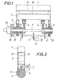
- Fig. 1 eine erfindungsgemäße Vorrichtung zum Querteilen bewegter Blechbänder in einem schematischen Längsschnitt,
- Fig. 2 diese Vorrichtung in einem Querschnitt,
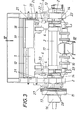
- Fig. 3 eine konstruktive Ausführung einer erfindungsgemäßen Vorrichtung in Ansicht von vorne,
- Fig. 4 einen Schnitt nach der Linie IV-IV der Fig. 3 in einem größeren Maßstab,
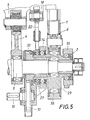
- Fig. 5 die Anordnung der Kurbelwellen für den Schwingrahmen und den Schubkurbeltrieb für das bewegliche Messer in einem Axialschnitt in einem größeren Maßstab und
- Fig. 6 einen Querschnitt durch die Führung des beweglichen Messers im Schwingrahmen.
- 1 shows a device according to the invention for cross-dividing moving metal strips in a schematic longitudinal section,
- 2 this device in a cross section,
- 3 shows a constructive embodiment of a device according to the invention in a view from the front,
- 4 shows a section along the line IV-IV of FIG. 3 on a larger scale,
- Fig. 5 shows the arrangement of the crankshafts for the swing frame and the thrust crank mechanism for the movable knife in an axial section on a larger scale and
- Fig. 6 shows a cross section through the leadership of the movable knife in the swing frame.
Wie insbesondere der schematischen Darstellung nach den Fig. 1 und 2 entnommen werden kann, ist der Schwingrahmen 1 einer Vorrichtung zum Querteilen bewegter Blechbänder auf einer Kurbelwelle 2 gelagert, die aus zwei hohlen Teilstücken besteht und drehbar auf einer Kurbelwelle 3 gelagert ist, die über Schubstangen 4 einen im Schwingrahmen 1 verschiebbar geführten Messerbalken 5 antreibt. Der Schwingrahmen 1 wird dabei durch einen mit Abstand von der Kurbelwelle 2 am Schwingrahmen 1 angelenkten Lenker 6 geführt, der in einem ortsfesten Lager 7 schwenkbar gehalten ist. Wird die Kurbelwelle 2 durch einen Motor 8 angetrieben, der über ein Getriebe 9 und eine Verbindungswelle 10 mit den beiden Teilstücken 2 der Kurbelwelle in Verbindung steht, so wird der Schwingrahmen 1 durch die Kurbelwelle 2 nicht nur gehoben und gesenkt, sondern auch auf Grund der Führung durch den Lenker 6 hin- und hergeschwenkt, so daß das rahmenfeste Gegenmesser 11 nicht nur an das durch den Schwingrahmen 1 durchlaufende Blechband angestellt, sondern auch mit dem bewegten Blechband in dessen Bewegungsrichtung mitbewegt wird. Während dieser gleichsinnigen Bewegung des angestellten Gegenmessers 11 und des Bandes wird der Messerbalken 5 mit dem Messer 12 über den aus der Kurbelwelle 3 und den Schubstangen 4 bestehenden Schubkurbeltrieb gegenüber dem Schwingrahmen 1 verschoben und der gewünschte Schnitt durchgeführt, wonach das Messer 12 vom Schubkurbeltrieb 3, 4 zurückgezogen und das Gegenmesser 11 durch den Rahmen vom geschnittenen Band abgehoben und in die Ausgangslage zurückgeschwenkt wird. Die vom Schwingrahmenantrieb unabhängige Antriebsmöglichkeit des Messers 12 bietet dabei den entscheidenden Vorteil, daß die Schnittgeschwindigkeit für sich unabhängig von der Banddurchlaufgeschwindigkeit gewählt werden kann. Die Kurbelwelle 3 des Schubkurbeltriebes, die mit Hilfe von Lagern 13 und 14 in einem Gestell gelagert ist, wobei die Lager 14 die auf der Kurbelwelle 3 gelagerten Teilstücke der Kurbelwelle 2 umfassen, wird von einem Schwungrad 15 her angetrieben, das frei drehbar auf der Kurbelwelle 3 sitzt und mit dieser über eine Kupplung 16 verbunden werden kann. Diese Kupplung 16 ist dabei so ausgebildet, daß die Kurbelwelle 3 bei einer Entkupplung vom Schwungrad abgebremst wird.As can be seen in particular from the schematic representation according to FIGS. 1 and 2, the oscillating
Wie insbesondere die Fig. 3 und 4 zeigen, ist bei der konstruktiven Ausführung einer erfindungsgemäßen Vorrichtung ein Gestell 17 vorgesehen, auf dem die einzelnen Konstruktionsteile gelagert sind...Im Schwingrahmen 1 ist nicht nur der für sich antreibbare, mit den Schubstangen 4 des Schubkurbeltriebes verbundene Messerbalken 5 verschiebbar geführt, sondern auch ein Blechhalter 18, der mit einem rahmenfesten Gegenhalter 19 zusammenwirkt. Dieser Blechhalter 18 weist seitliche Führungsleisten 20 auf, die zwischen Führungsrollen 21 greifen, wie dies insbesondere der Fig. 6 entnommen werden kann. Zum Antrieb dieses Blechhalters 18 dient ein Schubstangenpaar 22, das auf den Teilstücken der Kurbelwelle 2 mit Hilfe von Lagern 23 gelagert ist und den Blechhalter 18 beim Absinken des Schwingrahmens während der Anstellbewegung festhält, so daß der Blechhalter 18 das Blechband von unten gegen den Gegenhalter 19 drückt. Das zu schneidende Blechband wird folglich im Schnittbereich schnittgerecht gespannt.3 and 4, in particular, a
Zur Führung des Messerbalkens 5 im Schwingrahmen 1 weist der Schwingrahmen 1 zu beiden Seiten des Messerbalkens 5 zwei Führungsbahnen 24 auf, auf denen Rollen 25 des Messerbalkens 5 abrollen. Da die Führungsbahnen 24 durch einen Stelltrieb, beispielsweise einen Schraubentrieb 26, in ihrem Abstand voneinander eingestellt werden können, ist eine weitgehend spielfreie Führung des Messerbalkens 5 im Schwingrahmen 1 möglich, was die Schnittqualität selbstverständlich beeinflußt.To guide the
Zum Antrieb des Schwungrades 15 dient ein Motor 27, der am Gestell 17 angeflanscht ist und über Keilriemen 28 mit dem Schwungrad 15 in Antriebsverbindung steht. Da über den Motor 27 lediglich der Messerbalken 5 mit dem Messer 12 angetrieben werden muß, bleibt die zu beschleunigende Masse vergleichsweise klein, so daß über das Schwungrad 15 eine hohe Beschleunigung und damit ein rascher Schnitt sichergestellt werden kann, und zwar bei vergleichsweise kleiner Motorleistung. Der Motor 27 kann ja kontinuierlich laufen.A
In der Fig. 5 ist die Lagerung eines Teilstückes der Kurbelwelle 2 für den Schwingrahmen 1 auf der Kurbelwelle 3 für den Antrieb des Messerbalkens 5 näher dargestellt. Die Kurbel der Kurbelwelle 2 wird durch einen Exzenter 29 gebildet, auf dem der Schwingrahmen 1 über Lager 30 abgestützt ist. Der Antrieb der Kurbelwelle 2 erfolgt von der Verbindungswelle 10 her über ein Zahnrad 31, das mit einem Gegenrad 32 kämmt. Dieses Gegenrad 32 ist drehfest mit der Kurbelwelle 2 verbunden, die in den Lagern 13 und 14 gegenüber dem Gestell abgestützt ist und die Lager für die Kurbelwelle 3 trägt. Es ergibt sich somit eine sehr kompakte Bauweise, die allen Verhältnissen Rechnung trägt.5 shows the mounting of a section of the
Claims (3)
Applications Claiming Priority (2)
| Application Number | Priority Date | Filing Date | Title |
|---|---|---|---|
| AT1120/82 | 1982-03-23 | ||
| AT112082A AT373523B (en) | 1982-03-23 | 1982-03-23 | DEVICE FOR CROSS-DIVIDING MOVING TAPES |
Publications (2)
| Publication Number | Publication Date |
|---|---|
| EP0089450A2 true EP0089450A2 (en) | 1983-09-28 |
| EP0089450A3 EP0089450A3 (en) | 1984-07-18 |
Family
ID=3507016
Family Applications (1)
| Application Number | Title | Priority Date | Filing Date |
|---|---|---|---|
| EP82890184A Ceased EP0089450A3 (en) | 1982-03-23 | 1982-12-15 | Device for the transverse cutting of movable sheet metal strip |
Country Status (3)
| Country | Link |
|---|---|
| EP (1) | EP0089450A3 (en) |
| JP (1) | JPS58171212A (en) |
| AT (1) | AT373523B (en) |
Cited By (2)
| Publication number | Priority date | Publication date | Assignee | Title |
|---|---|---|---|---|
| DE19847145C2 (en) * | 1997-10-13 | 2000-11-16 | Yazaki Corp | Connection plate for a battery holder |
| AU2014286268B2 (en) * | 2013-07-01 | 2019-02-28 | Csl Behring Ag | Process |
Families Citing this family (1)
| Publication number | Priority date | Publication date | Assignee | Title |
|---|---|---|---|---|
| DE4336626C2 (en) * | 1993-10-27 | 2002-04-04 | Sms Demag Ag | Scissors, especially cross-cut scissors |
Citations (5)
| Publication number | Priority date | Publication date | Assignee | Title |
|---|---|---|---|---|
| US2261007A (en) * | 1940-11-09 | 1941-10-28 | United Eng Foundry Co | Reciprocating flying shear |
| GB1137131A (en) * | 1965-01-11 | 1968-12-18 | United Eng Foundry Co | Shears |
| DE2027629A1 (en) * | 1969-06-13 | 1970-12-17 | Zdärske strojirny a slevärny, N.P., Zdär nad Sazavou (Tschechoslowakei) | Flying pendulum shears |
| JPS53146388A (en) * | 1977-05-27 | 1978-12-20 | Hitachi Ltd | Pendulum shearing machine |
| DE3036621A1 (en) * | 1979-09-29 | 1981-04-02 | Nippon Steel Corp., Tokyo | SWINGING, MOVING SCISSORS WITH STATIONARY SHEAR EFFECT |
-
1982
- 1982-03-23 AT AT112082A patent/AT373523B/en not_active IP Right Cessation
- 1982-12-15 EP EP82890184A patent/EP0089450A3/en not_active Ceased
-
1983
- 1983-03-23 JP JP4731983A patent/JPS58171212A/en active Pending
Patent Citations (5)
| Publication number | Priority date | Publication date | Assignee | Title |
|---|---|---|---|---|
| US2261007A (en) * | 1940-11-09 | 1941-10-28 | United Eng Foundry Co | Reciprocating flying shear |
| GB1137131A (en) * | 1965-01-11 | 1968-12-18 | United Eng Foundry Co | Shears |
| DE2027629A1 (en) * | 1969-06-13 | 1970-12-17 | Zdärske strojirny a slevärny, N.P., Zdär nad Sazavou (Tschechoslowakei) | Flying pendulum shears |
| JPS53146388A (en) * | 1977-05-27 | 1978-12-20 | Hitachi Ltd | Pendulum shearing machine |
| DE3036621A1 (en) * | 1979-09-29 | 1981-04-02 | Nippon Steel Corp., Tokyo | SWINGING, MOVING SCISSORS WITH STATIONARY SHEAR EFFECT |
Non-Patent Citations (1)
| Title |
|---|
| Patent Abstracts of Japan Band 3, Nr. 20, 20 Februar 1979, Seite 147M49 & JP-A-53-146388 * |
Cited By (2)
| Publication number | Priority date | Publication date | Assignee | Title |
|---|---|---|---|---|
| DE19847145C2 (en) * | 1997-10-13 | 2000-11-16 | Yazaki Corp | Connection plate for a battery holder |
| AU2014286268B2 (en) * | 2013-07-01 | 2019-02-28 | Csl Behring Ag | Process |
Also Published As
| Publication number | Publication date |
|---|---|
| ATA112082A (en) | 1983-06-15 |
| EP0089450A3 (en) | 1984-07-18 |
| AT373523B (en) | 1984-01-25 |
| JPS58171212A (en) | 1983-10-07 |
Similar Documents
| Publication | Publication Date | Title |
|---|---|---|
| EP1572408B1 (en) | Shearing machine for transversally dividing a heavy plate by means of an eccentric drive | |
| DE19516953B4 (en) | Device for cutting pages of paper | |
| DE2507449A1 (en) | MACHINE SHEARS | |
| DE2318970C3 (en) | Flying scissors or punch for running material | |
| DE2232834A1 (en) | MACHINE FOR AUTOMATIC CUTTING OF PIPE SECTIONS FROM A CONTINUOUSLY MOVED PIPE | |
| DE3144965C2 (en) | Sewing machine with a trimming device for the sewing material | |
| DE2430043A1 (en) | Cutting out for paper stacks or book pads - individual stacks clamped on continually moving supports prior to cutting | |
| DE3415438C2 (en) | Indentation-free pipe cutting device | |
| DE1502997A1 (en) | Tin snips for trimming and cutting the edge strips | |
| EP0164490A2 (en) | Punch press with a tool magazine | |
| EP0089450A2 (en) | Device for the transverse cutting of movable sheet metal strip | |
| DE2530188C2 (en) | Cutting device | |
| EP0154328B1 (en) | Method and device for making covers with tearing strips | |
| DE2012361B1 (en) | CIRCULAR KNIFE CUTTING MACHINE | |
| EP0620072B1 (en) | Method and apparatus for machining thin metal sheets | |
| DE900406C (en) | Scissors for cutting long rolling rods such as blanks, billets, sheet metal strips and the like. like | |
| DE2819778A1 (en) | FLYING SCISSORS | |
| DE3104099A1 (en) | Sausage filling machine with device for forming sausage ends | |
| DE1552622B2 (en) | Flying scissors | |
| DE2850842A1 (en) | Flying rolling shears for steel sheet - execute rolling cutting action synchronised with sheet movement using two coupling rods connected to eccentrics via spherical bearings | |
| DE10050628C2 (en) | Plant for the production of boards by means of press and swivel tool | |
| EP1378306B1 (en) | Excentric shears | |
| DE4201245A1 (en) | Machine for machining metal plates and profiles - incorporates profile shear, plate shear and release device, which involve fixed blade and movable blade | |
| DE600027C (en) | Device for cutting straight edges as well as caulking or welding edges on long metal sheets | |
| AT515685B1 (en) | Circular sawing unit and circular sawing system equipped therewith |
Legal Events
| Date | Code | Title | Description |
|---|---|---|---|
| PUAI | Public reference made under article 153(3) epc to a published international application that has entered the european phase |
Free format text: ORIGINAL CODE: 0009012 |
|
| AK | Designated contracting states |
Designated state(s): BE CH DE FR GB IT LI NL |
|
| PUAL | Search report despatched |
Free format text: ORIGINAL CODE: 0009013 |
|
| AK | Designated contracting states |
Designated state(s): BE CH DE FR GB IT LI NL |
|
| 17P | Request for examination filed |
Effective date: 19840829 |
|
| STAA | Information on the status of an ep patent application or granted ep patent |
Free format text: STATUS: THE APPLICATION HAS BEEN REFUSED |
|
| 18R | Application refused |
Effective date: 19860613 |
|
| RIN1 | Information on inventor provided before grant (corrected) |
Inventor name: DIE ERFINDER HABEN AUF IHRE NENNUNG VERZICHTET. |