EP0089286B1 - Flüssigkeitsfederspeicher mit Selbstaufladungsvorrichtung - Google Patents
Flüssigkeitsfederspeicher mit Selbstaufladungsvorrichtung Download PDFInfo
- Publication number
- EP0089286B1 EP0089286B1 EP83400509A EP83400509A EP0089286B1 EP 0089286 B1 EP0089286 B1 EP 0089286B1 EP 83400509 A EP83400509 A EP 83400509A EP 83400509 A EP83400509 A EP 83400509A EP 0089286 B1 EP0089286 B1 EP 0089286B1
- Authority
- EP
- European Patent Office
- Prior art keywords
- piston
- high pressure
- chamber
- liquid
- check valve
- Prior art date
- Legal status (The legal status is an assumption and is not a legal conclusion. Google has not performed a legal analysis and makes no representation as to the accuracy of the status listed.)
- Expired
Links
Images

Classifications
-
- F—MECHANICAL ENGINEERING; LIGHTING; HEATING; WEAPONS; BLASTING
- F15—FLUID-PRESSURE ACTUATORS; HYDRAULICS OR PNEUMATICS IN GENERAL
- F15B—SYSTEMS ACTING BY MEANS OF FLUIDS IN GENERAL; FLUID-PRESSURE ACTUATORS, e.g. SERVOMOTORS; DETAILS OF FLUID-PRESSURE SYSTEMS, NOT OTHERWISE PROVIDED FOR
- F15B1/00—Installations or systems with accumulators; Supply reservoir or sump assemblies
- F15B1/02—Installations or systems with accumulators
- F15B1/04—Accumulators
-
- F—MECHANICAL ENGINEERING; LIGHTING; HEATING; WEAPONS; BLASTING
- F15—FLUID-PRESSURE ACTUATORS; HYDRAULICS OR PNEUMATICS IN GENERAL
- F15B—SYSTEMS ACTING BY MEANS OF FLUIDS IN GENERAL; FLUID-PRESSURE ACTUATORS, e.g. SERVOMOTORS; DETAILS OF FLUID-PRESSURE SYSTEMS, NOT OTHERWISE PROVIDED FOR
- F15B2201/00—Accumulators
- F15B2201/20—Accumulator cushioning means
- F15B2201/21—Accumulator cushioning means using springs
-
- F—MECHANICAL ENGINEERING; LIGHTING; HEATING; WEAPONS; BLASTING
- F15—FLUID-PRESSURE ACTUATORS; HYDRAULICS OR PNEUMATICS IN GENERAL
- F15B—SYSTEMS ACTING BY MEANS OF FLUIDS IN GENERAL; FLUID-PRESSURE ACTUATORS, e.g. SERVOMOTORS; DETAILS OF FLUID-PRESSURE SYSTEMS, NOT OTHERWISE PROVIDED FOR
- F15B2201/00—Accumulators
- F15B2201/30—Accumulator separating means
- F15B2201/31—Accumulator separating means having rigid separating means, e.g. pistons
- F15B2201/312—Sealings therefor, e.g. piston rings
-
- F—MECHANICAL ENGINEERING; LIGHTING; HEATING; WEAPONS; BLASTING
- F15—FLUID-PRESSURE ACTUATORS; HYDRAULICS OR PNEUMATICS IN GENERAL
- F15B—SYSTEMS ACTING BY MEANS OF FLUIDS IN GENERAL; FLUID-PRESSURE ACTUATORS, e.g. SERVOMOTORS; DETAILS OF FLUID-PRESSURE SYSTEMS, NOT OTHERWISE PROVIDED FOR
- F15B2201/00—Accumulators
- F15B2201/40—Constructional details of accumulators not otherwise provided for
- F15B2201/41—Liquid ports
- F15B2201/411—Liquid ports having valve means
-
- F—MECHANICAL ENGINEERING; LIGHTING; HEATING; WEAPONS; BLASTING
- F15—FLUID-PRESSURE ACTUATORS; HYDRAULICS OR PNEUMATICS IN GENERAL
- F15B—SYSTEMS ACTING BY MEANS OF FLUIDS IN GENERAL; FLUID-PRESSURE ACTUATORS, e.g. SERVOMOTORS; DETAILS OF FLUID-PRESSURE SYSTEMS, NOT OTHERWISE PROVIDED FOR
- F15B2201/00—Accumulators
- F15B2201/40—Constructional details of accumulators not otherwise provided for
- F15B2201/41—Liquid ports
- F15B2201/413—Liquid ports having multiple liquid ports
Definitions
- This invention relates to a liquid spring accumulator having self-charging means.
- a liquid spring accumulator includes a high strength housing having inlet and return ports communicating with respective lines of a source of liquid under high pressure and incorporating a high pressure chamber and a cylindrical chamber containing a piston communicating on one side with the high pressure side of said source of liquid under high pressure and on its other side with the return side of said source and with a resilient member which urges the piston toward said inlet port.
- a rod of substantially smaller area than said piston and attached thereto communicates with the high pressure chamber such that when said piston is exposed to said high pressure liquid, the piston forces the rod into the volume of liquid in the high pressure chamber to effect a substantial pressure increase in said high pressure chamber.
- Such a liquid spring accumulator is illustrated, for instance, in US-A-2 943 642.
- Accumulators of various types have been commonly used in pneumatic and hydraulic control actuation systems to suppress pressure surges or to supply energy during peaks of demand when the fluid pressure requirements may be greater than the pressure source can deliver.
- Probably the greatest number of accumulators in use are pneumatic rather than liquid, and such pneumatic accumulators tend to be somewhat lighter in weight than liquid accumulators.
- a liquid spring accumulator has several advantages with relatively little sacrifice in weight and space requirements. The primary benefits are related to elimination of the gas charge, i.e., no system degradation because of gas leakage and no service required.
- reliability is enhanced because:
- liquid spring accumulator as compared with a gas accumulator is that it is inherently much less vulnerable to battle damage or structural damage because of the thick walls required. Further, if the liquid spring accumulator is damaged severely, the energy entrapped in the high pressure chamber is released with much less potential damage to the surrounding structure.
- liquid spring accumulators Because of the very high liquid pressures created in liquid spring accumulators, special care must be taken with seals to avoid premature failure. In earlier efforts to design such accumulators, applicant succeeded in producing an operative accumulator which developed a liquid spring pressure of approximately 5000 Kg/ cm 2 , but seal failures were experienced after approximately 60 cycles. The seal problems have been successfully surmounted, and the liquid spring accumulator now appears to offer increased reliability with a reduction in overall space requirements. For specific applications these advantages more than offset a possible weight penalty. In such liquid spring accumulators, system hydraulic fluid compressa- bility is generally used as the energy storage spring. More precisely, pressure generated for energy storage is achieved by an area stepdown reduction from the system piston to the liquid spring pressure chamber rod; thus, ultra high pressure is developed in this chamber from the feeding of normal system pressure.
- an object of the present invention to provide such liquid accumulators with self-charging means for charging the liquid spring pressure chamber as soon as the system pump (or other source of pressurized fluid) is started, while not retaining pressure in said chamber as pump is shut down. This will, of course, avoid useless loading of the seals and provide for more reliable operation of the associated system.
- a liquid spring accumulator of the kind including a high strength housing having an inlet port communicating with the high pressure line of a source of liquid under high pressure, a return port communicating with the return pressure line of said source, a cylindrical chamber defined in said housing for slidably receiving a piston having one side communicated with said inlet port and its other side communicated with said return port, and a high pressure chamber also defined in said housing coaxially to said cylindrical chamber for constituting a liquid spring fluid chamber, said piston further being urged by resilient means toward said inlet port and carrying an axial rod of substantially smaller area which projects through said cylindrical chamber toward said high pressure chamber and moves together with said piston, thanks to the fact that it includes an axial passage through said piston and rod connecting said inlet port with said high pressure chamber, a check valve in said passage, means holding said check valve open when said piston is nearest said inlet port, and a spring urging said check valve toward a closing direction, such that when said operating liquid is first supplied to said housing, said check valve permits
- a pump 10 of any suitable design is shown supplying hydraulic liquid under pressure through a control valve 12 via a line 14 to a hydraulic actuator 16.
- Actuator 16 consists of a conventional hydraulic cylinder with a piston therein movable to effect movement of a control surface or other member.
- Control valve 12 also has a connection to the return side of the pump through conduit 18. In the position of the control valve 12 shown no fluid is supplied to or from the actuator 16 which is therefore locked in position. Were the valve 12 to be moved downwardly, the high pressure would be supplied to the upper end of hydraulic cylinder 16 and the lower end would be connected to the retun line.
- the liquid spring accumulator 20 is shown connected through lines 22 and 24 to the return and high pressure lines from pump 10 respectively.
- a control valve 26 is shown connected to lines 22 and 24 whose function is to provide assurance that the liquid spring accumulator 20 can be depressurized when desired. Valve 26 can be operated either manually or through a solenoid or suitable control means.
- the liquid spring accumulator 20 consists of a housing 28 having heavy walls and including a cylindrical chamber 30 containing a spring 32. This spring urges a piston 34 in an upward direction against the force of hydraulic pressure supplied from line 24 through an inlet port 36 to the upper side of piston 34. Attached to piston 34 is a rod 38 which extends downwardly through a channel in the housing 28, thereby communicating with a high fluid pressure chamber 40.
- a movable check valve member 42 is located in an elongated axial passage 44 extending through the center of piston 34 and rod 38.
- Member 42 includes an elongated shaft 46 which, as shown, makes contact with the upper end of housing 28, and because of this contact the valve member 42 is prevented from seating on its seat in passage 44.
- a light spring 50 urges check valve member 42 toward its seat.
- the high pressure chamber 40 is connected to return line 22 through a conduit 52 containing a bleed valve 54, shown manually operated but which could be operated through other means. Through the use of this bleed valve it is possible between operating cycles for maintenance personnel to directly connect chamber 40 with the return side of pump 10 thereby effectively removing air from this chamber to assure that it is filled with hydraulic liquid.
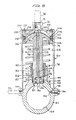
- FIG. 60 An external housing is shown at numeral 60 including a spherical section 62 having heavy walls for resisting very high liquid pressures.
- a very high pressure spherical chamber 64 is enclosed within the walls of section 62.
- Housing 60 also encloses a cylindrical chamber 66 which is closed at one end by means of an end cap member 68 including a boss 70 containing an inlet passage 72 which is adapted to be threadedly engaged with a conduit 24 (see Figure 1) connected to the high pressure source.
- Movable within the cylinder 66 is a piston 74 to which is attached a rod 76.
- a spring 78 urges piston 74 toward the end cap member 68.
- Part of the wall of section 62 which is directed toward the inside housing 60 includes a cylindrical opening 80 for receiving and supporting the end of rod 76.
- a portion of the cylindrical passageway 80 is of expanded diameter as shown at numeral 82 and this opening combined with a member 84, which surrounds and partially supports the rod 76, together define an annular groove which receives a seal consisting of a rubber O-ring 85 covered by an annular seal 86 of polytetrafluoroethylene material and a plurality of metal and plastic backup rings 88.
- An.additional expanded diameter collar 90 constituting an extension of section 62 which supports the rod 76 is threadedly engaged with a member 92 which, as it is turned into the inside of collar 90, compresses the seal members such that they provide a proper seal between section 62 and the end of the rod 76. This must be an unusually good seal because of the extremely high pressures within chamber 64.
- a small passageway 94 which is normally closed by means of a bleed valve member 96 threadedly engaged with housing 60 and which communicates with another small passageway 98 leading to the interior of cylindrical chamber 66.
- Bleed valve member 96 provides a means of permitting the contents of chamber 64 to be exhausted through passageways 94 and 98, the interior of cylindrical chamber 66, and out of a port 100 which leads to the return line 22 (see Figure 1).
- piston 74 includes a stepped groove arrangement 102 at its periphery which contains a seal including an 0-ring member 104 and a plurality of metal and plastic backup rings 106.
- a small sealing ring 112 Radially inwardly from the O-ring 104 is a small sealing ring 112 which senses system pressure tending to drive the 0-ring radially outward.
- This ring 112 is placed adjacent another small ring 116, and each of these rings is adjacent a small annulus 114 which communicates pressure forcing ring 112 outwardly.
- Ring 116 serves to prevent ring 112 from blocking ports (not shown) communicating the annulus 114 with the sealing ring 104.
- An essentially identical sealing arrangement is used in both the end cap 68 and the piston 74.
- the end cap 68 is secured in the housing 60 by means of a shear ring 118 which is secured against a shoulder in the end cap 68 and within a groove in the housing 60 to prevent internal pressure acting on the inside of the end cap 68 from forcing this end cap out of the housing 60.
- a small plate 120 is secured to the end cap 68 by means of a series of bolts 122 which feed through some heavy washers 124 and which are threadedly engaged with the end cap 68. Since end plate 120 extendes over the ends of the housing 60, the arrangement described will prevent end cap 68 from moving inwardly as a result of any unusual low pressures in the interior of cylindrical chamber 66 or from external forces.
- a small diameter passageway 126 is drilled through the central axis of piston 74 and rod 76, and this passageway contains a shaft 128 fastened to a check valve member 130.
- this passage is expanded to include a valve seat area 132 which is circular and formed at right angles to the axis of the shaft 128.
- the check valve member 130 has a flat circular face opposing seat 132 and includes a plurality of annular rings 134 which make contact against seat 132.
- a light spring 136 tends to urge check valve member 130 against the seat 132.
- shaft 128 is secured in annular support members 138 and 140 which freely permit the passage of liquid therethrough.
- the liquid spring accumulator of Figure 2 although slightly different in configuration from that described above, operates in almost exactly the same manner. Hydraulic oil supplied under initial pressure to inlet port 72 will pass through a plurality of passages 142 to the adjacent surface of piston 74 and will also flow through the passageway 126 and past check valve member 130 into chamber 64. Check valve 130 is held open because the shaft 128 is in direct contact with the end cap member 68. Further increases in fluid pressure applied to the upper end of piston 74 will cause the piston to move downwardly against the force of spring 78, carrying the shaft 128 away from its contact with end cap 68 and permitting the check valve member 130 to close against seat 132.
- piston 74 and rod 76 will continue to move downwardly, forcing rod 76 into chamber 64 where a comparatively small displacement of the rod will result in rapid increases in the fluid pressure.
- This pressure will increase until a stability is reached wherein the system pressure operating on the area of piston 74 equals the pressure in housing 64 acting on the smaller area of rod 76.
- the resulting liquid pressure in housing 64 will approach a value 10 times that of the system pressure. This pressure is then available in the system to supply energy during peaks of demand as required or to absorb pressure surges.
Landscapes
- Engineering & Computer Science (AREA)
- Physics & Mathematics (AREA)
- Fluid Mechanics (AREA)
- Mechanical Engineering (AREA)
- General Engineering & Computer Science (AREA)
- Supply Devices, Intensifiers, Converters, And Telemotors (AREA)
Claims (5)
Applications Claiming Priority (2)
| Application Number | Priority Date | Filing Date | Title |
|---|---|---|---|
| US06/357,968 US4450870A (en) | 1982-03-15 | 1982-03-15 | Liquid spring accumulator with self-charging means |
| US357968 | 1982-03-15 |
Publications (3)
| Publication Number | Publication Date |
|---|---|
| EP0089286A2 EP0089286A2 (de) | 1983-09-21 |
| EP0089286A3 EP0089286A3 (en) | 1984-08-29 |
| EP0089286B1 true EP0089286B1 (de) | 1987-05-06 |
Family
ID=23407767
Family Applications (1)
| Application Number | Title | Priority Date | Filing Date |
|---|---|---|---|
| EP83400509A Expired EP0089286B1 (de) | 1982-03-15 | 1983-03-11 | Flüssigkeitsfederspeicher mit Selbstaufladungsvorrichtung |
Country Status (4)
| Country | Link |
|---|---|
| US (1) | US4450870A (de) |
| EP (1) | EP0089286B1 (de) |
| JP (1) | JPS58166101A (de) |
| DE (1) | DE3371397D1 (de) |
Families Citing this family (8)
| Publication number | Priority date | Publication date | Assignee | Title |
|---|---|---|---|---|
| CA1232824A (en) * | 1983-11-30 | 1988-02-16 | Shoso Ishimori | Running apparatus for an agricultural vehicle |
| DE10350941A1 (de) * | 2003-10-31 | 2005-06-02 | Hydac Technology Gmbh | Vorrichtung zum Dämpfen von Druckstößen |
| US9212670B2 (en) * | 2012-02-08 | 2015-12-15 | Gm Global Technology Operations, Llc | Composite accumulator |
| US9739292B1 (en) | 2014-03-21 | 2017-08-22 | Kocsis Technologies, Inc. | Hydraulic accumulator having a closing arrangement |
| US9992910B2 (en) * | 2015-06-11 | 2018-06-05 | Cooler Master Co., Ltd. | Liquid supply mechanism and liquid cooling system |
| US10954966B2 (en) * | 2017-10-25 | 2021-03-23 | Raytheon Company | Bootstrap accumulator containing integrated bypass valve |
| CN113217482B (zh) * | 2021-04-09 | 2022-03-11 | 燕山大学 | 一种内置单向阀的活塞式蓄能器 |
| US20240263649A1 (en) * | 2021-05-13 | 2024-08-08 | Advanced Energy Storage, Llc | Accumulator with reinforcing structure |
Family Cites Families (9)
| Publication number | Priority date | Publication date | Assignee | Title |
|---|---|---|---|---|
| US2546055A (en) * | 1944-09-02 | 1951-03-20 | Charles U Ballard | Compensator |
| US2780504A (en) * | 1954-04-21 | 1957-02-05 | Parker Appliance Co | Accumulator piston |
| US2943642A (en) * | 1958-07-07 | 1960-07-05 | Cleveland Pneumatic Ind Inc | Liquid spring accumulator |
| US3348579A (en) * | 1965-03-26 | 1967-10-24 | Int Harvester Co | Self-adjusting pulsating fluid pressure damping accumulator |
| US3473328A (en) * | 1967-11-01 | 1969-10-21 | Jergens Tool Specialty Co | Pressure multiplying booster |
| FR2133497B1 (de) * | 1971-04-15 | 1974-03-08 | Claret Lucien | |
| FR2154274B1 (de) * | 1971-08-19 | 1977-01-21 | Westinghouse Freins & Signaux | |
| US3907001A (en) * | 1973-02-12 | 1975-09-23 | Pneumo Dynamics Corp | Combination accumulator reservoir |
| GB2100347A (en) * | 1981-06-15 | 1982-12-22 | Phillips Bruce Howard | Hydraulic booster assembly |
-
1982
- 1982-03-15 US US06/357,968 patent/US4450870A/en not_active Expired - Lifetime
-
1983
- 1983-03-11 EP EP83400509A patent/EP0089286B1/de not_active Expired
- 1983-03-11 DE DE8383400509T patent/DE3371397D1/de not_active Expired
- 1983-03-15 JP JP58041642A patent/JPS58166101A/ja active Pending
Also Published As
| Publication number | Publication date |
|---|---|
| DE3371397D1 (en) | 1987-06-11 |
| EP0089286A3 (en) | 1984-08-29 |
| EP0089286A2 (de) | 1983-09-21 |
| US4450870A (en) | 1984-05-29 |
| JPS58166101A (ja) | 1983-10-01 |
Similar Documents
| Publication | Publication Date | Title |
|---|---|---|
| US3015345A (en) | Combination reservoir-accumulator arrangement for hydraulic system | |
| US4777800A (en) | Static head charged hydraulic accumulator | |
| US3886848A (en) | Pressure operated directional control valve | |
| JPH02102901A (ja) | 空気油圧増圧式の圧力変換器の圧油充填法及びその方法を実施するための装置 | |
| US4368008A (en) | Reciprocating controls of a gas compressor using free floating hydraulically driven piston | |
| US4527580A (en) | Volume control device | |
| US5377488A (en) | Hydro-pneumatic pressure transformer | |
| EP0089286B1 (de) | Flüssigkeitsfederspeicher mit Selbstaufladungsvorrichtung | |
| JPS60208613A (ja) | 油圧制御装置 | |
| EP0057996A1 (de) | Durch Druckmittel getriebene Kolbenvorrichtung | |
| US20080078455A1 (en) | Compact Manifolded Fail Safe Hydraulic Control System | |
| US2731038A (en) | Hydraulic accumulator | |
| EP1226333B1 (de) | Unterwassersystem mit vorrichtung zur kontrolle eines hydraulischen betätigungswerkzeuges und mit einem solchen werkzeug | |
| US3198213A (en) | Unit area ratio accumulator with fail-safe means | |
| EP0414674B1 (de) | Hauptzylinder mit schnellfüllventil | |
| US2604230A (en) | Liquid supply tank | |
| US3962956A (en) | Hydropneumatic valve actuator | |
| US4291718A (en) | Pressure valve | |
| US3718158A (en) | Accumulator control system | |
| US3064687A (en) | Combined accumulator-relief valve | |
| US5927178A (en) | Press driven tool actuator module | |
| GB2092717A (en) | Hydraulic control valve assembly | |
| US12270397B2 (en) | Pump configuration including a purge valve for removing airlocks | |
| GB2096223A (en) | Improvements in hydraulic control apparatus for controlling the operation of mine roof support props | |
| US3656708A (en) | Dump valve |
Legal Events
| Date | Code | Title | Description |
|---|---|---|---|
| PUAI | Public reference made under article 153(3) epc to a published international application that has entered the european phase |
Free format text: ORIGINAL CODE: 0009012 |
|
| 17P | Request for examination filed |
Effective date: 19830322 |
|
| AK | Designated contracting states |
Designated state(s): DE FR GB |
|
| PUAL | Search report despatched |
Free format text: ORIGINAL CODE: 0009013 |
|
| AK | Designated contracting states |
Designated state(s): DE FR GB |
|
| 17Q | First examination report despatched |
Effective date: 19860127 |
|
| RAP1 | Party data changed (applicant data changed or rights of an application transferred) |
Owner name: ALLIED CORPORATION |
|
| GRAA | (expected) grant |
Free format text: ORIGINAL CODE: 0009210 |
|
| AK | Designated contracting states |
Kind code of ref document: B1 Designated state(s): DE FR GB |
|
| REF | Corresponds to: |
Ref document number: 3371397 Country of ref document: DE Date of ref document: 19870611 |
|
| ET | Fr: translation filed | ||
| PLBE | No opposition filed within time limit |
Free format text: ORIGINAL CODE: 0009261 |
|
| STAA | Information on the status of an ep patent application or granted ep patent |
Free format text: STATUS: NO OPPOSITION FILED WITHIN TIME LIMIT |
|
| 26N | No opposition filed | ||
| PGFP | Annual fee paid to national office [announced via postgrant information from national office to epo] |
Ref country code: GB Payment date: 19910304 Year of fee payment: 9 |
|
| PGFP | Annual fee paid to national office [announced via postgrant information from national office to epo] |
Ref country code: FR Payment date: 19910320 Year of fee payment: 9 |
|
| PGFP | Annual fee paid to national office [announced via postgrant information from national office to epo] |
Ref country code: DE Payment date: 19910402 Year of fee payment: 9 |
|
| PG25 | Lapsed in a contracting state [announced via postgrant information from national office to epo] |
Ref country code: GB Effective date: 19920311 |
|
| GBPC | Gb: european patent ceased through non-payment of renewal fee | ||
| PG25 | Lapsed in a contracting state [announced via postgrant information from national office to epo] |
Ref country code: FR Effective date: 19921130 |
|
| PG25 | Lapsed in a contracting state [announced via postgrant information from national office to epo] |
Ref country code: DE Effective date: 19921201 |
|
| REG | Reference to a national code |
Ref country code: FR Ref legal event code: ST |