EP0089093B1 - Sun heating equipment - Google Patents
Sun heating equipment Download PDFInfo
- Publication number
- EP0089093B1 EP0089093B1 EP83200355A EP83200355A EP0089093B1 EP 0089093 B1 EP0089093 B1 EP 0089093B1 EP 83200355 A EP83200355 A EP 83200355A EP 83200355 A EP83200355 A EP 83200355A EP 0089093 B1 EP0089093 B1 EP 0089093B1
- Authority
- EP
- European Patent Office
- Prior art keywords
- line
- absorbing plate
- vacuum pump
- heat
- fluid
- Prior art date
- Legal status (The legal status is an assumption and is not a legal conclusion. Google has not performed a legal analysis and makes no representation as to the accuracy of the status listed.)
- Expired
Links
Images



Classifications
-
- F—MECHANICAL ENGINEERING; LIGHTING; HEATING; WEAPONS; BLASTING
- F24—HEATING; RANGES; VENTILATING
- F24D—DOMESTIC- OR SPACE-HEATING SYSTEMS, e.g. CENTRAL HEATING SYSTEMS; DOMESTIC HOT-WATER SUPPLY SYSTEMS; ELEMENTS OR COMPONENTS THEREFOR
- F24D11/00—Central heating systems using heat accumulated in storage masses
- F24D11/002—Central heating systems using heat accumulated in storage masses water heating system
- F24D11/003—Central heating systems using heat accumulated in storage masses water heating system combined with solar energy
-
- F—MECHANICAL ENGINEERING; LIGHTING; HEATING; WEAPONS; BLASTING
- F24—HEATING; RANGES; VENTILATING
- F24S—SOLAR HEAT COLLECTORS; SOLAR HEAT SYSTEMS
- F24S10/00—Solar heat collectors using working fluids
- F24S10/60—Solar heat collectors using working fluids the working fluids trickling freely over absorbing elements
-
- F—MECHANICAL ENGINEERING; LIGHTING; HEATING; WEAPONS; BLASTING
- F24—HEATING; RANGES; VENTILATING
- F24S—SOLAR HEAT COLLECTORS; SOLAR HEAT SYSTEMS
- F24S10/00—Solar heat collectors using working fluids
- F24S10/90—Solar heat collectors using working fluids using internal thermosiphonic circulation
- F24S10/95—Solar heat collectors using working fluids using internal thermosiphonic circulation having evaporator sections and condenser sections, e.g. heat pipes
-
- F—MECHANICAL ENGINEERING; LIGHTING; HEATING; WEAPONS; BLASTING
- F24—HEATING; RANGES; VENTILATING
- F24S—SOLAR HEAT COLLECTORS; SOLAR HEAT SYSTEMS
- F24S40/00—Safety or protection arrangements of solar heat collectors; Preventing malfunction of solar heat collectors
- F24S40/40—Preventing corrosion; Protecting against dirt or contamination
- F24S40/48—Deaerating or degassing the working fluid
-
- F—MECHANICAL ENGINEERING; LIGHTING; HEATING; WEAPONS; BLASTING
- F24—HEATING; RANGES; VENTILATING
- F24S—SOLAR HEAT COLLECTORS; SOLAR HEAT SYSTEMS
- F24S80/00—Details, accessories or component parts of solar heat collectors not provided for in groups F24S10/00-F24S70/00
- F24S80/30—Arrangements for connecting the fluid circuits of solar collectors with each other or with other components, e.g. pipe connections; Fluid distributing means, e.g. headers
-
- Y—GENERAL TAGGING OF NEW TECHNOLOGICAL DEVELOPMENTS; GENERAL TAGGING OF CROSS-SECTIONAL TECHNOLOGIES SPANNING OVER SEVERAL SECTIONS OF THE IPC; TECHNICAL SUBJECTS COVERED BY FORMER USPC CROSS-REFERENCE ART COLLECTIONS [XRACs] AND DIGESTS
- Y02—TECHNOLOGIES OR APPLICATIONS FOR MITIGATION OR ADAPTATION AGAINST CLIMATE CHANGE
- Y02B—CLIMATE CHANGE MITIGATION TECHNOLOGIES RELATED TO BUILDINGS, e.g. HOUSING, HOUSE APPLIANCES OR RELATED END-USER APPLICATIONS
- Y02B10/00—Integration of renewable energy sources in buildings
- Y02B10/20—Solar thermal
-
- Y—GENERAL TAGGING OF NEW TECHNOLOGICAL DEVELOPMENTS; GENERAL TAGGING OF CROSS-SECTIONAL TECHNOLOGIES SPANNING OVER SEVERAL SECTIONS OF THE IPC; TECHNICAL SUBJECTS COVERED BY FORMER USPC CROSS-REFERENCE ART COLLECTIONS [XRACs] AND DIGESTS
- Y02—TECHNOLOGIES OR APPLICATIONS FOR MITIGATION OR ADAPTATION AGAINST CLIMATE CHANGE
- Y02E—REDUCTION OF GREENHOUSE GAS [GHG] EMISSIONS, RELATED TO ENERGY GENERATION, TRANSMISSION OR DISTRIBUTION
- Y02E10/00—Energy generation through renewable energy sources
- Y02E10/40—Solar thermal energy, e.g. solar towers
- Y02E10/44—Heat exchange systems
-
- Y—GENERAL TAGGING OF NEW TECHNOLOGICAL DEVELOPMENTS; GENERAL TAGGING OF CROSS-SECTIONAL TECHNOLOGIES SPANNING OVER SEVERAL SECTIONS OF THE IPC; TECHNICAL SUBJECTS COVERED BY FORMER USPC CROSS-REFERENCE ART COLLECTIONS [XRACs] AND DIGESTS
- Y10—TECHNICAL SUBJECTS COVERED BY FORMER USPC
- Y10S—TECHNICAL SUBJECTS COVERED BY FORMER USPC CROSS-REFERENCE ART COLLECTIONS [XRACs] AND DIGESTS
- Y10S126/00—Stoves and furnaces
- Y10S126/906—Connecting plural solar collectors as a unit
Definitions
- This invention relates to a sun heating equipment comprising
- water can be used as heat-transfer fluid without problems of freezing in the collector. Also the inertia of the equipment is very low.
- vacuum pump is directly mounted in the line, fluid is not fed to the collector by means of this vacuum pump, but by means of a separate feeding pump mounted in the line.
- the equipment is of a more simple structure. It has no separator but also no vacuum pump in the line. It also has neither a venting tank nor a separated flow control device, the flow rate being determined by the feeding pump itself which is controlled depending on temperatures in the collector and in the storage tank.
- the invention has for object to provide a sun heating equipment of the above defined type which has a quite simple structure, allows a good heat transfer between the collector and the heat-transfer fluid and which gives a good yield.
- the vacuum pump itself combined with the venting cylinder creates the required low pressure in the plate and in the line in order to have good evaporation conditions in the collector and good condensation conditions of the vapour which has been formed in the collector.
- the efficiency of the equipment according to USA4 124 020 is thus rather low because the space of the collector is only bounded on one single side by a full absorbing plate and consequently the collector can only receive solar energy from one side and because moreover the heat transported from the collector to the means removing heat from the line, is only comprised of the heat which brought the liquid at a higher temperature and does not comprise heat of evaporation.
- the equipment does not comprise means enhancing the evaporation in the collector by lowering the pressure and consequently permitting recovery of the heat of evaporation by condensation.
- the flow control device lets through a constant flow rate which is substantially equal to that flow rate which can be vaporized in the absorbing plate with a maximum sun radiation on said absorbing plate.
- the flow control device lets through a flow rate which is substantially equal at every moment, to that flow rate which can be vaporized in the absorbing plate with the sun radiation present on that moment which falls on said absorbing plate.
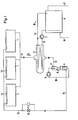
- the sun heating equipment as shown in figure 1 comprises a number of sun collectors 1, a line 12 which connects the outlet from said sun collectors 1 to the inletthereof, and means to remove heat from said line 12.
- the vacuum pump 3 Downstream of said collectors 1 is mounted a vacuum pump 3 and inside collectors 1 is mounted a distributing device 14 which feeds the water with a pressure drop and a small flow rate to the inner side of said collectors 1. There appears thereby an underpressure inside collectors 1. Consequently that water which is fed to the collectors 1 can be vaporized at a lower temperature and is mainly present as vapour inside said collectors.
- the vacuum pump 3 is a pump type which can pump both gaseous and liquid fluid.
- the means for removing heat from line 12 are formed by a heat exchanger 2 designed as a condenser.
- the primary part thereof is mounted upstream of vacuum pump 3, between said pump and collectors 1.
- the secondary part thereof is part of a hot water line 15 which runs in closed circuit and wherein are mounted a circulating pump 7 and upstream thereof, between said pump 7 and heat exchanger 2, a storage tank 8 for hot water.
- the water flow direction in hot water line 15 is shown with an arrow 16.
- Those portions of line 15 lying upstream and downstream of storage tank 8 connect respectively at the top and bottom to storage tank 8.
- a discharge line 17 and a supply line 18 also connect respectively at the top and bottom, to the water storage tank 8.
- the water vapour which has been formed inside collectors 1, is condensed.
- heat exchanger 2 use may be made of a steam condenser available in the trade, but said heat exchanger 2 may usefully be formed by a tube which is arranged inside a closed vessel. Said vessel forms the primary part and the tube the secondary part of the heat exchanger.
- venting cylinder 4 Downstream of the vacuum pump 3, in line 12 is mounted a venting cylinder 4 which thus communicates with the pressure side of vacuum pump 3. Said venting cylinder is provided with an automatic-working venting valve with a non-return valve 6. Non-condensable gases may be removed from the equipment by means of said venting cylinder.
- the vacuum pump 3 is a water-jet pump.
- the vacuum chamber of said water-jet pump is connected to the upstream portion of line 12, while the jet pipe thereof is connected to a return line 19 which is connected to venting cylinder 4.
- the water-jet pump 3 is driven by means of a pump 5 mounted in said return line 19, which forces water from said venting cylinder 4 through the jet pipe of said water-jet pump 3.
- the collectors 1 are to the exception of the distributing device 14, of a type which has been described in detail in BE-A-892 527, which is incorporated hereby as reference. They comprise a heat-absorbing wall in the form of an absorbing plate 22 which is mounted inside a housing not shown in the figures, with one or a plurality of translucid walls which let sun energy through, but let as little as possible heat escape.
- Said absorbing plate 22 is designed as a panel of a panel radiator for central heating and it is thus comprised of two rectangular metal panels 23 which are welded together with the edges 24 thereof, and which are provided with depressions 25 running in the cross-wise direction thereof, in such a way that between both panels 23 are formed channels 26 running in the cross-wise direction, which open on the one hand on a feed space 27 and on the other hand on a discharge space 28.
- the cross-wise direction lies vertically.
- To said discharge space 28 connects a discharge part 29 with which said space 28 connects to line 12, while inside said feed space 27 is mounted the distributing device 14, which connects with one end through a feed line 30, to the upstream portion of line 12.
- the feed line 30, the distributing device 14, the feed space 27, the channels 26, the discharge space 28, and the discharge part 29 are thus cut-in, in sequence along the flow direction: the feed line 30, the distributing device 14, the feed space 27, the channels 26, the discharge space 28, and the discharge part 29.
- the panels 23 of said absorbing plate 22 are coated on the outer side with a heat-absorbing material. On the inner side, said panels are easily moistenable and not water-repellent. Said panels 23 are for example steel panels which are slightly rusted on the moistenable inner side.
- the distributing device 14 is comprised of a thin-walled polytetrafluorethylene (PTFE) hose 31 which extends inside said feed space 27 along the lengthwise direction of absorbing plate 22. Said hose 31 is provided at regular intervals with slits 32.
- PTFE polytetrafluorethylene
- Said hose 31 is widened at the one end thereof. Said hose is clamped with said widened end 33 on the stainless steel feed line 30. The opposite end of hose 31 is closed by a plug not shown in the figures.
- the desired flow rate is obtained and a regular moistening of the inner side of absorbing plate 22 may be obtained.
- an overpressure of 2 to 3 bar the slits 32 so open as to obtain a large flow rate and a flushing of said hose 31 occurs, and possible obstructions of said slits 32 after extended operation may be eliminated.
- the pressure drop inside distributing device 14 should be high enough relative to the line losses, in such a way that that portion lying upstream of collectors 1, of line 12 can be subjected to a high enough pressure, but the flow rate in said collectors 1 still remains limited.
- the adjusting of the flow rate inside the collectors 1 may be determined by said distributing device 14.
- the flow rate may however also be adjusted by an additional flow-control device 10 which is mounted upstream of collectors 1 in said line 12.
- Said flow-control device 10 may either adjust a constant flow rate, or adjust a flow rate which varies according to the sun radiation.
- said device 10 is comprised of a cock which is cut-in in said line 12 and the opening of which is automatically regulated according to the pressure differential upstream and downstream of said cock, and as the case requires also according to the sun radiation.
- the flow rate is adjusted in any case in such a way that the moistenable inner walls of panels 23 of said absorbing plates 22 of collectors 1 are moistened at the top at least without however the channels 26 which are formed between said panels 23 being completely filled with water at any height whatsoever.
- the water forms but a film over the inner wall, which vaporizes as it flows down.
- the flow control device 10 is then so adjusted as to let a constant flow rate flow to the collectors 1, which is equal to or hardly higher than the flow rate which can be vaporized with the maximum received sun radiation in said collectors 1. In this way there is always obtained a complete moistening of the absorbing plates 22, which insures an optimum heat discharge.
- the flow rate is usually about two liters per hour per m 2 collector surface area. With a lower sun radiation, an excess water is fed to said absorbing plates 22. Such excess water flows due to gravity, through collectors 1.
- the flow control device 10 When it is desired to obtain a flow rate which is dependent on the sun radiation, the flow control device 10 lets through a water flow rate which corresponds at every moment to that flow rate which can be vaporized inside said collectors 1 with that sun radiation present on that moment. All of the water which flows into said collectors 1 is also vaporized therein.
- the heat inertia of said collectors 1 Due to little or no liquid being present inside the collectors, and such liquid flowing as a thin film over said absorbing plate 22, the heat inertia of said collectors 1 is limited to the heat inertia of said absorbing plates 22 and such inertia is thus very low. There is thus no freezing or overheating problem, and the heat-transfer coefficient is quite high due to the water vaporizing inside said collectors 1.
- the embodiment of the equipment as shown in figure 4 differs from the above-described equipment but in the vacuum pump 3 being no water-jet pump but rather a liquid-ring vacuum pump.
- Pumps of liquid-ring type are known as such. They mainly comprise a cylinder-shaped pump housing wherein a radial blade wheel is mounted eccentrically. The sealing between said blade wheel and the pump housing casing is obtained with liquid, generally water, which is forced against the casing by the centrifugal force as the blade wheel rotates. The space between two blades and inside said liquid ring increases and decreases in sequence at each revolution of the blade wheel, in such a way that a suction and respectively a pressurizing occurs.
- the pump inlet and outlet and arranged in the pump housing ends, opposite part of that space inside the liquid ring where the suction, respectively the pressurizing occurs.
- Such pumps can suck gases as well as liquids, and can generate high overpressures on the pressure side.
- Said liquid-ring vacuum pump 3 also pumps the condensate from the heat exchanger 2 to the venting cylinder 4 and thus insures an underpressure inside collectors 1.
- a return line 20 wherein a valve 21 is mounted, shunts the vacuum pump 3 and connects on the one hand to venting cylinder 4, and on the other hand to that portion lying between pump 3 and heat exchanger 2, of line 12.
- Said return line 20 maintains the flowing through the liquid-ring pump with a flow rate which is regulated by valve 21. This is necessary when the flow rate through line 12 is too small to insure normal operation of pump 3.
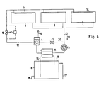
- the embodiment of the sun heating equipment as shown in figure 5 differs from the embodiment as shown in figure 4 in the condenser-designed heat exchanger 2 being replaced by a usual water/ water heat exchanger 11 which moreover does not lie upstream of the liquid-ring vacuum pump 3, but rather between said pump 3 and the venting cylinder 4, in line 12.
- the primary part of heat exchanger 11 lies in line 12, while the secondary part thereof is mounted in hot water line 15.
- the operation of the sun heating equipment as shown in figure 5 is similar to the operation of the sun heating equipment as shown in figure 4, to that difference that the condensing of the water vapour does not occur inside the heat exchanger, but rather inside the vacuum pump 3.
- the vacuum pump 3 is also a liquid-ring vacuum pump which fulfils the function of condenser.
- the equipment does not comprise a discrete venting cylinder in line 12, but the function of said cylinder is fulfilled by tank 8, which tank also forms the means for removing heat from line 12.
- Said storage tank 8 is then also directly mounted in line 12, downstream of the liquid-ring vacuum pump 3. That portion lying upstream of storage tank 8 of said line 12 opens on the top side of said tank.
- To the top of said storage tank 8 connects an automatic venting device 6.
- the return line 20 connects directly to the bottom of storage.tank 8, instead of to the venting cylinder.
- Electro-magnetic stop valves 9 are mounted upstream of tank 8, respectively in line 12 and return line 20. Said stop valves 9 are opened but after pump 3 has started working.
- the collectors 1 are identical to the collectors in the previous embodiments, and upstream of said collectors, a flow control device 10 is also mounted in line 12. The flow rate regulating cock of said device 10 is, as well as the stop valves 9, opened but after the pump 3 has started working. Heat is removed from line 12 due to hot water being discharged from storage tank 8 and thus from line 12 through discharge line 17, and replaced by cold water which is fed to tank 8 through feed line 18. The hot water from line 12 itself is being used and the heat-transfer water is not discrete from the water being used.
- the channels 26 inside the absorbing plates 22 are nowhere completely filled with water, in such a way that freezing of said water cannot cause damage to the absorbing plates 22.
Landscapes
- Engineering & Computer Science (AREA)
- Life Sciences & Earth Sciences (AREA)
- Sustainable Development (AREA)
- Sustainable Energy (AREA)
- Thermal Sciences (AREA)
- Chemical & Material Sciences (AREA)
- Combustion & Propulsion (AREA)
- Mechanical Engineering (AREA)
- General Engineering & Computer Science (AREA)
- Physics & Mathematics (AREA)
- Sorption Type Refrigeration Machines (AREA)
- Processing And Handling Of Plastics And Other Materials For Molding In General (AREA)
- Window Of Vehicle (AREA)
- Basic Packing Technique (AREA)
- Steam Or Hot-Water Central Heating Systems (AREA)
- Heat-Pump Type And Storage Water Heaters (AREA)
- Central Heating Systems (AREA)
- Photovoltaic Devices (AREA)
- Instantaneous Water Boilers, Portable Hot-Water Supply Apparatuses, And Control Of Portable Hot-Water Supply Apparatuses (AREA)
- Road Signs Or Road Markings (AREA)
- Buildings Adapted To Withstand Abnormal External Influences (AREA)
Abstract
Description
- This invention relates to a sun heating equipment comprising
- -at least one sun collector, which comprises at least one upwardly extending hollow tightly- closed absorbing plate and presents an inlet for heat-transfer fluid at the top of the absorbing plate and an outlet for said fluid at the bottom of the absorbing plate,
- - a line for said heat-transfer fluid which con- nectsthe outlet of said collectorto the inletthereof,
- - a vacuum pump which is directly mounted in said line and which is of such a type which can pump as well gaseous as liquid fluid,
- -a flow control device which is mounted upstream of said absorbing plate and lets through a flow rate of fluid in liquid form which is substantially equal to thatflow rate which can be vaporized in the absorbing plate with a determined sun radiation on said absorbing plate so that the fluid does not fill completely at any height whatsoever said absorbing plate and is vaporized at least for the most part before reaching the bottom of said absorbing plate, and
- - means to permit condensation of the vaporized heat-transfer fluid and to remove heat from the fluid inside said line.
- As the collector is not filled with fluid in liquid form, water can be used as heat-transfer fluid without problems of freezing in the collector. Also the inertia of the equipment is very low.
- An equipment of this kind is known from figure 2 of DE-A-26 01 673. In this known embodiment no venting means are provided in the line so that good evaporation conditions in the collector and a good condensation of the vapour formed in the collector are not always possible.
- Moreover, although the vacuum pump is directly mounted in the line, fluid is not fed to the collector by means of this vacuum pump, but by means of a separate feeding pump mounted in the line.
- Between the vacuum pump and the feeding pump not only a storage tank wherein the vapour condenses and which forms the means to remove heat but also a liquid-vapour separator is mounted.
- The construction of the equipment is therefore rather complicated and the yield rather low.
- In the embodiment according to figure 1 of DE-A-26 01 673 the equipment is of a more simple structure. It has no separator but also no vacuum pump in the line. It also has neither a venting tank nor a separated flow control device, the flow rate being determined by the feeding pump itself which is controlled depending on temperatures in the collector and in the storage tank.
- In none of these embodiments the structure of the collector is described.
- The invention has for object to provide a sun heating equipment of the above defined type which has a quite simple structure, allows a good heat transfer between the collector and the heat-transfer fluid and which gives a good yield.
- For this purpose
- -the absorbing plate comprises two panels which are secured with the edges thereof to one another and which have depressions extending in a first direction over part of the absorbing plate width and thusforming flowchannels extending in this first direction, said flow channels connecting said inlet with said outlet inside said absorbing plate, the inner walls of said absorbing plate being moistenable at least in the location of the flow channels,
- - the equipment comprises
- -- a distributing device which extends in a direction perpendicular to the above-mentioned first direction ofthe flow channels and which feeds the fluid in liquid form with a limited flow rate to said flow channels, so as to have the moistenable walls regularly irrigated at least at the top with a thin film of liquid fluid, and
- - - a venting tank between said vacuum pump and said inlet and
- - the vacuum pump is connected with its outlet to the inlet of the collector so as to function as feeding pump feeding fluid to the collector.
- The vacuum pump itself combined with the venting cylinder creates the required low pressure in the plate and in the line in order to have good evaporation conditions in the collector and good condensation conditions of the vapour which has been formed in the collector.
- The use of a distributing device distributing the liquid in the form of a film to an absorbing plate is known as such from US-A-4 124 020. The liquid is however distributed on the underside of a single plate and not on both inner sides of flow channels.
- The efficiency of the equipment according to USA4 124 020 is thus rather low because the space of the collector is only bounded on one single side by a full absorbing plate and consequently the collector can only receive solar energy from one side and because moreover the heat transported from the collector to the means removing heat from the line, is only comprised of the heat which brought the liquid at a higher temperature and does not comprise heat of evaporation. The equipment does not comprise means enhancing the evaporation in the collector by lowering the pressure and consequently permitting recovery of the heat of evaporation by condensation.
- In a particular embodiment of the invention, the flow control device lets through a constant flow rate which is substantially equal to that flow rate which can be vaporized in the absorbing plate with a maximum sun radiation on said absorbing plate.
- In another particular embodiment of the invention, the flow control device lets through a flow rate which is substantially equal at every moment, to that flow rate which can be vaporized in the absorbing plate with the sun radiation present on that moment which falls on said absorbing plate.
- Other details and advantages of the invention will stand out from the following description of four embodiments of a sun heating equipment according to the invention; this description is only given by way of example and does not limit the invention; the reference numerals pertain to the accompanying drawings.
- Figure 1 is a diagrammatic showing of a sun heating equipment according to the invention.
- Figure 2 is a front view with parts cut-away of a portion of an absorbing plate of a sun collector of the equipment according to figure 1 but drawn on a larger scale.
- Figure 3 is a cross-section along line III-III in figure 2, but drawn on a still larger scale.
- Figure 4 is a diagrammatic showing similar to figure 1 of a sun heating equipment according to the invention, but pertaining to another embodiment of such equipment.
- Figure 5 is a diagrammatic showing similar to figures 1 and 4, of a sun heating equipment according to the invention but pertaining to a third embodiment of such an equipment.
- Figure 6 is a diagrammatic showing similar to figures 1, 4 and 5, of a sun heating equipment according to the invention, but pertaining to a fourth embodiment of such an equipment. In the various figures, the same reference numerals pertain to similar elements.
- The sun heating equipment as shown in figure 1, as other known equipments, comprises a number of
sun collectors 1, aline 12 which connects the outlet from saidsun collectors 1 to the inletthereof, and means to remove heat from saidline 12. - In figure 1 have been shown but three
collectors 1, but it is clear that the equipment may have any number ofcollectors 1. In that case where the equipment comprises more than onecollector 1, said collectors are connected in parallel to saidline 12, whereby thus all of the inlets thereof communicate with all of the outlets therefrom. The flow direction of the water throughline 12 is shown with anarrow 13 in figure 1. - Downstream of said
collectors 1 is mounted avacuum pump 3 and insidecollectors 1 is mounted a distributingdevice 14 which feeds the water with a pressure drop and a small flow rate to the inner side of saidcollectors 1. There appears thereby an underpressure insidecollectors 1. Consequently that water which is fed to thecollectors 1 can be vaporized at a lower temperature and is mainly present as vapour inside said collectors. Thevacuum pump 3 is a pump type which can pump both gaseous and liquid fluid. - The means for removing heat from
line 12 are formed by aheat exchanger 2 designed as a condenser. The primary part thereof is mounted upstream ofvacuum pump 3, between said pump andcollectors 1. The secondary part thereof is part of ahot water line 15 which runs in closed circuit and wherein are mounted a circulatingpump 7 and upstream thereof, between saidpump 7 andheat exchanger 2, astorage tank 8 for hot water. The water flow direction inhot water line 15 is shown with anarrow 16. Those portions ofline 15 lying upstream and downstream ofstorage tank 8 connect respectively at the top and bottom tostorage tank 8. Adischarge line 17 and asupply line 18 also connect respectively at the top and bottom, to thewater storage tank 8. Inside the primary part ofheat exchanger 2, the water vapour which has been formed insidecollectors 1, is condensed. Asheat exchanger 2, use may be made of a steam condenser available in the trade, but saidheat exchanger 2 may usefully be formed by a tube which is arranged inside a closed vessel. Said vessel forms the primary part and the tube the secondary part of the heat exchanger. - Downstream of the
vacuum pump 3, inline 12 is mounted aventing cylinder 4 which thus communicates with the pressure side ofvacuum pump 3. Said venting cylinder is provided with an automatic-working venting valve with anon-return valve 6. Non-condensable gases may be removed from the equipment by means of said venting cylinder. , - The
vacuum pump 3 is a water-jet pump. The vacuum chamber of said water-jet pump is connected to the upstream portion ofline 12, while the jet pipe thereof is connected to areturn line 19 which is connected toventing cylinder 4. The water-jet pump 3 is driven by means of apump 5 mounted in saidreturn line 19, which forces water from saidventing cylinder 4 through the jet pipe of said water-jet pump 3. - The
collectors 1 are to the exception of the distributingdevice 14, of a type which has been described in detail in BE-A-892 527, which is incorporated hereby as reference. They comprise a heat-absorbing wall in the form of anabsorbing plate 22 which is mounted inside a housing not shown in the figures, with one or a plurality of translucid walls which let sun energy through, but let as little as possible heat escape. Said absorbingplate 22 is designed as a panel of a panel radiator for central heating and it is thus comprised of tworectangular metal panels 23 which are welded together with theedges 24 thereof, and which are provided withdepressions 25 running in the cross-wise direction thereof, in such a way that between bothpanels 23 are formedchannels 26 running in the cross-wise direction, which open on the one hand on afeed space 27 and on the other hand on adischarge space 28. For a normal arrangement, the cross-wise direction lies vertically. To saiddischarge space 28 connects adischarge part 29 with which saidspace 28 connects toline 12, while inside saidfeed space 27 is mounted the distributingdevice 14, which connects with one end through afeed line 30, to the upstream portion ofline 12. In saidline 12 are thus cut-in, in sequence along the flow direction: thefeed line 30, the distributingdevice 14, thefeed space 27, thechannels 26, thedischarge space 28, and thedischarge part 29. - The
panels 23 of said absorbingplate 22 are coated on the outer side with a heat-absorbing material. On the inner side, said panels are easily moistenable and not water-repellent. Saidpanels 23 are for example steel panels which are slightly rusted on the moistenable inner side. - As it appears from figures 2 and 3, the distributing
device 14 is comprised of a thin-walled polytetrafluorethylene (PTFE)hose 31 which extends inside saidfeed space 27 along the lengthwise direction of absorbingplate 22. Saidhose 31 is provided at regular intervals withslits 32. - Said
hose 31 is widened at the one end thereof. Said hose is clamped with said widened end 33 on the stainlesssteel feed line 30. The opposite end ofhose 31 is closed by a plug not shown in the figures. - With a nominal overpressure of about 1 bar, the desired flow rate is obtained and a regular moistening of the inner side of absorbing
plate 22 may be obtained. With an overpressure of 2 to 3 bar, theslits 32 so open as to obtain a large flow rate and a flushing of saidhose 31 occurs, and possible obstructions of said slits 32 after extended operation may be eliminated. - When starting the equipment, the air from absorbing
plates 22 and pertaining circuits is sucked by saidvacuum pump 3. Due to the automatic venting valve withnon-return valve 6, such air may be completely or partly removed from the equipment. - During normal operation, saturated vapour is formed inside
collector 1. Such vapour flows to theheat exchanger 2 where it does condense. The condensate is pumped byvacuum pump 3 into theventing cylinder 4, from which the condensate flows back to saidcollectors 1 under the action of the pressure prevailing therein. Inside saidheat exchanger 2, the heat from the condensing heat-transfer water is conveyed to the water which is pumped bypump 7 through thehot water line 15. Such latter water thus heated is stored instorage tank 8. Water may be obtained as desired from saidstorage tank 8, throughdischarge line 17. During water discharge, the same amount of water is fed throughsupply line 18 tostorage tank 8, in such a way that the water level therein remains constant. - To feed regularly all of the
collectors 1, the pressure drop inside distributingdevice 14 should be high enough relative to the line losses, in such a way that that portion lying upstream ofcollectors 1, ofline 12 can be subjected to a high enough pressure, but the flow rate in saidcollectors 1 still remains limited. - The adjusting of the flow rate inside the
collectors 1 may be determined by said distributingdevice 14. The flow rate may however also be adjusted by an additional flow-control device 10 which is mounted upstream ofcollectors 1 in saidline 12. Said flow-control device 10 may either adjust a constant flow rate, or adjust a flow rate which varies according to the sun radiation. - In both cases, said
device 10 is comprised of a cock which is cut-in in saidline 12 and the opening of which is automatically regulated according to the pressure differential upstream and downstream of said cock, and as the case requires also according to the sun radiation. - The flow rate is adjusted in any case in such a way that the moistenable inner walls of
panels 23 of said absorbingplates 22 ofcollectors 1 are moistened at the top at least without however thechannels 26 which are formed between saidpanels 23 being completely filled with water at any height whatsoever. The water forms but a film over the inner wall, which vaporizes as it flows down. - When a constant flow rate is desired, the
flow control device 10 is then so adjusted as to let a constant flow rate flow to thecollectors 1, which is equal to or hardly higher than the flow rate which can be vaporized with the maximum received sun radiation in saidcollectors 1. In this way there is always obtained a complete moistening of the absorbingplates 22, which insures an optimum heat discharge. The flow rate is usually about two liters per hour per m2 collector surface area. With a lower sun radiation, an excess water is fed to said absorbingplates 22. Such excess water flows due to gravity, throughcollectors 1. - When it is desired to obtain a flow rate which is dependent on the sun radiation, the
flow control device 10 lets through a water flow rate which corresponds at every moment to that flow rate which can be vaporized inside saidcollectors 1 with that sun radiation present on that moment. All of the water which flows into saidcollectors 1 is also vaporized therein. - Due to little or no liquid being present inside the collectors, and such liquid flowing as a thin film over said absorbing
plate 22, the heat inertia of saidcollectors 1 is limited to the heat inertia of said absorbingplates 22 and such inertia is thus very low. There is thus no freezing or overheating problem, and the heat-transfer coefficient is quite high due to the water vaporizing inside saidcollectors 1. - The embodiment of the equipment as shown in figure 4 differs from the above-described equipment but in the
vacuum pump 3 being no water-jet pump but rather a liquid-ring vacuum pump. - Pumps of liquid-ring type are known as such. They mainly comprise a cylinder-shaped pump housing wherein a radial blade wheel is mounted eccentrically. The sealing between said blade wheel and the pump housing casing is obtained with liquid, generally water, which is forced against the casing by the centrifugal force as the blade wheel rotates. The space between two blades and inside said liquid ring increases and decreases in sequence at each revolution of the blade wheel, in such a way that a suction and respectively a pressurizing occurs. The pump inlet and outlet and arranged in the pump housing ends, opposite part of that space inside the liquid ring where the suction, respectively the pressurizing occurs. Such pumps can suck gases as well as liquids, and can generate high overpressures on the pressure side. Said liquid-
ring vacuum pump 3 also pumps the condensate from theheat exchanger 2 to theventing cylinder 4 and thus insures an underpressure insidecollectors 1. Areturn line 20 wherein avalve 21 is mounted, shunts thevacuum pump 3 and connects on the one hand to ventingcylinder 4, and on the other hand to that portion lying betweenpump 3 andheat exchanger 2, ofline 12. Saidreturn line 20 maintains the flowing through the liquid-ring pump with a flow rate which is regulated byvalve 21. This is necessary when the flow rate throughline 12 is too small to insure normal operation ofpump 3. - The embodiment of the sun heating equipment as shown in figure 5 differs from the embodiment as shown in figure 4 in the condenser-designed
heat exchanger 2 being replaced by a usual water/ water heat exchanger 11 which moreover does not lie upstream of the liquid-ring vacuum pump 3, but rather between saidpump 3 and theventing cylinder 4, inline 12. The primary part of heat exchanger 11 lies inline 12, while the secondary part thereof is mounted inhot water line 15. - The operation of the sun heating equipment as shown in figure 5 is similar to the operation of the sun heating equipment as shown in figure 4, to that difference that the condensing of the water vapour does not occur inside the heat exchanger, but rather inside the
vacuum pump 3. - In the embodiment of the sun heating equipment as shown in figure 6, the
vacuum pump 3 is also a liquid-ring vacuum pump which fulfils the function of condenser. To the contrary of the above-described embodiments, the equipment does not comprise a discrete venting cylinder inline 12, but the function of said cylinder is fulfilled bytank 8, which tank also forms the means for removing heat fromline 12. Saidstorage tank 8 is then also directly mounted inline 12, downstream of the liquid-ring vacuum pump 3. That portion lying upstream ofstorage tank 8 of saidline 12 opens on the top side of said tank. To the top of saidstorage tank 8 connects anautomatic venting device 6. Thereturn line 20 connects directly to the bottom ofstorage.tank 8, instead of to the venting cylinder. Electro-magnetic stop valves 9 are mounted upstream oftank 8, respectively inline 12 and returnline 20. Said stop valves 9 are opened but afterpump 3 has started working. Thecollectors 1 are identical to the collectors in the previous embodiments, and upstream of said collectors, aflow control device 10 is also mounted inline 12. The flow rate regulating cock of saiddevice 10 is, as well as the stop valves 9, opened but after thepump 3 has started working. Heat is removed fromline 12 due to hot water being discharged fromstorage tank 8 and thus fromline 12 throughdischarge line 17, and replaced by cold water which is fed totank 8 throughfeed line 18. The hot water fromline 12 itself is being used and the heat-transfer water is not discrete from the water being used. In this embodiment, there is obtained a very slight pressure differential betweencollectors 1 and the means to remove heat fromline 12. The temperature differential betweencollectors 1 and the water insidestorage tank 8 is also very small. The working of the equipment is similar to the operation of the equipment as shown in figure 5, with the difference that the heat transfer occurs insidestorage tank 8 and pressure changes inside the equipment are balanced bystorage tank 8. - In all of the described embodiments, but a small amount of water in liquid.form lies inside the
collectors 1, in such a way that the heat inertia of thecollectors 1 is very low. A portion of such water which corresponds to the sun exposure of the collector, is to vaporized that due to the high heat transfer, a high efficiency is obtained from the equipment. - The
channels 26 inside the absorbingplates 22 are nowhere completely filled with water, in such a way that freezing of said water cannot cause damage to the absorbingplates 22.
Claims (7)
Priority Applications (1)
| Application Number | Priority Date | Filing Date | Title |
|---|---|---|---|
| AT83200355T ATE24239T1 (en) | 1982-03-17 | 1983-03-14 | SOLAR HEATING. |
Applications Claiming Priority (2)
| Application Number | Priority Date | Filing Date | Title |
|---|---|---|---|
| BE2/59632A BE892528A (en) | 1982-03-17 | 1982-03-17 | SOLAR HEATING INSTALLATION |
| BE2059632 | 1982-03-17 |
Publications (2)
| Publication Number | Publication Date |
|---|---|
| EP0089093A1 EP0089093A1 (en) | 1983-09-21 |
| EP0089093B1 true EP0089093B1 (en) | 1986-12-10 |
Family
ID=3865592
Family Applications (1)
| Application Number | Title | Priority Date | Filing Date |
|---|---|---|---|
| EP83200355A Expired EP0089093B1 (en) | 1982-03-17 | 1983-03-14 | Sun heating equipment |
Country Status (8)
| Country | Link |
|---|---|
| US (1) | US4566430A (en) |
| EP (1) | EP0089093B1 (en) |
| AT (1) | ATE24239T1 (en) |
| BE (1) | BE892528A (en) |
| CA (1) | CA1210289A (en) |
| DE (1) | DE3368320D1 (en) |
| ES (1) | ES8501516A1 (en) |
| PT (1) | PT76386B (en) |
Families Citing this family (12)
| Publication number | Priority date | Publication date | Assignee | Title |
|---|---|---|---|---|
| EP0076081A3 (en) * | 1981-09-25 | 1983-08-17 | The Secretary of State for Defence in Her Britannic Majesty's Government of the United Kingdom of Great Britain and | Improvements in or relating to heat pipes |
| US4649900A (en) * | 1984-02-08 | 1987-03-17 | Trihey John M | Solar tracking system |
| DE19604356C2 (en) * | 1996-02-07 | 1999-09-02 | Lorenz | Method and device for obtaining thermal energy from solar energy |
| SE505080C2 (en) * | 1996-02-26 | 1997-06-23 | Alf Johansson | Heating systems for collecting heat radiation, preferably from the sun |
| AU5883000A (en) * | 1999-07-12 | 2001-01-30 | Solar Dynamics, Inc. | System for transferring thermal energy |
| WO2001057453A1 (en) * | 2000-02-04 | 2001-08-09 | Takahiro Agata | Solar heat harnessing system |
| DE10048439C2 (en) * | 2000-09-29 | 2002-09-19 | Siemens Ag | Steam turbine plant and method for operating a steam turbine plant |
| FR2870329B1 (en) * | 2004-05-12 | 2015-07-31 | Luc Pierre Joseph Traonvouez | WALL AND AUTONOMOUS SOLAR DEVICE FOR HEATING |
| WO2012059182A1 (en) * | 2010-11-03 | 2012-05-10 | Eth Zurich | Method for degassing a heat carrier liquid, and apparatus for carrying out the method |
| CN103017350B (en) * | 2012-12-17 | 2016-08-17 | 青岛拓极采矿服务有限公司 | Emulsion matrix low-heat-consumptionstorage storage system |
| GR1009236B (en) * | 2016-11-03 | 2018-02-23 | Σολε Αε | Air-vacuum solar geyser |
| DE102021119790A1 (en) | 2021-07-29 | 2023-02-02 | Ritter Energie- Und Umwelttechnik Gmbh & Co. Kg | Process for filling a thermal solar system with a heat transfer fluid |
Citations (1)
| Publication number | Priority date | Publication date | Assignee | Title |
|---|---|---|---|---|
| DE2601673A1 (en) * | 1976-01-17 | 1977-07-21 | Zink | Solar energy system with collector - has closed cycle to evaporate water for condensing after giving off heat and recycling condensate to collector |
Family Cites Families (12)
| Publication number | Priority date | Publication date | Assignee | Title |
|---|---|---|---|---|
| US3369539A (en) * | 1965-10-22 | 1968-02-20 | Harry E. Thomason | Solar heat trap |
| US3961619A (en) * | 1973-06-26 | 1976-06-08 | Solarsystems Incorporated | Flat plate solar collector module |
| JPS5223739A (en) * | 1975-08-19 | 1977-02-22 | Asahi Chem Ind Co Ltd | Condensing sun ray device |
| US4124020A (en) * | 1976-01-05 | 1978-11-07 | Noble Haven D | Apparatus for collecting solar energy |
| US4134390A (en) * | 1976-03-04 | 1979-01-16 | Rawal Davis I | Solar heat energy transfer system |
| US4121568A (en) * | 1976-04-20 | 1978-10-24 | James Percival Olsen | Solar panel flat plate collector |
| US4159711A (en) * | 1977-10-07 | 1979-07-03 | Johnson George P | Solar heating apparatus |
| US4299200A (en) * | 1977-12-12 | 1981-11-10 | University Of Iowa Research Foundation | Apparatus and method for collecting solar energy |
| NL7802076A (en) * | 1978-02-24 | 1978-04-28 | Akzo Nv | Device for transferring heating between building and its surroundings - esp. for solar heat, ensures heat flow in one direction only |
| AT363736B (en) * | 1979-04-25 | 1981-08-25 | Vmw Ranshofen Berndorf Ag | SOLAR ENERGY PLANT |
| US4372291A (en) * | 1979-11-09 | 1983-02-08 | Schwartz David M | Solar heat exchanger |
| BE892527A (en) * | 1982-03-17 | 1982-07-16 | Studiecentrum Kernenergi | Double-sided solar collector with absorbing plate - and housing transparent on both sides, forming gas-filled chamber |
-
1982
- 1982-03-17 BE BE2/59632A patent/BE892528A/en not_active IP Right Cessation
-
1983
- 1983-03-08 CA CA000423123A patent/CA1210289A/en not_active Expired
- 1983-03-14 DE DE8383200355T patent/DE3368320D1/en not_active Expired
- 1983-03-14 AT AT83200355T patent/ATE24239T1/en not_active IP Right Cessation
- 1983-03-14 EP EP83200355A patent/EP0089093B1/en not_active Expired
- 1983-03-14 PT PT76386A patent/PT76386B/en unknown
- 1983-03-17 ES ES83520737A patent/ES8501516A1/en not_active Expired
- 1983-03-17 US US06/476,127 patent/US4566430A/en not_active Expired - Fee Related
Patent Citations (1)
| Publication number | Priority date | Publication date | Assignee | Title |
|---|---|---|---|---|
| DE2601673A1 (en) * | 1976-01-17 | 1977-07-21 | Zink | Solar energy system with collector - has closed cycle to evaporate water for condensing after giving off heat and recycling condensate to collector |
Also Published As
| Publication number | Publication date |
|---|---|
| EP0089093A1 (en) | 1983-09-21 |
| PT76386B (en) | 1985-11-18 |
| ES520737A0 (en) | 1984-12-16 |
| US4566430A (en) | 1986-01-28 |
| DE3368320D1 (en) | 1987-01-22 |
| ATE24239T1 (en) | 1986-12-15 |
| CA1210289A (en) | 1986-08-26 |
| BE892528A (en) | 1982-07-16 |
| PT76386A (en) | 1983-04-01 |
| ES8501516A1 (en) | 1984-12-16 |
Similar Documents
| Publication | Publication Date | Title |
|---|---|---|
| US4566430A (en) | Sun heating equipment | |
| EP0508585B1 (en) | Method and apparatus for maintaining a required temperature differential in vacuum deaerators | |
| EP3531029B1 (en) | Subatmospheric heating and cooling system | |
| US4686009A (en) | Distillation system | |
| US4050445A (en) | Solar energy collection system | |
| US4388916A (en) | Steam generation apparatus | |
| US4224925A (en) | Heating system | |
| US5173155A (en) | Vacuum boiler type evaporator | |
| US5511954A (en) | Water pumping system using solar energy | |
| JPS592838B2 (en) | Gas venting method and device for heat pipe heat exchanger | |
| US4607688A (en) | Autogenous solar water heater | |
| US4270522A (en) | Solar heat collection and transfer system | |
| US4438758A (en) | Solar heating unit and heat transfer apparatus | |
| JP4583583B2 (en) | Steam heating device | |
| JP4361203B2 (en) | Steam heating device | |
| US2887308A (en) | Self-regulating circulating and cooling system | |
| CA1120798A (en) | Method and apparatus for feeding condensate to a high pressure vapor generator | |
| US4397300A (en) | Closed loop solar collector system with dual chamber fluid supply arrangement | |
| JP3862785B2 (en) | Steam condensing device | |
| JPH0370134B2 (en) | ||
| JP4472102B2 (en) | Steam heating device | |
| SU1116271A2 (en) | Heat-exchange apparatus | |
| JP3282006B2 (en) | Steam heating device | |
| JPH0368721B2 (en) | ||
| JPS6324204B2 (en) |
Legal Events
| Date | Code | Title | Description |
|---|---|---|---|
| PUAI | Public reference made under article 153(3) epc to a published international application that has entered the european phase |
Free format text: ORIGINAL CODE: 0009012 |
|
| AK | Designated contracting states |
Designated state(s): AT BE CH DE FR GB IT LI LU NL SE |
|
| 17P | Request for examination filed |
Effective date: 19831107 |
|
| KL | Correction list |
Free format text: 84/01 TITELBLATT |
|
| GRAA | (expected) grant |
Free format text: ORIGINAL CODE: 0009210 |
|
| AK | Designated contracting states |
Kind code of ref document: B1 Designated state(s): AT BE CH DE FR GB IT LI LU NL SE |
|
| REF | Corresponds to: |
Ref document number: 24239 Country of ref document: AT Date of ref document: 19861215 Kind code of ref document: T |
|
| REF | Corresponds to: |
Ref document number: 3368320 Country of ref document: DE Date of ref document: 19870122 |
|
| ITF | It: translation for a ep patent filed | ||
| PG25 | Lapsed in a contracting state [announced via postgrant information from national office to epo] |
Ref country code: LU Free format text: LAPSE BECAUSE OF NON-PAYMENT OF DUE FEES Effective date: 19870331 |
|
| ET | Fr: translation filed | ||
| PLBE | No opposition filed within time limit |
Free format text: ORIGINAL CODE: 0009261 |
|
| STAA | Information on the status of an ep patent application or granted ep patent |
Free format text: STATUS: NO OPPOSITION FILED WITHIN TIME LIMIT |
|
| 26N | No opposition filed | ||
| PGFP | Annual fee paid to national office [announced via postgrant information from national office to epo] |
Ref country code: AT Payment date: 19890103 Year of fee payment: 7 |
|
| PGFP | Annual fee paid to national office [announced via postgrant information from national office to epo] |
Ref country code: SE Payment date: 19890119 Year of fee payment: 7 |
|
| PGFP | Annual fee paid to national office [announced via postgrant information from national office to epo] |
Ref country code: CH Payment date: 19890307 Year of fee payment: 7 |
|
| ITTA | It: last paid annual fee | ||
| PG25 | Lapsed in a contracting state [announced via postgrant information from national office to epo] |
Ref country code: FR Effective date: 19890331 |
|
| PGFP | Annual fee paid to national office [announced via postgrant information from national office to epo] |
Ref country code: NL Payment date: 19890331 Year of fee payment: 7 Ref country code: GB Payment date: 19890331 Year of fee payment: 7 Ref country code: BE Payment date: 19890331 Year of fee payment: 7 |
|
| PGFP | Annual fee paid to national office [announced via postgrant information from national office to epo] |
Ref country code: DE Payment date: 19890426 Year of fee payment: 7 |
|
| PG25 | Lapsed in a contracting state [announced via postgrant information from national office to epo] |
Ref country code: GB Effective date: 19900314 Ref country code: AT Effective date: 19900314 |
|
| PG25 | Lapsed in a contracting state [announced via postgrant information from national office to epo] |
Ref country code: SE Effective date: 19900315 |
|
| PG25 | Lapsed in a contracting state [announced via postgrant information from national office to epo] |
Ref country code: LI Effective date: 19900331 Ref country code: CH Effective date: 19900331 Ref country code: BE Effective date: 19900331 |
|
| BERE | Be: lapsed |
Owner name: STUDIECENTRUM VOOR KERNENERGIE S.C.K. Effective date: 19900331 |
|
| PG25 | Lapsed in a contracting state [announced via postgrant information from national office to epo] |
Ref country code: NL Effective date: 19901001 |
|
| GBPC | Gb: european patent ceased through non-payment of renewal fee | ||
| NLV4 | Nl: lapsed or anulled due to non-payment of the annual fee | ||
| REG | Reference to a national code |
Ref country code: CH Ref legal event code: PL |
|
| PG25 | Lapsed in a contracting state [announced via postgrant information from national office to epo] |
Ref country code: DE Effective date: 19901201 |
|
| REG | Reference to a national code |
Ref country code: FR Ref legal event code: ST |
|
| EUG | Se: european patent has lapsed |
Ref document number: 83200355.2 Effective date: 19910110 |