EP0089027B1 - Echangeur de chaleur - Google Patents
Echangeur de chaleur Download PDFInfo
- Publication number
- EP0089027B1 EP0089027B1 EP83102421A EP83102421A EP0089027B1 EP 0089027 B1 EP0089027 B1 EP 0089027B1 EP 83102421 A EP83102421 A EP 83102421A EP 83102421 A EP83102421 A EP 83102421A EP 0089027 B1 EP0089027 B1 EP 0089027B1
- Authority
- EP
- European Patent Office
- Prior art keywords
- sodium
- plenum
- heat exchanger
- tube
- transfer tubes
- Prior art date
- Legal status (The legal status is an assumption and is not a legal conclusion. Google has not performed a legal analysis and makes no representation as to the accuracy of the status listed.)
- Expired
Links
Images


Classifications
-
- F—MECHANICAL ENGINEERING; LIGHTING; HEATING; WEAPONS; BLASTING
- F28—HEAT EXCHANGE IN GENERAL
- F28F—DETAILS OF HEAT-EXCHANGE AND HEAT-TRANSFER APPARATUS, OF GENERAL APPLICATION
- F28F9/00—Casings; Header boxes; Auxiliary supports for elements; Auxiliary members within casings
- F28F9/02—Header boxes; End plates
- F28F9/026—Header boxes; End plates with static flow control means, e.g. with means for uniformly distributing heat exchange media into conduits
- F28F9/0278—Header boxes; End plates with static flow control means, e.g. with means for uniformly distributing heat exchange media into conduits in the form of stacked distribution plates or perforated plates arranged over end plates
-
- F—MECHANICAL ENGINEERING; LIGHTING; HEATING; WEAPONS; BLASTING
- F28—HEAT EXCHANGE IN GENERAL
- F28D—HEAT-EXCHANGE APPARATUS, NOT PROVIDED FOR IN ANOTHER SUBCLASS, IN WHICH THE HEAT-EXCHANGE MEDIA DO NOT COME INTO DIRECT CONTACT
- F28D7/00—Heat-exchange apparatus having stationary tubular conduit assemblies for both heat-exchange media, the media being in contact with different sides of a conduit wall
- F28D7/16—Heat-exchange apparatus having stationary tubular conduit assemblies for both heat-exchange media, the media being in contact with different sides of a conduit wall the conduits being arranged in parallel spaced relation
- F28D7/163—Heat-exchange apparatus having stationary tubular conduit assemblies for both heat-exchange media, the media being in contact with different sides of a conduit wall the conduits being arranged in parallel spaced relation with conduit assemblies having a particular shape, e.g. square or annular; with assemblies of conduits having different geometrical features; with multiple groups of conduits connected in series or parallel and arranged inside common casing
- F28D7/1669—Heat-exchange apparatus having stationary tubular conduit assemblies for both heat-exchange media, the media being in contact with different sides of a conduit wall the conduits being arranged in parallel spaced relation with conduit assemblies having a particular shape, e.g. square or annular; with assemblies of conduits having different geometrical features; with multiple groups of conduits connected in series or parallel and arranged inside common casing the conduit assemblies having an annular shape; the conduits being assembled around a central distribution tube
-
- F—MECHANICAL ENGINEERING; LIGHTING; HEATING; WEAPONS; BLASTING
- F28—HEAT EXCHANGE IN GENERAL
- F28D—HEAT-EXCHANGE APPARATUS, NOT PROVIDED FOR IN ANOTHER SUBCLASS, IN WHICH THE HEAT-EXCHANGE MEDIA DO NOT COME INTO DIRECT CONTACT
- F28D21/00—Heat-exchange apparatus not covered by any of the groups F28D1/00 - F28D20/00
- F28D2021/0019—Other heat exchangers for particular applications; Heat exchange systems not otherwise provided for
- F28D2021/0054—Other heat exchangers for particular applications; Heat exchange systems not otherwise provided for for nuclear applications
-
- Y—GENERAL TAGGING OF NEW TECHNOLOGICAL DEVELOPMENTS; GENERAL TAGGING OF CROSS-SECTIONAL TECHNOLOGIES SPANNING OVER SEVERAL SECTIONS OF THE IPC; TECHNICAL SUBJECTS COVERED BY FORMER USPC CROSS-REFERENCE ART COLLECTIONS [XRACs] AND DIGESTS
- Y10—TECHNICAL SUBJECTS COVERED BY FORMER USPC
- Y10S—TECHNICAL SUBJECTS COVERED BY FORMER USPC CROSS-REFERENCE ART COLLECTIONS [XRACs] AND DIGESTS
- Y10S165/00—Heat exchange
- Y10S165/454—Heat exchange having side-by-side conduits structure or conduit section
- Y10S165/471—Plural parallel conduits joined by manifold
- Y10S165/483—Flow deflecting/retarding means in header for even distribution of fluid to plural tubes
Definitions
- This invention relates to a heat exchanger of the kind known e.g. from FR-A-2952687 which may be suitably used as an intermediate heat exchanger for fast breeders.
- the heat exchange between primary and secondary cooling systems in a fast breeder is carried out by an intermediate heat exchanger.
- the intermediate heat exchanger consists of two shells, i.e. outer and inner cylinders, and plural of heat transfer tubes are provided in the inner cylinder.
- the upper and lower end portions of each of the heat transfer tubes are joined to tube sheets provided in the inner cylinder.
- a lower plenum is provided in the portion of the interior of the inner cylinder which i under the lower tube plate.
- a downcommer tub iserted into the inner cylinder is jointed at its lor; ar end with the lower plenum.
- the sodium coolant in the primary cooling system which is heated in the fast breeder, is supplied into the inner cylinder via the outer cylinder to flow downward along outer surfaces of the heat transfer tubes.
- the sodium in the secondary cooling system which is cooled by a steam generator, flows into the lower plenum through the downcommer tube.
- the sodium entering the lower plenum turns reversely, i.e. flows upward to be flowed into the heat transfer tubes.
- the sodium in the secondary cooling system flows upward in the heat transfer tubes, it is subjected to heat exchange between itself and the sodium in the primary cooling system. Since the sodium in the secondary cooling system turns reversely in the lower plenum, the flow rate of the sodium passing through the heat transfer tubes becomes maldistribution.
- the flow rate of the sodium flowing through such heat transfer tubes that are in a peripheral portion of the interior of the inner cylinder becomes higher.
- the distribution of flow rates of the sodium flowing into the heat transfer tubes is not uniform, the distribution of temperature and velocity of flow of heat therein becomes uneven. This causes the performance of the heat exchanger to lower.
- a heat exchanger disclosed in Japanese Patent Laid-Open No. 42690/1981 in which a current-setting plate having a plurality of bores is provided in a lower plenum to divide the interior thereof into upper and lower regions with a downwardly extending tube inserted into the region below the current-setting plate.
- a current-setting plate having a plurality of bores is provided in a lower plenum to divide the interior thereof into upper and lower regions with a downwardly extending tube inserted into the region below the current-setting plate.
- an intermediate heat exchanger having such a current-setting plate the distribution of flow rate of sodium introduced from a secondary cooling system into heat transfer tubes becomes uniform.
- thermal impacts are repeatedly applied to the material forming the lower plenum.
- a heat exchanger of the kind referred to in the pre-characterizing part of patent claim 1 is known.
- a plurality of openings which are the fluid inlets for the plenum are provided in a circumferential direction of the first-fluid supply tube.
- An object of the present invention is to provide a heat exchanger which permits minimizing the thermal impacts, which are repeatedly applied to the lower plenum during a transitional period of time in an operation of z machine, in which the heat exchanger is used
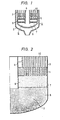
- Fig. 1 shows the construction of a lower section of the intermediate heat exchanger disclosed in Japanese Utility Model Laid-Open No. 42690/ 1981.
- the sodium in a primary cooling system, which is introduced into an outer cylinder 2 flows downward in an inner cylinder 3.
- the sodium in a secondary cooling system which flows downward in a downwardly-extending tube 4, enters a lower plenum 6 defined by the inner cylinder 3 and a lower tube plate 5, to be more precise, a region 8, which is in the lower plenum 6 and below a current-setting plate 7 having a plurality of bores.
- the sodium in the secondary cooling system then passes through the bores in the current-setting plate 7 to enter a region 9, which is in the plenum 6 and above the current-setting plate 7, the sodium being then distributed into heat transfer tubes 10 fixed to the lower tube plate 5.
- FIG. 2 The flowing condition of the sodium in the lower plenum 6 in the lower section of the intermediate heat exchanger 1 is shown in Fig. 2.
- Reference numeral 11 denotes a heat shielding member, which is not shown in Fig. 1, and which is formed so as to surround the downwardly extending tube. Since the intermediate heat exchanger 1 is provided with the current-setting plate 7 in the lower plenum 6 therein, the sodium flows uniformly in the region 9 therein. Accordingly, the flow rates of the sodium supplied into the heat transfer tubes 10 become substantially equal. In fact, a ratio (deviation value) 6max of an average value Vo of the velocities Vi of flow of the sodium passing through the heat transfer tubes 10 to a maximum value Vmax of the velocities Vi of flow of the sodium is 1.15.
- the 6max represents a deviation value of the flow rates of the sodium.
- a vortex 12 of the sodium which is discharged from the downcommer tube 4, occurs in the region 8 in the lower plenum 6.
- a vortex 12 of the sodium in the lower plenum 6 causes the turbine trip. When the turbine trip occurs, a flow rate of the feed water supplied to a steam generator suddenly decreases. The vortex 12 of sodium also causes a decrease in a flow rate of the feed water while an operation of the fast breeder is interrupted. As a result, a high-cycle thermal impact is applied to the material forming the lower plenum 6.
- the sodium cooled in the steam generator and having a low temperature exists in the lower plenum 6.
- a low temperature about 320°C
- the high-temperature sodium (having a temperature of about 510°C), which is discharged from the steam generator in a substantially non-cooled state, flows into the region 8 in the lower plenum 6 through the downcommer tube 4.
- the low-temperature sodium is held in the region 8 before the high-temperature sodium has flowed thereinto.
- the high-temperature sodium ejected downward from the downwardly-extending tube 4 flows upward in the region 8 along a bottom surface of the cylinder 3 as shown in Fig. 2. Consequently, a vortex 12 occurs in the region 8. Due to the entry of the high-temperature sodium into the region 8, the low-temperature sodium therein does not flow out therefrom at once through the current-setting plate 7 but flows vertically in the region 8. As the high-temperature sodium flows into the region 8, the low-temperature sodium is scraped at a superficial portion thereof intermittently by the vortex 12. The low-temperature sodium thus scraped passes through the lower tube plate 5 with the high-temperature sodium to enter the heat transfer tubes 10.
- the velocity of flow of the scraped low-temperature sodium is high, it passes through the lower tube plate 5 at a low temperature, i.e. without being heated sufficiently by the high-temperature sodium.
- the low-temperature sodium and high-temperature sodium contact alternately in extremely short cycles the lower tube plate 4 and the portion of the inner surface of the inner cylinder 3 which defines the lower plenum. Accordingly, when the turbine trip occurs, high-cycle thermal impacts are applied to the bottom portion of the inner cylinder 3 and lower tube plate 4. The same applies while an operation of the fast breeder is interrupted.
- the inventors discussed various methods capable of reducing the high-cycle thermal impacts to minimize the thermal fatigue of the lower tube plate and a wall defining the lower plenum, and discovered that, when the sodium is ejected from the downwardly-extending tube in the radial direction, parallel currents thereof can be generated in the lower plenum with no vortex occurring therein.
- the present invention has been achieved on the basis of this discovery.
- the sodium heated in a core 31 in a reactor vessel 30 is introduced into an intermediate heat exchanger 15 through a pipe 32 in a primary cooling system by an operation of a pump 34, to be cooled with the sodium supplied into heat transfer tubes 10 in the intermediate heat exchanger 15 through a pipe 36 in a secondary cooling system.
- the sodium discharged from the intermediate heat exchanger 15 is returned to the reactor vessel 30 through a pipe 33 in the primary cooling system.
- the sodium is heated while it passes through the heat transfer tubes 10, to a temperature of about 320°C to about 510°C.
- the sodium of a temperature of about 510°C is sent to a steam generator 38 through a pipe 35 in the secondary cooling system.
- This sodium is cooled with the feed water supplied into heat transfer tubes 39 in the steam generator 38 through a feed water pipe 42, to be discharged into the pipe 36 in the second cooling system.
- Reference numeral 37 denotes a pump.
- the feed water flowing through the heat transfer tubes 39 in the steam generator 38 is heated with the sodium to turn into steam.
- the steam is sent to a turbine 43 through a main steam pipe 40.
- the steam discharged from the turbine 43 is made more dense in a condenser 44 to turn into water.
- This water is returned to the heat transfer tubes 39 by an operation of a feed water pump 47.
- a main steam value 45 is opened, while a by-pass valve 46 is closed.
- Reference numeral 41 denotes a by-pass pipe.
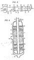
- the intermediate heat exchanger 15 consists of an outer cylinder 2, an inner cylinder 3 provided in the outer cylinder 2, lower and upper tube plates 5, 23 provided in the inner cylinder 3, a plurality of heat transfer tubes 10 joined at their respective both end portions to the lower and upper tube plates 5, 23, and a downwardly-extending tube 16 provided in the central portion of the inner cylinder 3.
- the downwardly-extending tube 16 is connected to the pipe 36 in the secondary cooling system to extend through the upper and lower tube plates 23, 5 and reach the interior of a lower plenum 6.
- the upper and lower tube plates 23, 5 are welded to the inner cylinder 3 and downwardly-extending tube 16 so as to prevent the sodium in the secondary cooling system in an upper plenum 24 and lower plenum 6 from flowing out into such a space in the inner cylinder 3 that is on the side of the primary cooling system.
- the downwardly-extending tube 16 contacts at its lower end a bottom portion of the inner cylinder 3. However, it is not strictly necessary that the lower end of the downwardly-extending tube 16 and the bottom portion of the inner cylinder 3 be in contact with each other; a clearance 34a may be provided therebetween as shown in Fig. 7.
- a plurality of bores 17 are provided in the portion of a side wall of the downwardly-extending tube 16 which is in the lower plenum 6 formed in such a portion of the interior of the inner cylinder 3 that is below the lower tube plate 5.
- the plural bores 17 are provided in the portion of the downwardly-extending tube 16 which is in the lower plenum 6 in such a manner that the bores 17 are arranged in the axial and circumferential directions of the tube 16.
- An inlet nozzle 18 provided in the outer cylinder 2 is connected to the primary cooling pipe 32, while an outlet nozzle 19 provided in the outer cylinder 2 is connected to the primary cooling pipe 33.
- An inlet 21 and an outlet 22 for sodium are provided at upper and lower portions of the inner cylinder 3.
- a partition member 20 is provided between the outer and inner cylinders 2, 3 in order to prevent the sodium from flowing in the outer cylinder 2 from the inlet nozzle 18 to the outlet nozzle 19 directly.
- Reference numeral 25 denotes support members for the heat transfer tubes 10.
- the sodium in the primary cooling system which flows from the inlet nozzle 18 into the outer cylinder 2, passes through the inlet 21 to enter the inner cylinder 3.
- the resulting sodium flows downward along the heat transfer tubes 10 to the outside of the cylinder 3 via the outlet 22, the sodium being then discharged from the outlet nozzle 19 into the primary cooling pipe 33.
- the sodium supplied from the secondary cooling pipe 36 flows downward in the downwardly-extending tube 16 to be ejected in the radial direction thereof from the plural bores 17.
- the clearance 34 (Fig. 7) and bores 17 constitute means for ejecting sodium in the radial direction of the downwardly-extending tube 16.
- the diameter of the bores 17 provided in the downwardly-extending tube 16 is the same with respect to the axial direction thereof.
- the flow rates of sodium ejected from such bores 17 that are provided in the portion of the downwardly-extending tube 16 which is closer to a lower end thereof become higher.
- the sodium ejected into the lower plenum 6 passes through the heat transfer tubes 10 to enter the upper plenum 24 provided above the upper tube plate 23, the sodium then flowing into the secondary cooling pipe 35.
- the flowing condition of the sodium in the lower plenum 6 in this embodiment is shown in Fig. 5.
- the sodium ejected from the bores 17 arranged in the downwardly-extending tube 16 in the axial direction thereof forms parallel currents as shown in Fig. 5, which flow horizontally (in the radial direction of the downwardly-extending tube 16) in the lower plenum 6 as they remain to be in parallel with one another, to thereafter turn into upward currents (flowing in the axial direction of the downwardly-extending tube 16). Therefore, no vortex of sodium occurs in the lower plenum 6.
- the lower plenum 6 has the functions of converting the downward currents of sodium in the downwardly-extending tube 16 into upward currents thereof.
- the sodium in the secondary cooling system is not cooled in the steam generator 38.
- the sodium in the secondary cooling system is ejected as it remains to have a high temperature (about 510°C), into the lower plenum 6 through the downwardly-extending tube 16 to flow in parallel currents.
- the low-temperature sodium (having a temperature of about 320°C) held in the lower plenum 6 is pressed by the parallel currents of the high-temperature sodium toward the outside thereof.
- the degree of the thermal impact applied to the wall of the lower plenum 6 when the high-temperature sodium enters the plenum 6 is substantially equal to that of the thermal impact applied at such time as mentioned to the wall of the plenum in the conventional intermediate heat exchanger 1.
- the intermediate heat exchanger 15 no vortex of low-temperature sodium occurs in the lower plenum 6. Accordingly, unlike the intermediate heat exchanger 1, which receives high-cycle thermal impacts every time the operation of the fast breeder is interrupted, the intermediate heat exchanger 15 does not receive any thermal impacts. This allows the thermal fatigue of the intermediate heat .exchanger 15 to be reduced to a great extent.
- FIG. 6 The distribution of flow rates of sodium in the heat transfer tubes 10 in the radial direction of the intermediate heat exchanger 15 is shown in Fig. 6.
- Reference letter R denotes the diameter of the inner cylinder 3, and r a distance between the axis of the inner cylinder 3 and the axes of the heat transfer tubes 10.
- the 6max is 1.10, which indicates that the scatter of flow rates of the sodium flowing in the heat transfer tubes 10 in the intermediate heat exchanger 15 can be reduced to a greater extent than that in the intermediate heat exchanger 1.
- This embodiment can be made by merely extending a part of the downwardly-extending tube into the lower plenum 6; it has a very simple construction.
- the downwardly-extending tube 16 is set in such a manner that the tube 16 is in contact at its lower end with the bottom surface of the lower plenum 6, the vibration of the tube 16 can be prevented while the sodium is ejected from the bores 17 provided therein.
- a distance between the free end of the downwardly-extending tube 16 and the inner surface of the lower plenum 6 be set to not more than 10% of the height of the portion of the downwardly-extending tube 16 which is between the lower surface of the lower tube plate 5 shown in Fig. 4 and the bottom surface of the lower plenum 6 shown in the same figure.
- the mentioned distance is not less than 10% of the height of the portion referred to above of the tube 16, there is the possibility that a vortex of sodium occurs in the lower plenum 6.
- FIG. 8 shows another embodiment of an intermediate heat exchanger according to the present invention.
- This intermediate heat exchanger 30 is formed by providing a ring 31 having a plurality of bores 32 in the lower plenum 6 in the above intermediate heat exchanger 15.
- the ring 31 is fixed to the inner surface of an inner cylinder 3.
- the construction of the other portion of the heat exchanger 30 is identical with that of the intermediate heat exchanger 15.
- This embodiment permits obtaining the same effect as the intermediate heat exchanger 15.
- the flowing condition of the sodium in the lower plenum 6 in this embodiment is shown in Fig. 9. It is understood from the drawing that the flow of sodium to the heat transfer tubes 10 in a peripheral section of the interior of the inner cylinder 3 is restricted by the ring 31.
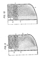
- FIG. 10 Still another embodiment of the present invention is shown in Fig. 10.
- the diameters of bores 17 gradually increase toward an upper portion of a lower plenum. Therefore, the flow rates of the sodium flowing out from these bores 17 become equal.
- This embodiment also permits obtaining the same effect as the intermediate heat exchanger 15.
- the 6max in this embodiment is 1.16.
- Fig. 11 shows the flowing condition of the sodium in a lower plenum in a further embodiment of the present invention.
- the diameters of upper bores 17 are greater than those in the embodiment shown in Fig. 9, so that the flow rates of the sodium ejected from the bores 17 gradually increased toward an upper portion of a lower plenum.
- This embodiment also permits obtaining the same effect as the intermediate heat exchanger 15.
- the ⁇ max in this embodiment is 1.18.
- the diameters of the bores 17 to be provided in the downwardly-extending tube 16 may be set in such a manner that the bores 17 formed between a lower end of the tube 16 and a predetermined position thereon, which has a certain height above the lower end of the tube 16, have the same diameter with the remaining bores 17, which is formed above the mentioned position, having such diameters that increase gradually in the upward direction.
- the flow rates of the sodium ejected therefrom increases gradually in the downward direction.
- the sodium ejected therefrom flows at a uniform rate.
- This embodiment also permits obtaining the same effect as the intermediate heat exchanger 15.
- the 6max in this embodiment is 1.12.
- Fig. 12 shows another example of a conventional heat exchanger for reference.
- This heat exchanger is formed by removing the current-setting plate from the conventional heat exchanger shown in Fig. 1.
- the intermediate heat exchanger shown in Fig. 12 has a 6max of 1.39.
- a vortex occurs in a lower plenum in this heat exchanger. Accordingly, the distribution of the flow rates of sodium in this example become uneven, so that high-cycle thermal impacts are also applied to the wall of a lower plenum.
- the embodiments described above of the present invention are far superior to this example.
- the constructional members permit minimizing the high-cycle thermal impacts applied thereto, so that the thermal fatigue thereof can be reduced to a great extent.
Claims (6)
Applications Claiming Priority (2)
| Application Number | Priority Date | Filing Date | Title |
|---|---|---|---|
| JP39491/82 | 1982-03-15 | ||
| JP57039491A JPS58158498A (ja) | 1982-03-15 | 1982-03-15 | 熱交換器 |
Publications (2)
| Publication Number | Publication Date |
|---|---|
| EP0089027A1 EP0089027A1 (fr) | 1983-09-21 |
| EP0089027B1 true EP0089027B1 (fr) | 1986-06-11 |
Family
ID=12554516
Family Applications (1)
| Application Number | Title | Priority Date | Filing Date |
|---|---|---|---|
| EP83102421A Expired EP0089027B1 (fr) | 1982-03-15 | 1983-03-11 | Echangeur de chaleur |
Country Status (4)
| Country | Link |
|---|---|
| US (1) | US4602682A (fr) |
| EP (1) | EP0089027B1 (fr) |
| JP (1) | JPS58158498A (fr) |
| DE (1) | DE3364017D1 (fr) |
Families Citing this family (6)
| Publication number | Priority date | Publication date | Assignee | Title |
|---|---|---|---|---|
| US5323851A (en) * | 1993-04-21 | 1994-06-28 | Wynn's Climate Systems, Inc. | Parallel flow condenser with perforated webs |
| US7140328B2 (en) * | 2002-03-11 | 2006-11-28 | Ztek Corporation | Miniature vaporizers for use with chemical converters and energy devices |
| PL2174075T3 (pl) * | 2007-07-05 | 2012-02-29 | Ib Ntec | System termodynamiczny stosujący urządzenie do wytwarzania ciepła przez cyrkulację czynnika pod ciśnieniem przez liczne przewody rurowe |
| US11306978B2 (en) * | 2014-09-05 | 2022-04-19 | 2078095 Ontario Limited | Heat recovery apparatus and method |
| CN106871672B (zh) * | 2017-02-22 | 2019-08-06 | 广州力润机电设备有限公司 | 一种高效节能的直通形状的热交换结构 |
| US11859832B2 (en) | 2021-06-22 | 2024-01-02 | 2078095 Ontario Limited | Gray water heat recovery apparatus and method |
Family Cites Families (18)
| Publication number | Priority date | Publication date | Assignee | Title |
|---|---|---|---|---|
| US2097602A (en) * | 1936-03-06 | 1937-11-02 | Warren Webster & Co | Radiator |
| FR1253859A (fr) * | 1959-12-29 | 1961-02-17 | France Etat | Perfectionnements apportés aux installations nucléaires de puissance |
| GB1027195A (en) * | 1963-11-07 | 1966-04-27 | Metallurg Engineers Ltd | Improvements in heat exchangers |
| US3437077A (en) * | 1966-01-21 | 1969-04-08 | Babcock & Wilcox Co | Once-through vapor generator |
| FR1511662A (fr) * | 1966-12-23 | 1968-02-02 | Commissariat Energie Atomique | Réacteur nucléaire refroidi par un liquide |
| US3827484A (en) * | 1970-02-04 | 1974-08-06 | W Wolowodiuk | Liquid metal heat exchanger |
| US3812824A (en) * | 1971-03-04 | 1974-05-28 | Foster Wheeler Corp | Sodium-heated steam generator |
| US3776302A (en) * | 1972-02-14 | 1973-12-04 | Westinghouse Electric Corp | Tube and shell heat exchanger |
| US3776199A (en) * | 1972-05-05 | 1973-12-04 | Hy Way Heat Systems | Regenerative heat exchanger |
| JPS5746285B2 (fr) * | 1974-11-13 | 1982-10-02 | ||
| FR2391421A1 (fr) * | 1977-05-16 | 1978-12-15 | Commissariat Energie Atomique | Generateur de vapeur a circulation forcee |
| DE2725877A1 (de) * | 1977-06-08 | 1978-12-21 | Interatom | Waermetauscher fuer aggressive medien |
| FR2402176A2 (fr) * | 1977-09-05 | 1979-03-30 | Commissariat Energie Atomique | Echangeur de chaleur, notamment generateur de vapeur chauffe au sodium liquide |
| FR2452687A1 (fr) * | 1979-03-28 | 1980-10-24 | Stein Industrie | Echangeur de chaleur a zone centrale avec conduits coaxiaux et zone d'echange peripherique |
| JPS5642690A (en) * | 1979-09-14 | 1981-04-20 | Matsushita Electric Ind Co Ltd | Automatic page delivering device |
| JPS6324396Y2 (fr) * | 1980-08-25 | 1988-07-04 | ||
| JPS5929799B2 (ja) * | 1981-02-16 | 1984-07-23 | 株式会社東芝 | 熱交換器 |
| FR2509841B1 (fr) * | 1981-07-17 | 1986-07-18 | Creusot Loire | Perfectionnement aux generateurs de vapeur du type sodium-eau |
-
1982
- 1982-03-15 JP JP57039491A patent/JPS58158498A/ja active Granted
-
1983
- 1983-03-11 DE DE8383102421T patent/DE3364017D1/de not_active Expired
- 1983-03-11 EP EP83102421A patent/EP0089027B1/fr not_active Expired
- 1983-03-15 US US06/475,556 patent/US4602682A/en not_active Expired - Lifetime
Also Published As
| Publication number | Publication date |
|---|---|
| DE3364017D1 (en) | 1986-07-17 |
| JPS6337880B2 (fr) | 1988-07-27 |
| JPS58158498A (ja) | 1983-09-20 |
| US4602682A (en) | 1986-07-29 |
| EP0089027A1 (fr) | 1983-09-21 |
Similar Documents
| Publication | Publication Date | Title |
|---|---|---|
| US5161605A (en) | Tubular reactor and method | |
| US5464057A (en) | Quench cooler | |
| WO2007100041A1 (fr) | Separateur gaz-eau | |
| EP0089027B1 (fr) | Echangeur de chaleur | |
| US5419391A (en) | Steam generator with axial flow preheater | |
| US3830292A (en) | Flow distribution for heat exchangers | |
| US3706301A (en) | Integral economizer for u-tube generator | |
| JPH02195196A (ja) | 熱交換器 | |
| US4736713A (en) | Foraminous or perforated flow distribution plate | |
| US3766892A (en) | Split feed economizer | |
| EP2766661B1 (fr) | Faisceau de tubes pour générateur de vapeur anti-encrassement | |
| JPH0425441B2 (fr) | ||
| US3895674A (en) | Inlet flow distributor for a heat exchanger | |
| US3915123A (en) | Steam generator | |
| US4257356A (en) | Heat exchanging apparatus and method | |
| JPH039399B2 (fr) | ||
| US2138469A (en) | Heat exchanger | |
| US4057033A (en) | Industrial technique | |
| JPS62245095A (ja) | 熱交換器 | |
| US5978434A (en) | Pebble bed reactor | |
| JPS613999A (ja) | シエルアンドチユ−ブ型熱交換器 | |
| JPS631516B2 (fr) | ||
| JPS6284298A (ja) | 熱交換器のバツフル板構造 | |
| JPS61285390A (ja) | 熱交換器 | |
| JPS629199A (ja) | 熱交換器 |
Legal Events
| Date | Code | Title | Description |
|---|---|---|---|
| PUAI | Public reference made under article 153(3) epc to a published international application that has entered the european phase |
Free format text: ORIGINAL CODE: 0009012 |
|
| AK | Designated contracting states |
Designated state(s): DE FR GB |
|
| 17P | Request for examination filed |
Effective date: 19840320 |
|
| GRAA | (expected) grant |
Free format text: ORIGINAL CODE: 0009210 |
|
| AK | Designated contracting states |
Kind code of ref document: B1 Designated state(s): DE FR GB |
|
| REF | Corresponds to: |
Ref document number: 3364017 Country of ref document: DE Date of ref document: 19860717 |
|
| ET | Fr: translation filed | ||
| PLBE | No opposition filed within time limit |
Free format text: ORIGINAL CODE: 0009261 |
|
| STAA | Information on the status of an ep patent application or granted ep patent |
Free format text: STATUS: NO OPPOSITION FILED WITHIN TIME LIMIT |
|
| 26N | No opposition filed | ||
| PGFP | Annual fee paid to national office [announced via postgrant information from national office to epo] |
Ref country code: DE Payment date: 19980529 Year of fee payment: 16 |
|
| PG25 | Lapsed in a contracting state [announced via postgrant information from national office to epo] |
Ref country code: DE Free format text: LAPSE BECAUSE OF NON-PAYMENT OF DUE FEES Effective date: 20000101 |
|
| PGFP | Annual fee paid to national office [announced via postgrant information from national office to epo] |
Ref country code: FR Payment date: 20010316 Year of fee payment: 19 |
|
| REG | Reference to a national code |
Ref country code: GB Ref legal event code: IF02 |
|
| PGFP | Annual fee paid to national office [announced via postgrant information from national office to epo] |
Ref country code: GB Payment date: 20020301 Year of fee payment: 20 |
|
| PG25 | Lapsed in a contracting state [announced via postgrant information from national office to epo] |
Ref country code: FR Free format text: LAPSE BECAUSE OF NON-PAYMENT OF DUE FEES Effective date: 20021129 |
|
| REG | Reference to a national code |
Ref country code: FR Ref legal event code: ST |
|
| PG25 | Lapsed in a contracting state [announced via postgrant information from national office to epo] |
Ref country code: GB Free format text: LAPSE BECAUSE OF EXPIRATION OF PROTECTION Effective date: 20030310 |
|
| REG | Reference to a national code |
Ref country code: GB Ref legal event code: PE20 |