EP0088736A2 - Prefabricated central installation for electrically activated water supply - Google Patents
Prefabricated central installation for electrically activated water supply Download PDFInfo
- Publication number
- EP0088736A2 EP0088736A2 EP83830048A EP83830048A EP0088736A2 EP 0088736 A2 EP0088736 A2 EP 0088736A2 EP 83830048 A EP83830048 A EP 83830048A EP 83830048 A EP83830048 A EP 83830048A EP 0088736 A2 EP0088736 A2 EP 0088736A2
- Authority
- EP
- European Patent Office
- Prior art keywords
- water
- central control
- electric valves
- pipe
- unit
- Prior art date
- Legal status (The legal status is an assumption and is not a legal conclusion. Google has not performed a legal analysis and makes no representation as to the accuracy of the status listed.)
- Withdrawn
Links
Images
Classifications
-
- E—FIXED CONSTRUCTIONS
- E03—WATER SUPPLY; SEWERAGE
- E03C—DOMESTIC PLUMBING INSTALLATIONS FOR FRESH WATER OR WASTE WATER; SINKS
- E03C1/00—Domestic plumbing installations for fresh water or waste water; Sinks
- E03C1/02—Plumbing installations for fresh water
- E03C1/021—Devices for positioning or connecting of water supply lines
- E03C1/023—Devices for positioning or connecting of water supply lines with flow distribution, e.g. diverters
Definitions
- the hydraulic installations of the abitation houses and similar buildings consist of galvanized steel pipes, inserted inside the structure of the building and provided with interceptors for each unit of use as sinks, baths, showers, appliances and similar units.
- the installation of these installations requires an expensive work of cutting, threading, assembly and lining of said steel pipes, which are moreover constrained to rectilinear paths connected by curves which form a predetermined and non-variable angle.
- the temperature is adjusted by mixing valves installed near the water distribution point, making it necessary to supply two independent pipes for hot water and for each point of use. cold water.
- the installation of the invention which comprises a general central control and distribution box, to which the pipes of the cold and hot water network terminate. From this box connect the supply lines to each unit of use near the which one or more terminal water control and distribution boxes are installed.
- the regulation of the flow and the mixing of the water for the regulation of the temperature are carried out, for each unit of use, by means of groups of electric, normal or modulating valves, placed inside said general central box.
- control and distribution supplied with hot and cold water by the said network pipes, and which can be actuated either one by one or in combination, these groups of electric valves being supplied with low voltage current (for example at 12 V).
- Each supply unit supply line includes at least one flexible hose for the passage of water and a group of conveniently insulated electrical conductors for the remote control of the corresponding electrical valves, all inserted in a flexible sheath suitable to be fitted inside the masonry works of the building where the installation is set up.
- a cold water collecting pipe and a hot water collecting pipe are installed, both possibly fitted with interception valves and inlet filters.
- To the cold water collector are connected the inlet pipes of the electric valves for regulating the flow of cold water, while to the hot water collector are connected the inlet pipes of the electric valves to regulate the flow of hot water.
- the outlet pipes of the hot and cold water electric valves of each user unit lead to a single pipe, inserted inside the flexible supply pipe to the user unit itself.
- the units which use water at constant flow rate are directly connected to a manifold by means of the corresponding flexible hose, but it is possible to provide for the presence of an electric interception valve between manifold and piping also for each of these units, like sanitary installations, washing machines, dishwashers and similar units, in order to prevent the corresponding flexible supply hoses from remaining under pressure when the interceptor valve usually placed on these units is closed.
- each flexible pipe leaving the general central control and distribution box near the corresponding point of use, such as sink, shower, baths and similar units, there are one or more terminal boxes, in which are contained a hose for the distribution of water and the electric selectors for the control of opening and closing of the electric valves, normal or with modulation, present in the central central box of control and distribution and relating to the corresponding unit of use, in the combination chosen to dispense water at the desired flow and temperature.
- the general central control and distribution box provides the possibility of being connected to a stand-alone generator or an emergency battery, to cope with sudden interruptions in the supply of electrical energy.
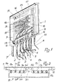
- FIG. 1 shows an embodiment of the hydraulic installation according to the invention, essentially constituted by a general central control and distribution box 1 and by a plurality of pipes for connection to the units 2, 3, 4, 5, 6, etc.
- the general central control and distribution box 1 consists of a box to be installed in a room in the user's apartment. To said box are connected the hot water supply lines 7 and cold water 8 usually made of galvanized iron pipe, which are connected to the two collectors 9 and 10 present inside. These collectors 9 and 10 are equipped with interception valves 11 and 12, which make it possible to isolate the interior prefabricated installation of the mains water pipes 7 and 8.
- a pusher 15 which acts on the control of the user unit at the lowest level relative to the general box. control center and distribution (for example the bidet) and which allows the drainage of all the water contained in the pipes.
- the general central control and distribution box 1 contains a number of electric valves, for each unit of use which needs water with variable flow and temperature, such as sinks, baths, showers and similar units, and the connections of the collector for the direct uses of cold water, not regulated in flow, like sanitary installations, washing machines and similar units. These units of use can however be equipped, if one did not wish to leave under pressure the pipe of the corresponding pipe of the general central box of control and distribution to the unit of use, of a valve each for the interception of the pipe even near the manifold.
- each unit for using hot and cold water (for example that supplied by line 2) is provided with a series of electric valves connected to the cold water collector 9 ( in the example four in number), generally indicated with 16 in the drawing of Figure 1, and correspondingly electric valves connected to the hot water collector 10, indicated with 17 in the same Figure 1.
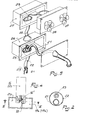
- Said electrical valves 16 and 17 can advantageously be grouped, for each unit of use, in a single block 18, as is produced in the example illustrated in Figures 3 and 4, in which there are two inlet chambers separated 19a and 19b, supplied respectively by the cold water collector 9 and by the hot water collector 10, which can be brought into communication with the outlet chamber 20 by means of the opening of the shutter 16 'd one of the valves 16a, 16b, 16c, 16d (or 17a, 17b, 17c, 17d), or an appropriate combination of more than one of said electrical valves, which, as shown in Figure 3, may have different cross sections from one another.
- To the chamber 20 is connected the pipe which carries the mixed water and regulated in flow rate to the unit of use (for example by line 2).
- the general central control and distribution box 1 also contains the transformer 24 which supplies the supply voltage to the electric valves, which is connected to the electrical network by means of the general supply cable 25. Inside the box general control and distribution center is also provided housing for an emergency battery, or terminals for connection to another source of energy, to obviate possible interruptions in the supply of electrical energy.
- the water distribution box 26 and the electric control box for the electric valves 27 are installed. This control is carried out by handles, sliders, levers or by similar means, as required. and the wishes of the user.
- the electric cable 23 passes through, in the illustrated embodiment, the box 26 and it splits in the box 27 by separating the selection wires of the electric valves of hot water from those of the electric valves of cold water.
Abstract
Description
Les installations hydrauliques des maisons d'abitation et de bâtiments semblables sont constituées par des tuyauteries en acier zingué, inserées à l'interieur de la structure du bâti ment et munies d'organes d'interception pour chaque unité de utilisation comme éviers, baignoires, douches, appareils électroménagers et unités semblables. La mise en place de ces installations exige un coûteux travail de coupe, de filetage, de montage et de garnissage des dites tuyauteries en acier, qui sont de plus contraintes à des tracés rectilignes raccordés par courbes qui forment un angle prédéterminé et non variable.The hydraulic installations of the abitation houses and similar buildings consist of galvanized steel pipes, inserted inside the structure of the building and provided with interceptors for each unit of use as sinks, baths, showers, appliances and similar units. The installation of these installations requires an expensive work of cutting, threading, assembly and lining of said steel pipes, which are moreover constrained to rectilinear paths connected by curves which form a predetermined and non-variable angle.
L'emploi de tuyauteries métalliques présente en outre le danger de corrosion et de perçage, avec des dommages importants et des coûteuses interventions aux ouvrages de maçonnerie où le tuyau est inséré.The use of metal pipes also presents the danger of corrosion and drilling, with significant damage and costly interventions to the masonry works where the pipe is inserted.
Dans les installations traditionelles le réglage de la tempéra ture est obtenu par des soupapes de mélange installées près du point de distribution de l'eau, en rendant nécessaire d'amener à chaque point d'utilisation deux tuyauteries indépendentes pour l'eau chaude et pour l'eau froide. Il résulte en outre difficile d'obtenir chaque fois un débit constant en portée et en température.In traditional installations, the temperature is adjusted by mixing valves installed near the water distribution point, making it necessary to supply two independent pipes for hot water and for each point of use. cold water. In addition, it is difficult to obtain a constant flow rate in range and temperature each time.
Ces et autres problèmes sont résolus par l'installation de la invention, qui comprend une boîte générale centrale de commande et de distribution, à laquelle aboutent les tuyauteries du réseau d'eau froide et chaude. De ce boîte branchent les con duites d'adduction à chaque unité d'utilisation près de la quelle sont installées une ou plusieurs boîtes terminales de commande et de distribution de l'eau. Le réglage du débit et le mélange de l'eau pour le réglage de la température sont réalisés, pour chaque unité d'utilisation, au moyen de groupes de soupapes électriques, normaux ou à modulation, placées à l'interieur de ladite boîte générale centrale de commande et de distribution, alimentées avec de l'eau chaude et froide par les dites tuyauteries du réseau, et qui peuvent être actionnées soit une par une soit en combinaison, ces groupes de soupapes électriques étant alimentées avec de la courant à basse tension (par exemple à 12 V).These and other problems are solved by the installation of the invention, which comprises a general central control and distribution box, to which the pipes of the cold and hot water network terminate. From this box connect the supply lines to each unit of use near the which one or more terminal water control and distribution boxes are installed. The regulation of the flow and the mixing of the water for the regulation of the temperature are carried out, for each unit of use, by means of groups of electric, normal or modulating valves, placed inside said general central box. control and distribution, supplied with hot and cold water by the said network pipes, and which can be actuated either one by one or in combination, these groups of electric valves being supplied with low voltage current ( for example at 12 V).
Chaque conduite d'adduction à une unité d'utilisation comprend au moins un tuyau flexible pour le passage de l'eau et un groupe de conducteurs électriques opportunément isolés pour la commande à distance des soupapes électriques correspondantes, le tout inséré dans une gaine souple apte à être emboîtée à l'interieur des ouvrages de maçonnerie du bâtiment où l'installation est mise en place.Each supply unit supply line includes at least one flexible hose for the passage of water and a group of conveniently insulated electrical conductors for the remote control of the corresponding electrical valves, all inserted in a flexible sheath suitable to be fitted inside the masonry works of the building where the installation is set up.
A l'interieur de ladite boîte générale centrale de commande et de distribution sont installés un tuyau collecteur d'eau froide et un tuyau collecteur d'eau chaude, les deux éventuellement doués de soupapes d'interception et de filtres en entrée. Au collecteur de l'eau froide sont raccordées les conduites de entrée des soupapes électriques de réglage du débit de l'eau froide, tandis que au collecteur de l'eau chaude sont raccordées les conduites d'entrée des soupapes électriques de réglage du débit de l'eau chaude. Les conduites de sortie des soupapes électriques de l'eau chaude et froide de chaque unité d'utili sation aboutent à un tuyau unique, inséré à l'interieur de la conduite flexible d'adduction à l'unité d'utilisation même.Inside said general central control and distribution box, a cold water collecting pipe and a hot water collecting pipe are installed, both possibly fitted with interception valves and inlet filters. To the cold water collector are connected the inlet pipes of the electric valves for regulating the flow of cold water, while to the hot water collector are connected the inlet pipes of the electric valves to regulate the flow of hot water. The outlet pipes of the hot and cold water electric valves of each user unit lead to a single pipe, inserted inside the flexible supply pipe to the user unit itself.
Les unités qui utilisent de l'eau à débit constant sont directe ment raccordées à un collecteur au moyen du correspondant tuyau flexible, mais l'on peut prévoir la présence d'une soupape élec trique d'interception entre collecteur et tuyauterie aussi pour chacune de ces unités, comme installations sanitaires, machines à laver, lave-vaisselles et unités semblables, dans le but de éviter que les correspondants tuyaux flexibles d'adduction restaient sous pression à la fermeture de la soupape d'inter ception placée usuellement sur ces unités.The units which use water at constant flow rate are directly connected to a manifold by means of the corresponding flexible hose, but it is possible to provide for the presence of an electric interception valve between manifold and piping also for each of these units, like sanitary installations, washing machines, dishwashers and similar units, in order to prevent the corresponding flexible supply hoses from remaining under pressure when the interceptor valve usually placed on these units is closed.
A l'extrémité de chaque conduite flexible sortante de la boîte générale centrale de commande et de distribution, à proximité du correspondant point d'utilisation, comme évier, douche, bai gnoires et unités semblables, sont présentes une ou plusieurs boîtes terminales, dans lesquelles sont contenus un tuyau pour la distribution de l'eau et les sélecteurs électriques pour la commande d'ouverture et de fermeture des soupapes électriques, normaux ou à modulation, présentes dans la boîte générale cen trale de commande et de distribution et relatives à l'unité de utilisation correspondante, dans la combinaison choisie pour distribuer l'eau au débit et à la température désirées.At the end of each flexible pipe leaving the general central control and distribution box, near the corresponding point of use, such as sink, shower, baths and similar units, there are one or more terminal boxes, in which are contained a hose for the distribution of water and the electric selectors for the control of opening and closing of the electric valves, normal or with modulation, present in the central central box of control and distribution and relating to the corresponding unit of use, in the combination chosen to dispense water at the desired flow and temperature.
La boîte générale centrale de commande et de distribution prévoit la possibilité d'être connectée à un générateur autonome ou à une batterie d'urgence, pour faire face à des interruptions soudaines dans la fourniture d'énergie électrique.The general central control and distribution box provides the possibility of being connected to a stand-alone generator or an emergency battery, to cope with sudden interruptions in the supply of electrical energy.
Une description plus détaillée d'un exemple de réalisation de l'invention fait référence aux dessins annexés, dans lesquels:
- la Figure 1 montre une vue d'ensemble de la boite générale cen trale de commande ec de distribution, partie en coupe,
- la Figure 2 est une coupe de la conduite flexible d'eau et de commande électrique,
- les Figures 3 et 4 sont deux coupes d'un groupe de soupapes électriques réglantes le débit et la température pour une unité d'utilisation,
- la Figure 5 est une vue des boîtes terminales d'une conduite.
- FIG. 1 shows an overall view of the general central control ec distribution box, part in section,
- FIG. 2 is a section of the flexible water and electrical control pipe,
- Figures 3 and 4 are two sections of a group of electric valves regulating the flow rate and the temperature for a unit of use,
- Figure 5 is a view of the end boxes of a pipe.
Les dessins annexés montrent un exemple de réalisation de l'in stallation hydraulique selon l'invention, constituée essentielle ment par une boîte générale centrale de commande et de distribu tion 1 et par une pluralité de conduites de connexion aux unités 2, 3, 4, 5, 6, etc.The accompanying drawings show an embodiment of the hydraulic installation according to the invention, essentially constituted by a general central control and
La boite générale centrale de commande et de distribution 1 est constituée par un coffret à installer dans un local de l'apparte ment de l'usager. A ladite boîte sont raccordées les conduites d'adduction de l'eau chaude 7 et froide 8 usuellement réalisées en tuyau de fer zingué, qui sont raccordées aux deux collecteurs 9 et 10 présents à l'interieur. Ces collecteurs 9 et 10 sont doués de soupapes d'interception 11 et 12, qui permettent d'iso ler l'intière installation préfabriquée des conduites d'eau de réseau 7 et 8.The general central control and
Ils sont en outre insérés sur lesdits collecteurs les filtres 13 et 14, qu'on peut emporter pour un nettoyage périodique.They are also inserted on said
Pour éviter que pendant des interventions d'entretien on ait de l'écoulement d'eau des collecteurs, il est prévu un poussoir 15 qui agit sur la commande de l'unité d'utilisation à niveau le plus bas par rapport à la boîte générale centrale de commande et de distribution (par exemple le bidet) et qui permet l'écou lement de toute l'eau contenue dans les conduites.To avoid that during maintenance interventions there is a flow of water from the collectors, there is provided a
La boîte générale centrale de commande et de distribution 1 contient un certain nombre de soupapes électriques, pour chaque unité d'utilisation qui ait besoin d'eau à débit et température variables, comme éviers, baignoires, douches et unités sembla bles,et les connexions du collecteur pour les utilisations directes d'eau froide, non réglées en débit, comme installations sanitaires, machines à laver et unités semblables. Ces unités d'utilisation peuvent toutefois être douées, si l'on ne désirait pas de laisser sous pression le tuyau de la correspondante conduite de la boîte générale centrale de commande et de distri bution à l'unité d'utilisation, d'une soupape électrique chacune pour l'interception du tuyau même près du collecteur.The general central control and
Dans la forme de réalisation illustrée à la Figure 1, chaque unité d'utilisation d'eau chaude et froide (par exemple celle alimentée par la conduite 2) est douée d'une série de soupapes électriques raccordées au collecteur d'eau froide 9 (dans l'exem ple au nombre de quatre), globalement indiquées avec 16 au dessin de la Figure 1, et d'autant soupapes électriques raccordées au collecteur d'eau chaude 10, indiquées avec 17 à la même Figure 1.In the embodiment illustrated in FIG. 1, each unit for using hot and cold water (for example that supplied by line 2) is provided with a series of electric valves connected to the cold water collector 9 ( in the example four in number), generally indicated with 16 in the drawing of Figure 1, and correspondingly electric valves connected to the
Les dites soupapes électriques 16 et 17 peuvent être avantageuse ment groupées, pour chaque unité d'utilisation, dans un bloc unique 18, comme il est réalisé dans l'exemple illustré aux Figures 3 et 4, dans lesquelles on a deux chambres d'entrée séparées 19a et 19b, alimentées respectivement par le collecteur d'eau froide 9 et par le collecteur d'eau chaude 10, qui peuvent être mises en communication avec la chambre de sortie 20 au moyen de l'ouverture de l'obturateur 16' d'une des soupapes électriques 16a, 16b, 16c, 16d (ou 17a, 17b, 17c, 17d), ou d'une appropriée combinaison de plus d'une des dites soupapes électri ques, lesquelles, comme il est illustré à la Figure 3, peuvent avoir des différentes sections de passage l'une de l'autre. A la chambre 20 est raccordé le tuyau qui porte l'eau mélangée et réglée en débit à l'unité d'utilisation (par exemple par la conduite 2).L'ouverture d'une appropriée combinaison des soupa pes électriques 16a, 16b, 16c, 16d et 17a, 17b, 17c, 17d, chacune ayante une section de passage appropriée, permet d'obtenir les valeurs de débit et de température desirées. Ledit tuyau 21 et les analogues correspondants aux autres unités d'utilisation sont insérés chacun dans une gaine extérieure 22, souple, apte à être posée sous le plancher ou à l'interieur de bétonnages ou à l'interieur de parois dans le lieu de mise en place. Ce gaine est de dimension à pouvoir recevoir aussi la ligne électrique 23 qui contient les câbles de commande des soupapes électriques.Said
La boîte générale centrale de commande et de distribution 1 contient en outre le transformateur 24 qui fournit la tension d'alimentation aux soupapes électriques, lequel est connecté au réseau électrique au moyen du câble général d'alimentation 25. A l'interieur de la boîte générale centrale de commande et de distribution est en outre prévu le logement pour une batterie d'urgence, ou des bornes de connexion à un autre source d'éner gie, pour obvier à des éventuelles interruptions de la fourni ture d'énergie électrique.The general central control and
Près du point d'utilisation ils sont installés la boîte de distribution d'eau 26 et la boîte de commande électrique des soupapes électriques 27. Ce commande est réalisée par des poignées, des curseurs, des leviers ou par des moyens semblables, selon les exigences et le désirs de l'usager.Near the point of use, the
C'est naturellement possible de conglober les commandes électriques et le raccord de distribution d'eau dans un unique groupe (non illustré), avec une boîte de distribution unique, selon les exigences de mise en place.It is of course possible to combine the electrical controls and the water distribution connection into a single group (not shown), with a single distribution box, depending on the installation requirements.
Le câble électrique 23 traverse, dans la forme de réalisation illustrée, la boîte 26 et il se dédouble dans la boîte 27 en séparant les fils de sélection des soupapes électriques de l'eau chaude de ceux des soupapes électriques de l'eau froide.The
La rotation d'une ou des deux poignées ou un déplacement ana logue d'autres moyens de sélection permet de choisir le nombre de soupapes électriques à ouvrir, en obtenant la combinaison qui procure le débit désiré.The rotation of one or two handles or an analogous movement of other selection means makes it possible to choose the number of electric valves to open, obtaining the combination which provides the desired flow.
Il est possible d'employer des gaines extérieures 22 de diamètre majoré au cas où l'on prévoit des expansions futures de l'in stallation qui exigeraient des points d'utilisation ultérieurs. Il sera alors possible d'introduire dans la boite générale centrale de commande et de distribution un nouveau groupe de soupapes électriques et de passer dans la gaine 22 existante un nouveau tuyau flexible et un nuveau câble de commande, pour un nouveau point d'utilisation placé à proximité du débouché du tuyau précédent 21, en minimisant donc les travaux de maçonnerie nécessaires pour un agrandissement d'installation pareil.It is possible to use
Dans le domaine du schéma de réalisation illustré ils sont possibles des nombreuses variantes constructives, dans le but d'adapter l'installation à des particulières exigences de mise en place, par exemple en augmentant ou en diminuant le nombre des composantes employées, comme tuyaux, câbles, soupapes électriques ou en variant la forme et la sorte des matériaux employés. Ces modifications, et autres encore, ne sortent pas des limites de l'invention ainsi que décrite et illustrée dans ses caractéristiques généraux.In the area of the illustrated embodiment, numerous constructive variants are possible, with the aim of adapting the installation to particular installation requirements, for example by increasing or decreasing the number of components used, such as pipes, cables, electric valves or by varying the form and the kind of materials employees. These modifications, and others still, do not depart from the limits of the invention as described and illustrated in its general characteristics.
Claims (4)
Applications Claiming Priority (2)
| Application Number | Priority Date | Filing Date | Title |
|---|---|---|---|
| IT2001082 | 1982-03-08 | ||
| IT20010/82A IT1149793B (en) | 1982-03-08 | 1982-03-08 | PREFABRICATED CENTRALIZED HYDRAULIC SYSTEM WITH ELECTRIC CONTROL |
Publications (2)
| Publication Number | Publication Date |
|---|---|
| EP0088736A2 true EP0088736A2 (en) | 1983-09-14 |
| EP0088736A3 EP0088736A3 (en) | 1984-10-31 |
Family
ID=11163092
Family Applications (1)
| Application Number | Title | Priority Date | Filing Date |
|---|---|---|---|
| EP83830048A Withdrawn EP0088736A3 (en) | 1982-03-08 | 1983-03-04 | Prefabricated central installation for electrically activated water supply |
Country Status (2)
| Country | Link |
|---|---|
| EP (1) | EP0088736A3 (en) |
| IT (1) | IT1149793B (en) |
Cited By (5)
| Publication number | Priority date | Publication date | Assignee | Title |
|---|---|---|---|---|
| GB2172413A (en) * | 1985-03-12 | 1986-09-17 | Crosweller & Co Ltd W | Water supply installation for ablutionary purposes |
| US6076204A (en) * | 1994-08-11 | 2000-06-20 | Research Foundation Of State University Of New York | Modular bathing unit |
| WO2003023155A1 (en) * | 2001-09-13 | 2003-03-20 | Paolo Andreotti | Withdrawable single-pipe sanitary system |
| EP2468964A1 (en) * | 2010-12-23 | 2012-06-27 | Ideal Standard International BVBA | Modular flush-mounted system with a central flush-mounted mixed module |
| EP2468966A1 (en) * | 2010-12-23 | 2012-06-27 | Ideal Standard International BVBA | Flush-mounted fitting box comprising a mixed module with an electronically controllable temperature and volume control unit |
Citations (3)
| Publication number | Priority date | Publication date | Assignee | Title |
|---|---|---|---|---|
| DE1104450B (en) * | 1955-12-31 | 1961-04-06 | Elektro Hydraulik A Knoll | Water consumption system with electric solenoid valves built into the water pipe |
| DE2535076A1 (en) * | 1975-08-06 | 1977-02-17 | Paolo Bosi | Water supply distribution and dispensing system - has water container and flow distribution controls powered by low voltage system |
| FR2426202A1 (en) * | 1978-05-18 | 1979-12-14 | Meunier Jean Pierre | Junction box for water supply stop cocks - facilitates maintenance by indicating function of each stop cock |
-
1982
- 1982-03-08 IT IT20010/82A patent/IT1149793B/en active
-
1983
- 1983-03-04 EP EP83830048A patent/EP0088736A3/en not_active Withdrawn
Patent Citations (3)
| Publication number | Priority date | Publication date | Assignee | Title |
|---|---|---|---|---|
| DE1104450B (en) * | 1955-12-31 | 1961-04-06 | Elektro Hydraulik A Knoll | Water consumption system with electric solenoid valves built into the water pipe |
| DE2535076A1 (en) * | 1975-08-06 | 1977-02-17 | Paolo Bosi | Water supply distribution and dispensing system - has water container and flow distribution controls powered by low voltage system |
| FR2426202A1 (en) * | 1978-05-18 | 1979-12-14 | Meunier Jean Pierre | Junction box for water supply stop cocks - facilitates maintenance by indicating function of each stop cock |
Cited By (9)
| Publication number | Priority date | Publication date | Assignee | Title |
|---|---|---|---|---|
| GB2172413A (en) * | 1985-03-12 | 1986-09-17 | Crosweller & Co Ltd W | Water supply installation for ablutionary purposes |
| EP0195271A2 (en) * | 1985-03-12 | 1986-09-24 | CARADON MIRA LIMITED (formerly Walker Crosweller & Company Limited) | Water supply installation for ablutionary purposes |
| EP0195271A3 (en) * | 1985-03-12 | 1987-04-15 | CARADON MIRA LIMITED (formerly Walker Crosweller & Company Limited) | Water supply installation for ablutionary purposes |
| US6076204A (en) * | 1994-08-11 | 2000-06-20 | Research Foundation Of State University Of New York | Modular bathing unit |
| WO2003023155A1 (en) * | 2001-09-13 | 2003-03-20 | Paolo Andreotti | Withdrawable single-pipe sanitary system |
| EP2468964A1 (en) * | 2010-12-23 | 2012-06-27 | Ideal Standard International BVBA | Modular flush-mounted system with a central flush-mounted mixed module |
| EP2468966A1 (en) * | 2010-12-23 | 2012-06-27 | Ideal Standard International BVBA | Flush-mounted fitting box comprising a mixed module with an electronically controllable temperature and volume control unit |
| RU2578054C2 (en) * | 2010-12-23 | 2016-03-20 | Айдиел Стандард Интернэшнл Би-Ви-Би-Эй | Modular system of hidden installation with central mixing module of hidden installation |
| RU2578490C2 (en) * | 2010-12-23 | 2016-03-27 | Айдиел Стандард Интернэшнл Би-Ви-Би-Эй | Junction box of hidden installation for mixing module having temperature and flow control unit made as capable of electronic control |
Also Published As
| Publication number | Publication date |
|---|---|
| IT8220010A0 (en) | 1982-03-08 |
| EP0088736A3 (en) | 1984-10-31 |
| IT1149793B (en) | 1986-12-10 |
Similar Documents
| Publication | Publication Date | Title |
|---|---|---|
| US4352025A (en) | System for generation of electrical power | |
| EP0195271A2 (en) | Water supply installation for ablutionary purposes | |
| ZA200901070B (en) | Electricity generating arrangement | |
| EP0088736A2 (en) | Prefabricated central installation for electrically activated water supply | |
| US20140265328A1 (en) | Electricity generating arrangement | |
| AU2009214030A1 (en) | Energy supply device with energy panels in the form of roof tiles | |
| US2076650A (en) | House wiring system | |
| RU2578490C2 (en) | Junction box of hidden installation for mixing module having temperature and flow control unit made as capable of electronic control | |
| FR2467498A1 (en) | Domestic or commercial electricity supply installation - uses prefabricated distribution boxes with plug-in flexible cable | |
| DE3414510C3 (en) | Control device for fittings | |
| US2590147A (en) | Flush valve arrangement and installation | |
| GB2143559A (en) | Sanitary service unit | |
| RU2578054C2 (en) | Modular system of hidden installation with central mixing module of hidden installation | |
| WO2003023155A1 (en) | Withdrawable single-pipe sanitary system | |
| EP2503068A2 (en) | Sanitary or heating assembly with at least one electronically controlled fitting | |
| CN210946991U (en) | Centralized distributor | |
| US10972305B2 (en) | Power line communications network system for a spa | |
| CN217272190U (en) | Water separator hot melt connects | |
| DK149085B (en) | CONTROL FOR HEATERS IN HOT WATER CENTER HEATING SYSTEMS | |
| WO1983004425A1 (en) | System for generation of electrical power | |
| CN217279298U (en) | Lawn cleaning system | |
| GB2268942A (en) | Electrical control apparatus for flushing system | |
| CN212772611U (en) | Comprehensive energy box suitable for commercial complex multi-channel point location | |
| EP0128095B1 (en) | Ventilation system for a dwelling | |
| US5548522A (en) | Modular wiring and liquid ground |
Legal Events
| Date | Code | Title | Description |
|---|---|---|---|
| PUAI | Public reference made under article 153(3) epc to a published international application that has entered the european phase |
Free format text: ORIGINAL CODE: 0009012 |
|
| AK | Designated contracting states |
Designated state(s): BE DE FR GB NL SE |
|
| PUAL | Search report despatched |
Free format text: ORIGINAL CODE: 0009013 |
|
| AK | Designated contracting states |
Designated state(s): BE DE FR GB NL SE |
|
| 17P | Request for examination filed |
Effective date: 19850406 |
|
| 17Q | First examination report despatched |
Effective date: 19860128 |
|
| STAA | Information on the status of an ep patent application or granted ep patent |
Free format text: STATUS: THE APPLICATION IS DEEMED TO BE WITHDRAWN |
|
| 18D | Application deemed to be withdrawn |
Effective date: 19860607 |