EP0088569B1 - Multiple beam lens transducer for sonar systems - Google Patents
Multiple beam lens transducer for sonar systems Download PDFInfo
- Publication number
- EP0088569B1 EP0088569B1 EP83301041A EP83301041A EP0088569B1 EP 0088569 B1 EP0088569 B1 EP 0088569B1 EP 83301041 A EP83301041 A EP 83301041A EP 83301041 A EP83301041 A EP 83301041A EP 0088569 B1 EP0088569 B1 EP 0088569B1
- Authority
- EP
- European Patent Office
- Prior art keywords
- lens
- acoustic
- comprised
- medium
- transducers
- Prior art date
- Legal status (The legal status is an assumption and is not a legal conclusion. Google has not performed a legal analysis and makes no representation as to the accuracy of the status listed.)
- Expired - Lifetime
Links
- 230000001902 propagating effect Effects 0.000 claims description 14
- 239000013078 crystal Substances 0.000 claims description 9
- 239000000463 material Substances 0.000 claims description 7
- 239000004033 plastic Substances 0.000 claims description 6
- 229920003023 plastic Polymers 0.000 claims description 6
- 239000007787 solid Substances 0.000 claims description 6
- 229920002379 silicone rubber Polymers 0.000 claims description 5
- 239000004945 silicone rubber Substances 0.000 claims description 5
- XLYOFNOQVPJJNP-UHFFFAOYSA-N water Substances O XLYOFNOQVPJJNP-UHFFFAOYSA-N 0.000 claims description 4
- 239000004793 Polystyrene Substances 0.000 claims description 3
- 229910052751 metal Inorganic materials 0.000 claims description 3
- 239000002184 metal Substances 0.000 claims description 3
- 229920002223 polystyrene Polymers 0.000 claims description 3
- 239000004593 Epoxy Substances 0.000 claims description 2
- 239000004411 aluminium Substances 0.000 claims description 2
- 229910052782 aluminium Inorganic materials 0.000 claims description 2
- XAGFODPZIPBFFR-UHFFFAOYSA-N aluminium Chemical compound [Al] XAGFODPZIPBFFR-UHFFFAOYSA-N 0.000 claims description 2
- 230000005540 biological transmission Effects 0.000 description 3
- 238000010586 diagram Methods 0.000 description 3
- 238000009434 installation Methods 0.000 description 3
- 230000000694 effects Effects 0.000 description 2
- 229920001971 elastomer Polymers 0.000 description 2
- 239000000919 ceramic Substances 0.000 description 1
- 238000006243 chemical reaction Methods 0.000 description 1
- 230000003467 diminishing effect Effects 0.000 description 1
- 230000002349 favourable effect Effects 0.000 description 1
- 230000017525 heat dissipation Effects 0.000 description 1
- 230000000644 propagated effect Effects 0.000 description 1
- 230000001131 transforming effect Effects 0.000 description 1
Images

Classifications
-
- G—PHYSICS
- G10—MUSICAL INSTRUMENTS; ACOUSTICS
- G10K—SOUND-PRODUCING DEVICES; METHODS OR DEVICES FOR PROTECTING AGAINST, OR FOR DAMPING, NOISE OR OTHER ACOUSTIC WAVES IN GENERAL; ACOUSTICS NOT OTHERWISE PROVIDED FOR
- G10K11/00—Methods or devices for transmitting, conducting or directing sound in general; Methods or devices for protecting against, or for damping, noise or other acoustic waves in general
- G10K11/004—Mounting transducers, e.g. provided with mechanical moving or orienting device
-
- G—PHYSICS
- G10—MUSICAL INSTRUMENTS; ACOUSTICS
- G10K—SOUND-PRODUCING DEVICES; METHODS OR DEVICES FOR PROTECTING AGAINST, OR FOR DAMPING, NOISE OR OTHER ACOUSTIC WAVES IN GENERAL; ACOUSTICS NOT OTHERWISE PROVIDED FOR
- G10K11/00—Methods or devices for transmitting, conducting or directing sound in general; Methods or devices for protecting against, or for damping, noise or other acoustic waves in general
- G10K11/18—Methods or devices for transmitting, conducting or directing sound
- G10K11/26—Sound-focusing or directing, e.g. scanning
- G10K11/30—Sound-focusing or directing, e.g. scanning using refraction, e.g. acoustic lenses
Description
- The present invention relates generally to electroacoustic transducers employed in sonar systems, and more particularly to an electroacoustic transducer capable of accommodating multiple sonar beams.
- Sonar systems utilise narrow beams of sound energy projected in certain desired directions from a marine vehicle, and receive reflected energy from these directions, as described, for example, in U.S. Patent Specification No. 3,257,638. Conventionally, these beams are produced by vibrating piezoelectric discs with diameters that are large compared to the wavelength of the sound wave propagated or to be received. When multiple beams are utilised, the transducer assembly must be enlarged to accommodate the multiplicity of necessary elements. Multiple beam transducers of the prior art create installation difficulties, particularly on small ships, and provoke increased installation costs due to larger gate valves and stronger structural supports which are required. Thus, there is a need for relatively compact multiple beam transducers that will facilitate installation and mitigate attendant costs.
- US-A-2452068 and FR-A-2098517 disclose other forms of sonar systems and US-A-4001766 discloses apparatus for emitting and receiving a plurality of sonar beams comprising lens means, whereby incident plane sound waves are converted into sound waves that converge at focal regions in the focal plane of the lens means and sound waves emitted from predetermined focal regions are radiated as plane sound waves along predetermined directions and where plane waves incident along said predetermined directions converge at the predetermined focal regions, the lens means having a central axis and including a solid double concave lens made of a synthetic plastics material, the apparatus further comprising a plurality of electroacoustic transducers positioned around the central axis of the lens means for emitting and receiving focussed sound waves along the predetermined directions. The present invention is characterised in that the double concave lens is bonded on its inner surface to a solid medium having an acoustic propagating velocity less than the acoustic propagating velocity of the lens medium, in that the spherical electroacoustic transducers are spaced apart from each other and have their centres of curvature centered in the said predetermined focal regions, and in that the predetermined directions are each at the same preselected angle with respect to the central axis (A) of the lens means.
- Thus an electroacoustic transducer constructed as a spherical shell segment centred at a point in the focal region provides a large surface for intercepting substantially all the acoustic energy directed towards the focal region. During transmission, this electroacoustic transducer radiates spherical waves as though the transducer's associated focal region were the source. Such a spherical wave is transformed by-the acoustic lens to a plane wave in the direction corresponding to the focal region from which the spherical wave appears to have originated.
- In one preferred embodiment, the lens is doubly concave, is of solid polystyrene, and is bonded to an inner medium of silicone rubber. Three piezoelectric crystal transducers, each of which is 15 degrees off the central lens axis, are provided and are disposed to receive or transmit beams. Interposed between each crystal and the inner medium of silicone rubber, is a metallic window followed by a synthetic plastic impedance matching section.
- An electroacoustic transducer for sonar application constructed in accordance with the present invention will now be described in greater detail by way of example, with reference to the accompanying drawings, in which:-
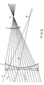
- Figure 1 is a schematic diagram of a doubly concave acoustic lens and associated spherical shell segment electroacoustic transducer, with a superposed ray diagram illustrating the focusing action of the lens, and
- Figure 2 is a cross sectional view of the transducer.
- The invention is concerned with a multiple beam transducer that uses a single aperture in the form of an acoustic lens which provides the required aperture-to-wavelength ratio. A ray diagram depicting the focusing action of an acoustic lens is shown in Figure 1. Parallel rays of an
incident plane wave 10, propagating in the water medium 11, impinge on theacoustic lens 12. To focus an incident plane wave, the lens is chosen doubly concave and constructed of a medium wherein the sound velocity is greater than the sound velocity in the water and the otheradjacent medium 13. The focusing action results from the beams being first bent away from the normal to the surface of the lower refractive index lens as it enters the lens, and then upon emergence from the lens, being bent towards the normal. Accordingly, incidentplane sound wave 10 is focused to apoint 14 by the lens thus constructed. Conversely, a point source at 14 illuminating the lens with a sound wave will cause the projection of a plane wave depicted by theparallel rays 10. Characteristic of a lens constructed in this fashion is a unique correspondence between the direction of incidence of a plane wave, and the associated focal point in the focal plane of the lens. Simply, collimated beams incident from different directions have different focal points. For example, the plane wave incident fromdirection 15 will be focused atpoint 16. Thus, a multiplicity of such focal points lie in the focal plane, each of which can define a different beam direction for reception or projection of sound waves. A multiplicity of small electroacoustic transducers placed at different focal points can then be used to transmit and receive sound beams such that the beam width is characterised by the lens diameter. - A major deterrent to the implementation of this arrangement is the inability of the small transducers to operate at significant power levels. The sound intensity (watts per unit area) in the
medium 13 in the vicinity of the transducer is intense because of the small transducer surface area, causing cavitation and disruption of the medium. In addition, the heat dissipation produced by transducer losses is confined to the small transducer surface, causing high temperatures to be generated if significant electrical power is supplied. In the present invention, larger transducers having significant surface area are employed, and are placed forward of the focal points. Anelectroacoustic transducer 17, is shaped in the form of a segment of a spherical shell, the radius of which is at the desired focal point. All rays impinging on 17 are in phase at the surface, since all surface elements are the same distance from the focal point by virtue of its spherical shape. All the acoustic energy received bylens 12 is thus available for conversion to electrical energy by the transducer. Conversely, when acting as a transmitter, the transducer radiates spherical waves as though thefocal point 14 were the source. A further advantage obtained by this arrangement is that small changes in the position of the focal point do not cause drastic changes in the performance, since all rays are still encompassed by the transducer with only small out of phase interference. With small transducer elements directly at the focal point, small changes in focal point location can cause large changes in the captured energy. A further advantage is realised in the depth of the transducer being reduced, since the distance in themedium 13 behind the lens need not extend to the focal plane. - A typical design embodying the present invention is shown in Figure 2. A
solid lens 18, of cross linked polystyrene, 8.57 cm (3.375 inches) in diameter, 0.47 cm (0.187 inches) centre thickness, with external radius of 33.78 cm (13.3 inches), and internal radius of 9.5 cm (3.74 inches) is in contact with water on its outer surface and bonded on its inner surface to a medium 19, of silicone rubber. The arrangement shown provides for three transmitting or receiving beams each 15 degrees off the len's central axis. The low sound speed in rubber produces a shortfocal length 20, of 14 cm (5.52 inches), thus further diminishing the assembly depth. Thesubtended angle 21 is 37 degrees. Three spherical shell segment piezoelectric crystals, (one of which is crystal 22) centred at focal points, (one of which is focal point 23) of outer radius 4 cm (1.587 inches), and of such thickness that they resonate at 400 kHz, are bonded to ametal support 24. Interposed between each crystal and the silicone rubber medium is first ametallic window 25, followed by an impedance matchingsection 26 of a synthetic plastics material such as an epoxy. Themetallic window 25 is an aluminium spherical shell segment with a thickness which is an integral multiple of a half wave length, in this case 0.79 cm (0.311 inches). Thewindow 25 provides both structural strength and heat transport for the crystals, and is essentially transparent at the operating frequency. The transparency, that is, the negligible effect upon the transmission of waves, follows from the standard sound transmission coefficient formula for waves traversing two boundaries (see, for example, Fundamentals of Acoustics, page 149 to 153, by Kinsler and Frey, Wiley, 1950). The impedance matchingsection 26 is also a spherical shell segment, with thickness equal to an odd multiple of a quarter wavelength, in this embodiment a quarter wavelength, 0.165cm (0.065 inches). The matching section provides favourable electrical characteristics when measured at the electrical terminals of the crystals by transforming the low acoustic impedance of the rubber to a higher value for presentation to the crystals. Essentially, two purposes are served by the matching section 26: it broadens bandwidth, and increases efficiency of the transducer (see The Effect of Backing and Matching on the Performance of Piezoelectric Ceramic Transducers, by George Kossoff, IEEE Transactions on Sonics and Ultrasonics, Volume SU-13, No. 1, March 1966).
Claims (12)
Applications Claiming Priority (2)
| Application Number | Priority Date | Filing Date | Title |
|---|---|---|---|
| US354973 | 1982-03-05 | ||
| US06/354,973 US4450542A (en) | 1982-03-05 | 1982-03-05 | Multiple beam lens transducer for sonar systems |
Publications (3)
| Publication Number | Publication Date |
|---|---|
| EP0088569A2 EP0088569A2 (en) | 1983-09-14 |
| EP0088569A3 EP0088569A3 (en) | 1985-03-13 |
| EP0088569B1 true EP0088569B1 (en) | 1990-04-18 |
Family
ID=23395693
Family Applications (1)
| Application Number | Title | Priority Date | Filing Date |
|---|---|---|---|
| EP83301041A Expired - Lifetime EP0088569B1 (en) | 1982-03-05 | 1983-02-28 | Multiple beam lens transducer for sonar systems |
Country Status (6)
| Country | Link |
|---|---|
| US (1) | US4450542A (en) |
| EP (1) | EP0088569B1 (en) |
| JP (1) | JPS58158571A (en) |
| DE (1) | DE3381480D1 (en) |
| ES (1) | ES520317A0 (en) |
| NO (1) | NO166468C (en) |
Families Citing this family (7)
| Publication number | Priority date | Publication date | Assignee | Title |
|---|---|---|---|---|
| JPS59120976A (en) * | 1982-12-27 | 1984-07-12 | スペリ−・コ−ポレイシヨン | Multi-beam lens converting device with collimating device for sonar device |
| DE3441563A1 (en) * | 1984-11-14 | 1985-05-30 | Michael Dipl.-Phys. 5600 Wuppertal Platte | Combined ultrasound transducer consisting of ceramic and highly polymerised piezoelectric materials |
| US5090432A (en) * | 1990-10-16 | 1992-02-25 | Verteq, Inc. | Single wafer megasonic semiconductor wafer processing system |
| FR2669248A1 (en) * | 1990-11-19 | 1992-05-22 | Ngeh Toong See | Device for supporting and protecting ultrasonic transducers, which can focus and transmit ultrasound |
| JP6604717B2 (en) * | 2014-09-30 | 2019-11-13 | キヤノン株式会社 | measuring device |
| US10184903B2 (en) | 2015-09-11 | 2019-01-22 | Samsung Display Co., Ltd. | Device for evaluating crystallinity and method of evaluating crystallinity |
| CN111112037A (en) * | 2020-01-20 | 2020-05-08 | 重庆医科大学 | Lens type multi-frequency focusing ultrasonic transducer, transduction system and method for determining axial length of acoustic focal region of lens type multi-frequency focusing ultrasonic transducer |
Citations (1)
| Publication number | Priority date | Publication date | Assignee | Title |
|---|---|---|---|---|
| US4001766A (en) * | 1975-02-26 | 1977-01-04 | Westinghouse Electric Corporation | Acoustic lens system |
Family Cites Families (11)
| Publication number | Priority date | Publication date | Assignee | Title |
|---|---|---|---|---|
| US2452068A (en) * | 1943-01-23 | 1948-10-26 | Submarine Signal Co | Sound pickup device |
| US2968302A (en) * | 1956-07-20 | 1961-01-17 | Univ Illinois | Multibeam focusing irradiator |
| US3800275A (en) * | 1960-09-02 | 1974-03-26 | Us Navy | Acoustic image conversion tube |
| JPS437677Y1 (en) * | 1965-01-02 | 1968-04-05 | ||
| US3687219A (en) * | 1969-06-09 | 1972-08-29 | Holotron Corp | Ultrasonic beam expander |
| FR2098517A5 (en) * | 1970-07-10 | 1972-03-10 | Thomson Csf | |
| US3663842A (en) * | 1970-09-14 | 1972-05-16 | North American Rockwell | Elastomeric graded acoustic impedance coupling device |
| US3776361A (en) * | 1972-04-06 | 1973-12-04 | Us Navy | Acoustic lens |
| US3866711A (en) * | 1973-06-04 | 1975-02-18 | Us Navy | Solid ultrasonic lens doublet |
| US3979565A (en) * | 1975-08-11 | 1976-09-07 | Westinghouse Electric Corporation | Metal enclosed transducer assembly |
| JPS6229957Y2 (en) * | 1980-03-26 | 1987-08-01 |
-
1982
- 1982-03-05 US US06/354,973 patent/US4450542A/en not_active Expired - Lifetime
-
1983
- 1983-01-12 JP JP58002366A patent/JPS58158571A/en active Granted
- 1983-02-28 EP EP83301041A patent/EP0088569B1/en not_active Expired - Lifetime
- 1983-02-28 DE DE8383301041T patent/DE3381480D1/en not_active Expired - Fee Related
- 1983-03-04 NO NO830767A patent/NO166468C/en unknown
- 1983-03-04 ES ES520317A patent/ES520317A0/en active Granted
Patent Citations (1)
| Publication number | Priority date | Publication date | Assignee | Title |
|---|---|---|---|---|
| US4001766A (en) * | 1975-02-26 | 1977-01-04 | Westinghouse Electric Corporation | Acoustic lens system |
Also Published As
| Publication number | Publication date |
|---|---|
| DE3381480D1 (en) | 1990-05-23 |
| ES8403688A1 (en) | 1984-03-16 |
| NO166468C (en) | 1991-07-24 |
| US4450542A (en) | 1984-05-22 |
| EP0088569A2 (en) | 1983-09-14 |
| JPH0344268B2 (en) | 1991-07-05 |
| NO830767L (en) | 1983-09-06 |
| ES520317A0 (en) | 1984-03-16 |
| EP0088569A3 (en) | 1985-03-13 |
| JPS58158571A (en) | 1983-09-20 |
| NO166468B (en) | 1991-04-15 |
Similar Documents
| Publication | Publication Date | Title |
|---|---|---|
| US3243768A (en) | Integral directional electroacoustical transducer for simultaneous transmission and reception of sound | |
| US3414903A (en) | Antenna system with dielectric horn structure interposed between the source and lens | |
| US4836328A (en) | Omnidirectional acoustic transducer | |
| US2448365A (en) | Projector and receiver of supersonic frequencies | |
| EP0088569B1 (en) | Multiple beam lens transducer for sonar systems | |
| US4328569A (en) | Array shading for a broadband constant directivity transducer | |
| US3872421A (en) | Standing wave acoustic parametric source | |
| US4844198A (en) | Plane wave focusing lens | |
| US3021504A (en) | Apparatus for controlling the effective compressibility of a liquid | |
| CA1136262A (en) | Electro-acoustic transducer with horn and reflector | |
| US4025805A (en) | Conical transducer and reflector apparatus | |
| US2753543A (en) | Transducers | |
| US2761117A (en) | Directional transducer | |
| US4484317A (en) | Multibeam lens/filter combination for sonar sensor | |
| US4551826A (en) | Multiple beam lens transducer with collimator for sonar systems | |
| US4320474A (en) | Saturation limited parametric sonar source | |
| JP7265977B2 (en) | ultrasonic generator | |
| EP0112688B1 (en) | Multiple beam lens transducer with collimator for sonar systems | |
| US4445207A (en) | Frequency independent acoustic antenna | |
| US3427625A (en) | Focussing reflector with dimpled surface to scatter infra-red radiation | |
| US4480324A (en) | Constant beamwidth frequency independent acoustic antenna | |
| US4187556A (en) | Electro-acoustic transducer with line focus | |
| US3483614A (en) | Method for making dimpled honeycomb sandwich | |
| US4982386A (en) | Underwater acoustic waveguide transducer for deep ocean depths | |
| US3483504A (en) | Transducer |
Legal Events
| Date | Code | Title | Description |
|---|---|---|---|
| PUAI | Public reference made under article 153(3) epc to a published international application that has entered the european phase |
Free format text: ORIGINAL CODE: 0009012 |
|
| AK | Designated contracting states |
Designated state(s): DE FR GB IT NL SE |
|
| PUAL | Search report despatched |
Free format text: ORIGINAL CODE: 0009013 |
|
| AK | Designated contracting states |
Designated state(s): DE FR GB IT NL SE |
|
| 17P | Request for examination filed |
Effective date: 19850731 |
|
| 17Q | First examination report despatched |
Effective date: 19861223 |
|
| RAP1 | Party data changed (applicant data changed or rights of an application transferred) |
Owner name: SPERRY MARINE INC. |
|
| ITF | It: translation for a ep patent filed |
Owner name: FIAMMENGHI - DOMENIGHETTI |
|
| GRAA | (expected) grant |
Free format text: ORIGINAL CODE: 0009210 |
|
| AK | Designated contracting states |
Kind code of ref document: B1 Designated state(s): DE FR GB IT NL SE |
|
| ET | Fr: translation filed | ||
| REF | Corresponds to: |
Ref document number: 3381480 Country of ref document: DE Date of ref document: 19900523 |
|
| PLBE | No opposition filed within time limit |
Free format text: ORIGINAL CODE: 0009261 |
|
| STAA | Information on the status of an ep patent application or granted ep patent |
Free format text: STATUS: NO OPPOSITION FILED WITHIN TIME LIMIT |
|
| 26N | No opposition filed | ||
| ITTA | It: last paid annual fee | ||
| PGFP | Annual fee paid to national office [announced via postgrant information from national office to epo] |
Ref country code: FR Payment date: 19940211 Year of fee payment: 12 |
|
| EAL | Se: european patent in force in sweden |
Ref document number: 83301041.6 |
|
| PG25 | Lapsed in a contracting state [announced via postgrant information from national office to epo] |
Ref country code: FR Effective date: 19951031 |
|
| REG | Reference to a national code |
Ref country code: FR Ref legal event code: ST |
|
| PGFP | Annual fee paid to national office [announced via postgrant information from national office to epo] |
Ref country code: DE Payment date: 19980227 Year of fee payment: 16 |
|
| PG25 | Lapsed in a contracting state [announced via postgrant information from national office to epo] |
Ref country code: DE Free format text: LAPSE BECAUSE OF NON-PAYMENT OF DUE FEES Effective date: 19991201 |
|
| PGFP | Annual fee paid to national office [announced via postgrant information from national office to epo] |
Ref country code: SE Payment date: 19991223 Year of fee payment: 18 |
|
| PGFP | Annual fee paid to national office [announced via postgrant information from national office to epo] |
Ref country code: NL Payment date: 20000125 Year of fee payment: 18 |
|
| PG25 | Lapsed in a contracting state [announced via postgrant information from national office to epo] |
Ref country code: SE Free format text: LAPSE BECAUSE OF NON-PAYMENT OF DUE FEES Effective date: 20010301 |
|
| PG25 | Lapsed in a contracting state [announced via postgrant information from national office to epo] |
Ref country code: NL Free format text: LAPSE BECAUSE OF NON-PAYMENT OF DUE FEES Effective date: 20010901 |
|
| NLV4 | Nl: lapsed or anulled due to non-payment of the annual fee |
Effective date: 20010901 |
|
| EUG | Se: european patent has lapsed |
Ref document number: 83301041.6 |
|
| REG | Reference to a national code |
Ref country code: GB Ref legal event code: IF02 |
|
| PGFP | Annual fee paid to national office [announced via postgrant information from national office to epo] |
Ref country code: GB Payment date: 20020129 Year of fee payment: 20 |
|
| PG25 | Lapsed in a contracting state [announced via postgrant information from national office to epo] |
Ref country code: GB Free format text: LAPSE BECAUSE OF EXPIRATION OF PROTECTION Effective date: 20030227 |
|
| REG | Reference to a national code |
Ref country code: GB Ref legal event code: PE20 Effective date: 20030227 |