EP0088458A2 - Process for the separation of a liquid mixture - Google Patents
Process for the separation of a liquid mixture Download PDFInfo
- Publication number
- EP0088458A2 EP0088458A2 EP83200204A EP83200204A EP0088458A2 EP 0088458 A2 EP0088458 A2 EP 0088458A2 EP 83200204 A EP83200204 A EP 83200204A EP 83200204 A EP83200204 A EP 83200204A EP 0088458 A2 EP0088458 A2 EP 0088458A2
- Authority
- EP
- European Patent Office
- Prior art keywords
- membrane
- extracting agent
- component
- stream
- mixture
- Prior art date
- Legal status (The legal status is an assumption and is not a legal conclusion. Google has not performed a legal analysis and makes no representation as to the accuracy of the status listed.)
- Granted
Links
Images


Classifications
-
- B—PERFORMING OPERATIONS; TRANSPORTING
- B01—PHYSICAL OR CHEMICAL PROCESSES OR APPARATUS IN GENERAL
- B01D—SEPARATION
- B01D11/00—Solvent extraction
- B01D11/04—Solvent extraction of solutions which are liquid
-
- C—CHEMISTRY; METALLURGY
- C10—PETROLEUM, GAS OR COKE INDUSTRIES; TECHNICAL GASES CONTAINING CARBON MONOXIDE; FUELS; LUBRICANTS; PEAT
- C10G—CRACKING HYDROCARBON OILS; PRODUCTION OF LIQUID HYDROCARBON MIXTURES, e.g. BY DESTRUCTIVE HYDROGENATION, OLIGOMERISATION, POLYMERISATION; RECOVERY OF HYDROCARBON OILS FROM OIL-SHALE, OIL-SAND, OR GASES; REFINING MIXTURES MAINLY CONSISTING OF HYDROCARBONS; REFORMING OF NAPHTHA; MINERAL WAXES
- C10G73/00—Recovery or refining of mineral waxes, e.g. montan wax
- C10G73/02—Recovery of petroleum waxes from hydrocarbon oils; Dewaxing of hydrocarbon oils
- C10G73/06—Recovery of petroleum waxes from hydrocarbon oils; Dewaxing of hydrocarbon oils with the use of solvents
-
- B—PERFORMING OPERATIONS; TRANSPORTING
- B01—PHYSICAL OR CHEMICAL PROCESSES OR APPARATUS IN GENERAL
- B01D—SEPARATION
- B01D11/00—Solvent extraction
- B01D11/04—Solvent extraction of solutions which are liquid
- B01D11/0415—Solvent extraction of solutions which are liquid in combination with membranes
-
- B—PERFORMING OPERATIONS; TRANSPORTING
- B01—PHYSICAL OR CHEMICAL PROCESSES OR APPARATUS IN GENERAL
- B01D—SEPARATION
- B01D61/00—Processes of separation using semi-permeable membranes, e.g. dialysis, osmosis or ultrafiltration; Apparatus, accessories or auxiliary operations specially adapted therefor
- B01D61/24—Dialysis ; Membrane extraction
- B01D61/246—Membrane extraction
-
- C—CHEMISTRY; METALLURGY
- C10—PETROLEUM, GAS OR COKE INDUSTRIES; TECHNICAL GASES CONTAINING CARBON MONOXIDE; FUELS; LUBRICANTS; PEAT
- C10G—CRACKING HYDROCARBON OILS; PRODUCTION OF LIQUID HYDROCARBON MIXTURES, e.g. BY DESTRUCTIVE HYDROGENATION, OLIGOMERISATION, POLYMERISATION; RECOVERY OF HYDROCARBON OILS FROM OIL-SHALE, OIL-SAND, OR GASES; REFINING MIXTURES MAINLY CONSISTING OF HYDROCARBONS; REFORMING OF NAPHTHA; MINERAL WAXES
- C10G21/00—Refining of hydrocarbon oils, in the absence of hydrogen, by extraction with selective solvents
- C10G21/28—Recovery of used solvent
-
- C—CHEMISTRY; METALLURGY
- C10—PETROLEUM, GAS OR COKE INDUSTRIES; TECHNICAL GASES CONTAINING CARBON MONOXIDE; FUELS; LUBRICANTS; PEAT
- C10G—CRACKING HYDROCARBON OILS; PRODUCTION OF LIQUID HYDROCARBON MIXTURES, e.g. BY DESTRUCTIVE HYDROGENATION, OLIGOMERISATION, POLYMERISATION; RECOVERY OF HYDROCARBON OILS FROM OIL-SHALE, OIL-SAND, OR GASES; REFINING MIXTURES MAINLY CONSISTING OF HYDROCARBONS; REFORMING OF NAPHTHA; MINERAL WAXES
- C10G31/00—Refining of hydrocarbon oils, in the absence of hydrogen, by methods not otherwise provided for
- C10G31/11—Refining of hydrocarbon oils, in the absence of hydrogen, by methods not otherwise provided for by dialysis
Definitions
- the invention relates to a process for the separation of a liquid mixture of two components A and B by contacting the mixture with an extracting agent in which component B is soluble and component A is (as good as) insoluble, subsequently separating component A from the extracting agent which contains the dissolved component B and finally separating component B from the extracting agent.
- Component A is called the raffinate and component B is called the extract.
- component B is called the extract.
- the extracting agent is sometimes referred to as solvent, in particular when a single solid and a single liquid component are involved.
- the mixture may comprise more than two materials, but according to the present process it is divided into two components.
- the invention therefore provides a process for the separation of a liquid mixture of two components A and B by contacting the mixture with an extracting agent in which component B is soluble and component A is (as good as) insoluble, subsequently separating component A from the extracting agent which contains the dissolved component B and finally separating component B from the extracting agent, characterized in that a stream of the mixture is passed along one side of a membrane along both sides of which a flow can be maintained, while a previously formed stream of the extracting agent containing the dissolved component B is passed along the other side of the membrane, with the membrane being substantially permeable to the extracting agent, but non-permeable to component A, after which the mixture of components A and B which has taken up the extracting agent at least partly is passed to a separator in which component A is separated from the extracting agent containing the dissolved component B, thus forming the stream that is passed along the other side of the membrane.
- membranes In itself the use of membranes is known - for instance in dialysis processes - but in the known membrane processes some component or impurity or other migrates through the membrane, whereas in the present invention it is the solvent that migrates through the membrane. In the case of a membrane along both sides of which a flow can be maintained, a liquid to be purified may be present on one side and a sweep liquid on the other side.
- the known membrane processes have been put to use almost exclusively in inorganic chemistry, for instance in the desalination of seawater or in kidney dialysis, but the invention is particularly - though not exclusively - suitable for use in organic processes, in particular for the extraction processes used in the petroleum industry for separating hydrocarbon mixtures.
- the invention therefore relates in particular to a process for the extraction of a hydrocarbon mixture by contacting it with an extracting agent according to the invention generally described hereinbefore.
- Processes 11 and 12 of Table A relate to liquid-solid separations, the other processes are liquid-liquid extractions.
- Asphaltenes (process 1) may at times be very tough, yet from a physical point of view they form a liquid.
- the measure taken according to the invention has the advantage that the extracting agent, which used to be separated from component B in a cumbersome and costly manner (for instance through distillation, crystallization or stripping) and subsequently reintroduced into the mixture to be separated, is now transferred in a simple way from component B which has already been separated to the mixture that has yet to be treated. Separation and reintroduction can be carried out at the same temperature and pressure, which means an important saving in energy cost.
- the separator in which component A is separated from the stream of extracting agent and component B is not quite perfect, viz. if, upon leaving the separator, component A is still mixed with a (small) quantity of extracting agent, then a final separation of extracting agent and component A should still be carried out.
- a membrane along both sides of which a flow can be maintained may be used, if desired, and thus the extracting agent may be transferred at least partly to the mixture to be separated.
- the membrane to be used should be substantially impermeable to component B.
- the saving achieved will be less here.
- the membrane is substantially permeable to the extracting agent and impermeable to component A.
- the membrane is also substantially permeable to component B, which is advantageous when the concentration of component B is higher in the mixture of components A and B than in the stream containing the extracting agent.
- the existing concentration gradient allows component B to diffuse from one side of the membrane to the other, which is just what is aimed at, viz. separation of components A and B.
- the concentration of component B in the stream containing the extracting agent is higher and the membrane is permeable to component B, care should be taken that this concentration is reduced, for instance by the addition of extracting agent.
- the latter in other words means a higher "solvent ratio".
- An additional advantage is that the mixture of components A and B is prediluted prior to being passed along the membrane. Particularly in the case of highly viscous liquids, such as residual oils, this is an advantage since this improves their pumpability and/or offers the opportunity of lowering the temperature.
- the stream is further treated as described hereinbefore on the subject of a single membrane.
- the stream of components A and B is supplied to the separator and the other stream, now consisting almost entirely of pure component B, may optionally be subjected to a final purification treatment (e.g. stripping).
- the number of membranes will be dependent on the type of process, the supply rates per unit time and the size of the membranes, but preferably the number will be 2 to 20, in particular 4 to 10.
- the membrane material may be chosen from the materials known for the purpose, such as polyethylene, polypropylene, cellulose acetate, butyl rubber, methyl rubber, silicon rubber, polystyrene, polytetrafluoro-ethylene and other polymeric materials.
- the material should be insoluble both in components A and B and in the extracting agent, and it should also be totally or practically impermeable to component A and, on the other hand, permeable to the extracting agent. Fouling of the membrane by solid or viscous elements of the mixture of components A and B need not be feared, because it has been ascertained that the membrane remains clean in actual practice. It is assumed that the membrane is continuously rinsed by diffusing extracting agent.
- the configuration in which the membrane material is used may be one of the membrane units along both sides of which a flow can be maintained which in themselves are known, such as the flat sheet or the tubular membrane unit.
- Such configurations are not very economical of space and therefore do no achieve a high packing density (m 2 membrane/m 3 apparatus).
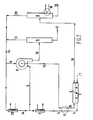
- Figure I represents a general flow diagram of the process according to the invention and Figures 2 and 3 are elaborations thereof representing flow diagrams of a solvent dewaxing unit and a deasphaltenizing unit, respectively.
- Figure 1 very schematically indicates the way in which a mixture to be separated (A + B) is fed to a membrane unit (M), where extracting agent (E) joins the stream of the mixture to be separated. The resulting stream is then fed to a separator (S), where.component A is separated off. The remainder, viz. component B and the extracting agent, is recirculated to the membrane unit (M) in order to transfer the extracting agent to a fresh supply of mixture to be separated. If the membrane is permeable to component B and if the concentration of component B is higher in mixture (A + B) than in mixture (E + B), there will also be migration of component B along the membrane in the direction opposite to that of the extracting agent (dashed line B 1 ).
- FIG 2 shows a flow diagram of a unit for dewaxing with the aid of a solvent, which, according to the invention, includes a membrane unit.
- the feed for instance a waxy furfural raffinate
- solvent (extracting agent) 3 joins the feed.
- solvent a mixture of aromatics (benzene, toluene, etc.) and methyl ethyl ketone may be used.
- conduits 4 and 5 the feed and the solvent are transferred further via a heat exchanger 6 and a cooler 7,-to a vacuum rotary drum filter 8.
- unit 17 will generally comprise two flashing columns - one operated at low pressure and temperature and one at higher pressure and temperature - followed by a steam stripper, in conjunction with distillation columns for the removal of water from the solvent and a number of pumps, burners and reflux pipes, which together have been drawn as unit 17.
- the required heat is supplied by a heat exchanger 18.
- dewaxed oil 19 is in the end separated from the solvent which, through conduits 20 and 14 and via a cooler 21, is reintroduced into the system, that is to say, the feedstock present in line 5.
- FIG. 3 is a drawing of a flow diagram of a deasphaltenizing unit.
- Figure 3 is a drawing of a flow diagram of a deasphaltenizing unit.
- most of the ancillary equipment known in itself and not essential to the invention has been left out of this diagram as well.
- the feedstock is fed to a mixing vessel 32, where the feed is prediluted with a stream of feed already diluted with extracting agent leaving a conduit 33.
- Mixing vessel 32 also acts as a buffer vessel so as to eliminate changes in the supply. From mixing vessel 32 there is a continuous discharge, through conduit 34, of a stream part-of which is fed, through a conduit 101 to a membrane unit 100 and the remaining part through conduits 106 and 201 to a membrane unit 200.
- a certain amount of extracting agent diffuses from a stream of deasphaltenized oil and solvent, supplied via conduits 103 and 203, respectively, through the membrane into the stream of the prediluted feed which has been supplied through conduits 101 and 201, respectively and is discharged through conduits 104 and 204, respectively.
- Conduit 104 is connected with conduit 33 which leads to the mixing vessel and conduit 204 recirculates part of the diluted feed to membrane unit 200 through a conduit 205 and conduit 201, while the rest of the diluted feed is fed to a next membrane unit through a conduit 206.
- the stream of deasphaltenized oil with extracting agent which has released part of the extracting agent in membrane units 100 and 200, respectively, is discharged through conduits 107 and 207, respectively. Part of it is recirculated to the original membrane unit through conduits 108 and 103 and 208 and 203, respectively, while the remainder is discharged through conduits 109 and 209, respectively.
- Conduit 209 is connected with the preceding membrane unit by conduit 103, while conduit 109 is connected with a stripper unit 35, in which the last residues of extracting agent 36 are removed from the stream of deasphaltenized oil 37 with the aid of steam.
- the number of membrane units may vary, but in the embodiment described here the number is 7.
- conduit 601 corresponds with conduits 201 and 101.
- the part of the stream of feed with extracting agent which is discharged through conduit 706 is fed to what is called a rotating-disc-contactor 38, where this stream is split up into an asphaltenes fraction which is discharged through a conduit 39 and a fraction of deasphaltenized oil with extracting agent which is run through a conduit 40 into conduit 703, with the object of removing the solvent in membrane unit 700 (and subsequently in units 600, 500, etc.).
- the asphaltenes fraction is freed from remaining extracting agent, if any, in a stripper 41, so that in the end a quantity of asphaltenes can be discharged through conduit 42 and a quantity of extracting agent through conduit 43. Both the streams of conduits 43 and 46 are recirculated through a conduit 44 to the rotating-disc-contactor 38 so as to enable all the extracting agent to be mixed with the feed.
- stream 16 contains much less solvent than it does in the embodiment in which no membrane is used and that, consequently, less solvent need be flashed and stripped in processing unit 17. Therefore, less heat is required for the removal of the solvent from the dewaxed oil (8708 MJ/h instead of 21855 MJ/h).
Landscapes
- Chemical & Material Sciences (AREA)
- Chemical Kinetics & Catalysis (AREA)
- Oil, Petroleum & Natural Gas (AREA)
- Engineering & Computer Science (AREA)
- General Chemical & Material Sciences (AREA)
- Organic Chemistry (AREA)
- Health & Medical Sciences (AREA)
- Urology & Nephrology (AREA)
- Water Supply & Treatment (AREA)
- Separation Using Semi-Permeable Membranes (AREA)
- Production Of Liquid Hydrocarbon Mixture For Refining Petroleum (AREA)
- Extraction Or Liquid Replacement (AREA)
Abstract
Description
- The invention relates to a process for the separation of a liquid mixture of two components A and B by contacting the mixture with an extracting agent in which component B is soluble and component A is (as good as) insoluble, subsequently separating component A from the extracting agent which contains the dissolved component B and finally separating component B from the extracting agent.
- This is a well-known process, particularly for the separation of a mixture of two liquids, and is usually called extraction. Component A is called the raffinate and component B is called the extract. However, mixtures of a liquid and a solid material may also be separated in this way. The extracting agent is sometimes referred to as solvent, in particular when a single solid and a single liquid component are involved. Naturally, the mixture may comprise more than two materials, but according to the present process it is divided into two components.
- This process has a drawback in the problems generally posed by the working-up of a certain amount of extracting agent which extracting agent may be recirculated time and again for re-use after component B has been separated therefrom; but it is this very separation that takes so much energy, for instance in the form of heat, which has to be supplied to a distillation unit.
- It is the object of the invention to reduce the cost of this separation. This is achieved according to the invention by the use of a membrane along which are passed on one side the flow of the mixture of components A and B and on the other side the flow of the extracting agent containing the dissolved component B, with the membrane selectively allowing the passage of the extracting agent. In this way the extracting agent is separated at least partly from component B.
- The invention therefore provides a process for the separation of a liquid mixture of two components A and B by contacting the mixture with an extracting agent in which component B is soluble and component A is (as good as) insoluble, subsequently separating component A from the extracting agent which contains the dissolved component B and finally separating component B from the extracting agent, characterized in that a stream of the mixture is passed along one side of a membrane along both sides of which a flow can be maintained, while a previously formed stream of the extracting agent containing the dissolved component B is passed along the other side of the membrane, with the membrane being substantially permeable to the extracting agent, but non-permeable to component A, after which the mixture of components A and B which has taken up the extracting agent at least partly is passed to a separator in which component A is separated from the extracting agent containing the dissolved component B, thus forming the stream that is passed along the other side of the membrane.
- In itself the use of membranes is known - for instance in dialysis processes - but in the known membrane processes some component or impurity or other migrates through the membrane, whereas in the present invention it is the solvent that migrates through the membrane. In the case of a membrane along both sides of which a flow can be maintained, a liquid to be purified may be present on one side and a sweep liquid on the other side. In addition, the known membrane processes have been put to use almost exclusively in inorganic chemistry, for instance in the desalination of seawater or in kidney dialysis, but the invention is particularly - though not exclusively - suitable for use in organic processes, in particular for the extraction processes used in the petroleum industry for separating hydrocarbon mixtures.
- The invention therefore relates in particular to a process for the extraction of a hydrocarbon mixture by contacting it with an extracting agent according to the invention generally described hereinbefore.
- Examples of such hydrocarbon extractions are given in Table A hereinafter.


-
Processes - The measure taken according to the invention has the advantage that the extracting agent, which used to be separated from component B in a cumbersome and costly manner (for instance through distillation, crystallization or stripping) and subsequently reintroduced into the mixture to be separated, is now transferred in a simple way from component B which has already been separated to the mixture that has yet to be treated. Separation and reintroduction can be carried out at the same temperature and pressure, which means an important saving in energy cost.
- Depending on the conditions used a larger or a smaller portion of the total quantity of extracting agent will be transferred through the membrane. Therefore, there will be certain cases in which one more final separation will be carried out, but this separation will always be carried out on a smaller scale and therefore be less expensive than a process which is not preceded by the removal of extracting agent through a membrane.
- If the separator in which component A is separated from the stream of extracting agent and component B is not quite perfect, viz. if, upon leaving the separator, component A is still mixed with a (small) quantity of extracting agent, then a final separation of extracting agent and component A should still be carried out. In the processes used up till now that separation was usually carried out by distillation, crystallization or stripping, but also in these processes a membrane along both sides of which a flow can be maintained may be used, if desired, and thus the extracting agent may be transferred at least partly to the mixture to be separated. In this case the membrane to be used should be substantially impermeable to component B. However, in view of the relatively small quantities of extracting agent which in actual practice are generally yielded by component A, the saving achieved will be less here.
- The membrane is substantially permeable to the extracting agent and impermeable to component A. In a certain embodiment of the invention the membrane is also substantially permeable to component B, which is advantageous when the concentration of component B is higher in the mixture of components A and B than in the stream containing the extracting agent. In that case the existing concentration gradient allows component B to diffuse from one side of the membrane to the other, which is just what is aimed at, viz. separation of components A and B. But if the concentration of component B in the stream containing the extracting agent is higher and the membrane is permeable to component B, care should be taken that this concentration is reduced, for instance by the addition of extracting agent. The latter in other words means a higher "solvent ratio".
- It is known that in membrane processes such as those according to the invention concentration polarization may arise. As a consequence, in the present process, there where the extracting agent diffuses from the "other side" to the "one side" of the membrane, a layer almost exclusively consisting of component B may form along the "other side" of the membrane and, similarly, a layer almost exclusively consisting of extracting agent may form along the "one side" of the membrane. Naturally, this local reversal of the concentration gradient has a restraining influence on the diffusion of the extracting agent. In order to prevent such concentration polarization, the streams are preferably pumped rapidly along both sides of the membrane and - in order not to use too large a membrane surface - the streams are recirculated. Thus, as homogeneous a mixture as possible will constantly be present both on one side and on the other side of the membrane. Pumping rates will preferably be so high that a molecule which can diffuse through the membrane will pass along the membrane some 10 to 30 times before diffusing through it.
- Firstly this means that preferably part of the mixture of components A and B which has taken up the extracting agent at least partly, is reintroduced into the stream of the mixture of components A and B (upstream of the membrane) and is thus passed along the "one side" of the membrane again. An additional advantage is that the mixture of components A and B is prediluted prior to being passed along the membrane. Particularly in the case of highly viscous liquids, such as residual oils, this is an advantage since this improves their pumpability and/or offers the opportunity of lowering the temperature.
- Secondly, this means that preferably part of the stream of the extracting agent containing the dissolved component B, which is passed along the "other side" of the membrane is reintroduced into the stream of the extracting agent containing the dissolved component B, and is thus passed along the "other side" of the membrane again.
- Although in a number of cases a single membrane will be sufficient, there are many cases in which - in view of the imperfections of the commercially available units - the use of more than one membrane will be preferred, either for achieving a higher capacity (parallel arrangement), or deeper extraction (series arrangement). In the latter embodiment a number of membranes are arranged in series, the stream of components A and B which has been passed along the "one side" of any of the membranes subsequently being passed along the "one side" of the following membrane - if present - and, similarly, the stream of the extracting agent containing the dissolved component B, which has been passed along the "other side" of any of the membranes subsequently being passed along the "other side" of the preceding membrane - if present. Obviously, if no following or preceding membrane is available, the stream is further treated as described hereinbefore on the subject of a single membrane. In other words, then the stream of components A and B is supplied to the separator and the other stream, now consisting almost entirely of pure component B, may optionally be subjected to a final purification treatment (e.g. stripping).
- When more than one membrane is used, the number of membranes will be dependent on the type of process, the supply rates per unit time and the size of the membranes, but preferably the number will be 2 to 20, in particular 4 to 10.
- The membrane material may be chosen from the materials known for the purpose, such as polyethylene, polypropylene, cellulose acetate, butyl rubber, methyl rubber, silicon rubber, polystyrene, polytetrafluoro-ethylene and other polymeric materials. The material should be insoluble both in components A and B and in the extracting agent, and it should also be totally or practically impermeable to component A and, on the other hand, permeable to the extracting agent. Fouling of the membrane by solid or viscous elements of the mixture of components A and B need not be feared, because it has been ascertained that the membrane remains clean in actual practice. It is assumed that the membrane is continuously rinsed by diffusing extracting agent.
- The configuration in which the membrane material is used may be one of the membrane units along both sides of which a flow can be maintained which in themselves are known, such as the flat sheet or the tubular membrane unit. However, such configurations are not very economical of space and therefore do no achieve a high packing density (m2 membrane/m 3 apparatus).
- Preference is given to the use of the spirally wound membrane which has been described in the Applicant's Netherlands Patent "Application No. 8200880 of even date. The latter membrane combines the advantages - such as pressure resistance, low initial expense and high packing density - of the well-known spirally wound membranes along one side of which a flow can be maintained with the possibility of maintaining a flow on both sides.
- The invention will now be illustrated in more detail with the aid of the figures. Figure I represents a general flow diagram of the process according to the invention and Figures 2 and 3 are elaborations thereof representing flow diagrams of a solvent dewaxing unit and a deasphaltenizing unit, respectively.
- Figure 1 very schematically indicates the way in which a mixture to be separated (A + B) is fed to a membrane unit (M), where extracting agent (E) joins the stream of the mixture to be separated. The resulting stream is then fed to a separator (S), where.component A is separated off. The remainder, viz. component B and the extracting agent, is recirculated to the membrane unit (M) in order to transfer the extracting agent to a fresh supply of mixture to be separated. If the membrane is permeable to component B and if the concentration of component B is higher in mixture (A + B) than in mixture (E + B), there will also be migration of component B along the membrane in the direction opposite to that of the extracting agent (dashed line B1).
- Disregarding many details Figure 2 shows a flow diagram of a unit for dewaxing with the aid of a solvent, which, according to the invention, includes a membrane unit. The feed, for instance a waxy furfural raffinate, is supplied through line 1 to a
membrane unit 2, where solvent (extracting agent) 3 joins the feed. As solvent a mixture of aromatics (benzene, toluene, etc.) and methyl ethyl ketone may be used. Throughconduits heat exchanger 6 and a cooler 7,-to a vacuumrotary drum filter 8. In cooler 7 the feed and the solvent are cooled down to a temperature of about - 20°C in order to allow the paraffins present therein to crystallize. The paraffin crystals are washed on the drum ofdrum filter 8 using a thin stream of solvent 9 and subsequently scraped off and, together with a small quantity of solvent still present, carried off throughconduit 10 to a wax-processingunit 11, where what is called "slack wax" 12 is separated from the solvent, which, throughconduit 13, is fed to arecirculation line 14. The filtrate from the vacuumrotary drum filter 8, which consists of dewaxed oil and solvent, is passed through aconduit 15 viaheat exchanger 6 and fed tomembrane unit 2. Both inheat exchanger 6 and inmembrane unit 2 the feedstock is pre-cooled to some extent by its indirect contact with the cold filtrate. After a considerable part of the solvent has diffused through the membrane (stream 3), the dewaxed oil, together with the remainder of the solvent, is fed throughconduit 16 to a unit 17 for the processing of dewaxed oil. In reality unit 17 will generally comprise two flashing columns - one operated at low pressure and temperature and one at higher pressure and temperature - followed by a steam stripper, in conjunction with distillation columns for the removal of water from the solvent and a number of pumps, burners and reflux pipes, which together have been drawn as unit 17. The required heat is supplied by aheat exchanger 18. Here dewaxedoil 19 is in the end separated from the solvent which, throughconduits line 5. - Figure 3 is a drawing of a flow diagram of a deasphaltenizing unit. For the sake of simplicity, most of the ancillary equipment known in itself and not essential to the invention has been left out of this diagram as well.
- Through a
conduit 31 the feedstock, usually a vacuum residue, is fed to a mixingvessel 32, where the feed is prediluted with a stream of feed already diluted with extracting agent leaving aconduit 33. Mixingvessel 32 also acts as a buffer vessel so as to eliminate changes in the supply. From mixingvessel 32 there is a continuous discharge, throughconduit 34, of a stream part-of which is fed, through aconduit 101 to amembrane unit 100 and the remaining part throughconduits membrane unit 200. In these membrane units a certain amount of extracting agent, represented asstreams conduits conduits conduits Conduit 104 is connected withconduit 33 which leads to the mixing vessel andconduit 204 recirculates part of the diluted feed tomembrane unit 200 through aconduit 205 andconduit 201, while the rest of the diluted feed is fed to a next membrane unit through aconduit 206. The stream of deasphaltenized oil with extracting agent, which has released part of the extracting agent inmembrane units conduits conduits conduits 109 and 209, respectively. Conduit 209 is connected with the preceding membrane unit byconduit 103, whileconduit 109 is connected with astripper unit 35, in which the last residues of extractingagent 36 are removed from the stream ofdeasphaltenized oil 37 with the aid of steam. - The number of membrane units may vary, but in the embodiment described here the number is 7. For convenience units 300, 400 and 500 have been left out of the figure: only
units instance conduit 601 corresponds withconduits conduit 706 is fed to what is called a rotating-disc-contactor 38, where this stream is split up into an asphaltenes fraction which is discharged through aconduit 39 and a fraction of deasphaltenized oil with extracting agent which is run through aconduit 40 intoconduit 703, with the object of removing the solvent in membrane unit 700 (and subsequently inunits 600, 500, etc.). The asphaltenes fraction is freed from remaining extracting agent, if any, in astripper 41, so that in the end a quantity of asphaltenes can be discharged throughconduit 42 and a quantity of extracting agent throughconduit 43. Both the streams ofconduits 43 and 46 are recirculated through aconduit 44 to the rotating-disc-contactor 38 so as to enable all the extracting agent to be mixed with the feed. - The generation of steam and the subsequent separation of steam and extracting agent (e.g. propane) in stripping
unit 35 will require a certain amount of energy which will be greater in proportion as the fraction of extracting agent in the deasphaltenized oil is larger. According to the invention this fraction is small, since as much extracting agent as possible is transferred to the fresh feed viamembrane units streams streams membranes - Although the transfer of extracting agent drawn in this figure is a countercurrent one, this_transfer may naturally also take place co-currently.
- For further elucidation of the process according to the invention the results will now be given of an experiment in a dewaxing unit as described and drawn in Figure 2. Using a polypropylene-polyethylene copolymer membrane of 1µm in thickness, in the spiralled configuration described hereinbefore, almost 74% of the solvent (50 %v methyl ethyl ketone, 50 %v toluene) present in
stream 15 is transferred from there tostream 4. Table B gives a summary of the effect this has on the processing of the dewaxed oil. All the quantities given are expressed in tons per day (tpd).
- It is clear that according to the
invention stream 16 contains much less solvent than it does in the embodiment in which no membrane is used and that, consequently, less solvent need be flashed and stripped in processing unit 17. Therefore, less heat is required for the removal of the solvent from the dewaxed oil (8708 MJ/h instead of 21855 MJ/h).
Claims (7)
Applications Claiming Priority (2)
| Application Number | Priority Date | Filing Date | Title |
|---|---|---|---|
| NL8200881A NL193983C (en) | 1982-03-04 | 1982-03-04 | Method for separating a liquid mixture. |
| NL8200881 | 1982-03-04 |
Publications (3)
| Publication Number | Publication Date |
|---|---|
| EP0088458A2 true EP0088458A2 (en) | 1983-09-14 |
| EP0088458A3 EP0088458A3 (en) | 1984-03-07 |
| EP0088458B1 EP0088458B1 (en) | 1986-12-03 |
Family
ID=19839367
Family Applications (1)
| Application Number | Title | Priority Date | Filing Date |
|---|---|---|---|
| EP83200204A Expired EP0088458B1 (en) | 1982-03-04 | 1983-02-08 | Process for the separation of a liquid mixture |
Country Status (16)
| Country | Link |
|---|---|
| US (1) | US4670151A (en) |
| EP (1) | EP0088458B1 (en) |
| JP (1) | JPS58159804A (en) |
| KR (1) | KR900008728B1 (en) |
| AR (1) | AR241868A1 (en) |
| AU (1) | AU559866B2 (en) |
| BR (1) | BR8301003A (en) |
| CA (1) | CA1201660A (en) |
| DE (1) | DE3368013D1 (en) |
| GB (1) | GB2116071B (en) |
| IN (1) | IN158141B (en) |
| MY (1) | MY8700269A (en) |
| NL (1) | NL193983C (en) |
| NZ (1) | NZ203440A (en) |
| SU (1) | SU1282822A3 (en) |
| ZA (1) | ZA831414B (en) |
Cited By (4)
| Publication number | Priority date | Publication date | Assignee | Title |
|---|---|---|---|---|
| EP0145126A3 (en) * | 1983-12-14 | 1987-04-15 | Exxon Research And Engineering Company | Selective extraction solvent recovery using regenerated cellulose under reverse osmosis conditions |
| EP0255747A1 (en) * | 1986-08-07 | 1988-02-10 | Shell Internationale Researchmaatschappij B.V. | Process for separating a fluid feed mixture hydrocarbon oil and an organic solvent |
| WO1994013756A1 (en) * | 1992-12-17 | 1994-06-23 | Exxon Research & Engineering Company | Multi-stage ultrafiltration process |
| EP0695336A4 (en) * | 1993-04-23 | 1996-08-28 | Mobil Oil Corp | DEPAINTING LUBRICATING OIL USING A MEMBRANE BY SEPARATING A COLD SOLVENT FROM DEPAINTED OIL |
Families Citing this family (30)
| Publication number | Priority date | Publication date | Assignee | Title |
|---|---|---|---|---|
| US4532029A (en) * | 1984-04-27 | 1985-07-30 | Exxon Research And Engineering Co. | Aromatic solvent upgrading using membranes |
| US4606903A (en) * | 1984-04-27 | 1986-08-19 | Exxon Research And Engineering Co. | Membrane separation of uncoverted carbon fiber precursors from flux solvent and/or anti-solvent |
| US4571444A (en) * | 1984-04-27 | 1986-02-18 | Exxon Research And Engineering Co. | Process for separating alkylaromatics from aromatic solvents and the separation of the alkylaromatic isomers using membranes |
| US4797200A (en) * | 1984-05-04 | 1989-01-10 | Exxon Research And Engineering Company | Upgrading heavy oils by solvent dissolution and ultrafiltration |
| US5336601A (en) * | 1986-08-18 | 1994-08-09 | The Coca-Cola Company | Enzymatic membrane method for the snythesis and separation of peptides |
| US5350681A (en) * | 1986-08-18 | 1994-09-27 | The Coca-Cola Company | Enzymatic membrane method for the synthesis and separation of peptides |
| US5202235A (en) * | 1986-08-18 | 1993-04-13 | The Coca-Cola Company | Enzymatic method for the synthesis and separation of peptides |
| US4962271A (en) * | 1989-12-19 | 1990-10-09 | Exxon Research And Engineering Company | Selective separation of multi-ring aromatic hydrocarbons from distillates by perstraction |
| US4982051A (en) * | 1990-01-18 | 1991-01-01 | Texaco Inc. | Separation of furfural/middle distillate streams |
| US5041227A (en) * | 1990-10-09 | 1991-08-20 | Bend Research, Inc. | Selective aqueous extraction of organics coupled with trapping by membrane separation |
| US5084183A (en) * | 1990-10-31 | 1992-01-28 | Exxon Research And Engineering Company | Fractionation of light/heavy waxes by use of porous membranes |
| US5133867A (en) * | 1990-10-31 | 1992-07-28 | Exxon Research And Engineering Company | Reverse osmosis process for recovery of C3 -C6 aliphatic hydrocarbon from oil |
| US5095170A (en) * | 1990-12-05 | 1992-03-10 | Exxon And Research And Engineering Company | Intergrated membrane pre-extraction/solvent extraction of distillates |
| US5120900A (en) * | 1990-12-05 | 1992-06-09 | Exxon Research And Engineering Company | Integrated solvent extraction/membrane extraction with retentate recycle for improved raffinate yield |
| US5045206A (en) * | 1990-12-05 | 1991-09-03 | Exxon Research & Engineering Company | Selective multi-ring aromatics extraction using a porous, non-selective partition membrane barrier |
| US5107059A (en) * | 1990-12-05 | 1992-04-21 | Exxon Research & Engineering Company | Iso/normal paraffin separation by membrane extraction |
| US5107058A (en) * | 1990-12-05 | 1992-04-21 | Exxon Research And Engineering Company | Olefin/paraffin separation via membrane extraction |
| US5107056A (en) * | 1990-12-05 | 1992-04-21 | Exxon Research And Engineering Company | Selective separation of naphthenes from paraffins by membrane extraction |
| US5149340A (en) * | 1991-03-12 | 1992-09-22 | Marathon Oil Company | Process and apparatus for separating impurities from hydrocarbons |
| US5360530A (en) * | 1993-04-23 | 1994-11-01 | Mobil Oil Corporation | Lubricating oil dewaxing using membrane separation of cold solvent from dewaxed oil and recycle of cold solvent to filter feed |
| US6112908A (en) * | 1998-02-11 | 2000-09-05 | Rentiers Machinery Pty, Ltd. | Membrane laminates and methods for their preparation |
| US6273937B1 (en) * | 2000-03-29 | 2001-08-14 | Trans Ionics Corporation | Membrane pervaporation and vapor permeation system |
| CA2440732A1 (en) * | 2001-03-30 | 2002-10-10 | Trans Ionics Corporation | Membrane pervaporation and vapor permeation system |
| KR20060003023A (en) * | 2003-04-17 | 2006-01-09 | 쉘 인터내셔날 리써취 마트샤피지 비.브이. | Process for separating colorants and / or asphalt contaminants from hydrocarbon mixtures |
| JP4956294B2 (en) * | 2007-06-27 | 2012-06-20 | 東芝産業機器製造株式会社 | Closed switchboard |
| RU2501936C1 (en) * | 2012-04-06 | 2013-12-20 | Ильмар Раисович Айсматуллин | Heat exchanger device for removal of paraffin and resins from oil before its transportation |
| US20140151279A1 (en) * | 2012-12-03 | 2014-06-05 | Renewable Process Technologies, Llc | System and method for film-based chromatographic separation |
| DE102014100694A1 (en) * | 2014-01-22 | 2015-07-23 | Friedrich-Alexander-Universität Erlangen-Nürnberg | Process and apparatus for separating fluorinated hydrocarbons from an aqueous phase |
| RU2642641C1 (en) * | 2016-11-16 | 2018-01-25 | федеральное государственное бюджетное образовательное учреждение высшего образования "Алтайский государственный университет" | Membrane extractor |
| RU170496U1 (en) * | 2017-02-06 | 2017-04-26 | Федеральное государственное бюджетное учреждение науки Ордена Трудового Красного Знамени Институт нефтехимического синтеза им. А.В. Топчиева Российской академии наук (ИНХС РАН) | DEVICE FOR CONTINUOUS SEPARATION OF A MIXTURE OF HYDROCARBON GASES |
Family Cites Families (10)
| Publication number | Priority date | Publication date | Assignee | Title |
|---|---|---|---|---|
| US2276210A (en) * | 1940-01-12 | 1942-03-10 | Shell Dev | Acid purification and recovery process |
| GB645876A (en) * | 1947-05-12 | 1950-11-08 | Robert Andrew Gordon Stockdale | Improvements in and relating to the extraction and purification of organic compounds |
| CH291180A (en) * | 1951-06-20 | 1953-06-15 | Zyma Sa | Continuous extraction and dialysis machine. |
| US3305595A (en) * | 1963-06-18 | 1967-02-21 | Sun Oil Co | Aromatics separation and purification by dialysis |
| US3450608A (en) * | 1966-03-09 | 1969-06-17 | Nalco Chemical Co | Purification of ethers |
| US3370102A (en) * | 1967-05-05 | 1968-02-20 | Abcor Inc | Isothermal-liquid-liquid permeation separation systems |
| US3556991A (en) * | 1968-12-06 | 1971-01-19 | Universal Oil Prod Co | Method for the solvent extraction of aromatic hydrocarbons |
| US3956112A (en) * | 1973-01-02 | 1976-05-11 | Allied Chemical Corporation | Membrane solvent extraction |
| DE2947089A1 (en) * | 1979-11-22 | 1981-05-27 | Helmut Dr.-Ing. 5804 Herdecke Michele | METHOD FOR SEPARATING FLUIDS BY PERMEATION |
| JPS57118559A (en) * | 1981-01-16 | 1982-07-23 | Toray Ind Inc | Separation of sulfuric acid from reaction mixture of beckmann rearrangement |
-
1982
- 1982-03-04 NL NL8200881A patent/NL193983C/en not_active IP Right Cessation
-
1983
- 1983-02-03 CA CA000420829A patent/CA1201660A/en not_active Expired
- 1983-02-08 EP EP83200204A patent/EP0088458B1/en not_active Expired
- 1983-02-08 DE DE8383200204T patent/DE3368013D1/en not_active Expired
- 1983-02-09 IN IN152/CAL/83A patent/IN158141B/en unknown
- 1983-03-02 JP JP58033009A patent/JPS58159804A/en active Granted
- 1983-03-02 BR BR8301003A patent/BR8301003A/en not_active IP Right Cessation
- 1983-03-02 AU AU11970/83A patent/AU559866B2/en not_active Ceased
- 1983-03-02 GB GB08305738A patent/GB2116071B/en not_active Expired
- 1983-03-02 NZ NZ203440A patent/NZ203440A/en unknown
- 1983-03-02 ZA ZA831414A patent/ZA831414B/en unknown
- 1983-03-02 AR AR83292276A patent/AR241868A1/en active
- 1983-03-02 KR KR1019830000843A patent/KR900008728B1/en not_active Expired
- 1983-03-02 SU SU833561498A patent/SU1282822A3/en active
-
1985
- 1985-02-11 US US06/700,074 patent/US4670151A/en not_active Expired - Fee Related
-
1987
- 1987-12-30 MY MY269/87A patent/MY8700269A/en unknown
Cited By (4)
| Publication number | Priority date | Publication date | Assignee | Title |
|---|---|---|---|---|
| EP0145126A3 (en) * | 1983-12-14 | 1987-04-15 | Exxon Research And Engineering Company | Selective extraction solvent recovery using regenerated cellulose under reverse osmosis conditions |
| EP0255747A1 (en) * | 1986-08-07 | 1988-02-10 | Shell Internationale Researchmaatschappij B.V. | Process for separating a fluid feed mixture hydrocarbon oil and an organic solvent |
| WO1994013756A1 (en) * | 1992-12-17 | 1994-06-23 | Exxon Research & Engineering Company | Multi-stage ultrafiltration process |
| EP0695336A4 (en) * | 1993-04-23 | 1996-08-28 | Mobil Oil Corp | DEPAINTING LUBRICATING OIL USING A MEMBRANE BY SEPARATING A COLD SOLVENT FROM DEPAINTED OIL |
Also Published As
| Publication number | Publication date |
|---|---|
| KR840003820A (en) | 1984-10-04 |
| EP0088458A3 (en) | 1984-03-07 |
| NZ203440A (en) | 1985-08-30 |
| NL193983B (en) | 2000-12-01 |
| BR8301003A (en) | 1983-11-22 |
| JPH0330401B2 (en) | 1991-04-30 |
| EP0088458B1 (en) | 1986-12-03 |
| ZA831414B (en) | 1984-01-25 |
| AR241868A1 (en) | 1993-01-29 |
| GB8305738D0 (en) | 1983-04-07 |
| DE3368013D1 (en) | 1987-01-15 |
| SU1282822A3 (en) | 1987-01-07 |
| CA1201660A (en) | 1986-03-11 |
| JPS58159804A (en) | 1983-09-22 |
| GB2116071B (en) | 1985-01-30 |
| MY8700269A (en) | 1987-12-31 |
| KR900008728B1 (en) | 1990-11-29 |
| NL8200881A (en) | 1983-10-03 |
| AU559866B2 (en) | 1987-03-19 |
| GB2116071A (en) | 1983-09-21 |
| NL193983C (en) | 2001-04-03 |
| AU1197083A (en) | 1983-09-08 |
| US4670151A (en) | 1987-06-02 |
| IN158141B (en) | 1986-09-13 |
Similar Documents
| Publication | Publication Date | Title |
|---|---|---|
| EP0088458A2 (en) | Process for the separation of a liquid mixture | |
| US6736961B2 (en) | Removal of sulfur from a hydrocarbon through a selective membrane | |
| KR102003498B1 (en) | Regeneration process of polar solvents from aromatic extraction process by treating with light hydrocarbons | |
| EP0145126A2 (en) | Selective extraction solvent recovery using regenerated cellulose under reverse osmosis conditions | |
| US1278023A (en) | Process for separating hydrocarbons. | |
| EP1135197A1 (en) | Apparatus and method for separating a component of particulate material by extraction | |
| CN1090226C (en) | Lubricating oil dewaxing with membrane separation | |
| US2081719A (en) | Solvent extraction process | |
| CN106457065B (en) | Heavy hydrocarbon removal | |
| EP0365072B1 (en) | Apparatus and process for liquid-liquid contact | |
| US4432866A (en) | Membrane separation process | |
| US2346639A (en) | Process of separating hydrocarbon mixtures | |
| US2602044A (en) | Clay decolorizing of solvent refined lubricating oils | |
| US2225396A (en) | Extraction process | |
| EP0454356A2 (en) | Process for separating extractable organic material from compositions comprising oil-in-water emulsion comprising said extractable organic material and solids | |
| US2149643A (en) | Extraction process | |
| US2107681A (en) | Extraction process | |
| US2173915A (en) | Method of solvent refining | |
| US2914471A (en) | Use of polyethylene to increase phase separation rate in solvent extraction process | |
| US2855390A (en) | champagnat ctau | |
| RU2145336C1 (en) | Selective purification process | |
| RU2028366C1 (en) | Method for selective purification | |
| EP3389811A1 (en) | Method and apparatus for purifying a mixture comprising oil and wax | |
| RU2145335C1 (en) | Selective purification process | |
| DE4009650A1 (en) | Continuous treatment for sepn. of water, oil and oil sludge - in mass flow systems in petroleum industries provides simple, through separation |
Legal Events
| Date | Code | Title | Description |
|---|---|---|---|
| PUAI | Public reference made under article 153(3) epc to a published international application that has entered the european phase |
Free format text: ORIGINAL CODE: 0009012 |
|
| 17P | Request for examination filed |
Effective date: 19830208 |
|
| AK | Designated contracting states |
Designated state(s): BE DE FR IT |
|
| PUAL | Search report despatched |
Free format text: ORIGINAL CODE: 0009013 |
|
| AK | Designated contracting states |
Designated state(s): BE DE FR IT |
|
| GRAA | (expected) grant |
Free format text: ORIGINAL CODE: 0009210 |
|
| AK | Designated contracting states |
Kind code of ref document: B1 Designated state(s): BE DE FR IT |
|
| ITF | It: translation for a ep patent filed | ||
| REF | Corresponds to: |
Ref document number: 3368013 Country of ref document: DE Date of ref document: 19870115 |
|
| ET | Fr: translation filed | ||
| PLBE | No opposition filed within time limit |
Free format text: ORIGINAL CODE: 0009261 |
|
| STAA | Information on the status of an ep patent application or granted ep patent |
Free format text: STATUS: NO OPPOSITION FILED WITHIN TIME LIMIT |
|
| 26N | No opposition filed | ||
| ITTA | It: last paid annual fee | ||
| PGFP | Annual fee paid to national office [announced via postgrant information from national office to epo] |
Ref country code: FR Payment date: 20001219 Year of fee payment: 19 |
|
| PGFP | Annual fee paid to national office [announced via postgrant information from national office to epo] |
Ref country code: BE Payment date: 20010202 Year of fee payment: 19 |
|
| PGFP | Annual fee paid to national office [announced via postgrant information from national office to epo] |
Ref country code: DE Payment date: 20010320 Year of fee payment: 19 |
|
| PG25 | Lapsed in a contracting state [announced via postgrant information from national office to epo] |
Ref country code: BE Free format text: LAPSE BECAUSE OF NON-PAYMENT OF DUE FEES Effective date: 20020228 |
|
| BERE | Be: lapsed |
Owner name: SHELL INTERNATIONALE RESEARCH MAATSCHAPPIJ B.V. Effective date: 20020228 |
|
| PG25 | Lapsed in a contracting state [announced via postgrant information from national office to epo] |
Ref country code: DE Free format text: LAPSE BECAUSE OF NON-PAYMENT OF DUE FEES Effective date: 20020903 |
|
| PG25 | Lapsed in a contracting state [announced via postgrant information from national office to epo] |
Ref country code: FR Free format text: LAPSE BECAUSE OF NON-PAYMENT OF DUE FEES Effective date: 20021031 |
|
| REG | Reference to a national code |
Ref country code: FR Ref legal event code: ST |