EP0088031A2 - Console pour la suspension temporaire d'un organe de déroulement pour câbles - Google Patents
Console pour la suspension temporaire d'un organe de déroulement pour câbles Download PDFInfo
- Publication number
- EP0088031A2 EP0088031A2 EP19830420013 EP83420013A EP0088031A2 EP 0088031 A2 EP0088031 A2 EP 0088031A2 EP 19830420013 EP19830420013 EP 19830420013 EP 83420013 A EP83420013 A EP 83420013A EP 0088031 A2 EP0088031 A2 EP 0088031A2
- Authority
- EP
- European Patent Office
- Prior art keywords
- console
- flexible link
- stud
- pulley
- carrying
- Prior art date
- Legal status (The legal status is an assumption and is not a legal conclusion. Google has not performed a legal analysis and makes no representation as to the accuracy of the status listed.)
- Withdrawn
Links
- 230000007246 mechanism Effects 0.000 claims abstract description 32
- 230000000149 penetrating effect Effects 0.000 claims abstract description 3
- 238000004873 anchoring Methods 0.000 claims description 5
- 239000000725 suspension Substances 0.000 claims description 2
- 239000000470 constituent Substances 0.000 claims 1
- 238000009434 installation Methods 0.000 description 2
- 240000008042 Zea mays Species 0.000 description 1
- 230000002159 abnormal effect Effects 0.000 description 1
- 238000013459 approach Methods 0.000 description 1
- 239000000969 carrier Substances 0.000 description 1
- 239000004020 conductor Substances 0.000 description 1
- 239000002184 metal Substances 0.000 description 1
- 238000004804 winding Methods 0.000 description 1
Images


Classifications
-
- H—ELECTRICITY
- H02—GENERATION; CONVERSION OR DISTRIBUTION OF ELECTRIC POWER
- H02G—INSTALLATION OF ELECTRIC CABLES OR LINES, OR OF COMBINED OPTICAL AND ELECTRIC CABLES OR LINES
- H02G1/00—Methods or apparatus specially adapted for installing, maintaining, repairing or dismantling electric cables or lines
- H02G1/02—Methods or apparatus specially adapted for installing, maintaining, repairing or dismantling electric cables or lines for overhead lines or cables
- H02G1/04—Methods or apparatus specially adapted for installing, maintaining, repairing or dismantling electric cables or lines for overhead lines or cables for mounting or stretching
Definitions
- the invention relates to a console for the temporary suspension of a cable unwinding member.
- a device comprising a console which, carrying the unwinding member, for example a lever on which a pulley is mounted free to rotate, is provided with means for hooking to the post.
- these are constituted by a flexible, removable link capable of surrounding this post.
- the flexible link is constituted by a strap, one of the ends of which is linked to a first vertical axis disposed on one side of the console and the other end of which is engaged in a ratchet tensioning mechanism disposed of the other side of the console and free to rotate around a second axis.
- the tension communicated to the strap by the ratchet mechanism applies the console to the post and makes it hold by adhesion.
- the pulley of the unwinding member can thus constitute a source of friction increasing the tension necessary to pull the cable. To avoid this, it is necessary to proceed by successive approaches by tightening and loosening the flexible link and by shifting the console to the opposite of its direction of pivoting. These various manipulations are very awkward, since they are carried out at the top of the post. Furthermore, they increase the exposure time
- the present invention aims to provide a console which overcomes these drawbacks, can be placed in one go on poles of all shapes and sizes without changing the position of the unwinding member when tightening the flexible link.
- This console is of the type comprising a rear support face and a flexible link capable of encircling the post, at least one of the ends of which is engaged in a ratcheting tension mechanism supported by the console, at least on one side. thereof, and the other end of which is able to cooperate with an anchoring means disposed on the other side.
- this console comprises, on the one hand, at the lateral ends of its bearing face, contact faces with the flexible link, on the other hand, two removable vertical studs arranged symmetrically on either side and behind its bearing face, studs, at least one of which constitutes a member for guiding the flexible link and hinge pin for a tension assembly, composed of a connecting rod carrying, articulated on it, the ratchet mechanism , while the other constitutes, directly or indirectly, means for anchoring the flexible link and, moreover, in its front part, at least one vertical guide stud which, disposed in front of the stud constituting articulation axis for the connecting rod, return form for the part of the flexible link penetrating into the ratchet mechanism and passing between one of the contact faces and the stud forming articulation axis tion for the connecting rod.
- the post is of small section, case in which the two ends of the flexible link bear on the contact faces of the sole, or that the post is of large section, case in which the two ends of the link flexible are supported on the removable vertical studs, the reaction forces exerted on both sides of the console have directions symmetrical with respect to the vertical median plane of the latter and no longer tend to rotate it one side with respect to at the post.
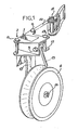
- this console In a known manner, this console, generally designated by 2, comprises at its anterior end a removable horizontal stud 3 intended to serve as an axis of articulation and as a connecting member with an unwinding member and, in particular , with a structure carrying a pulley 4. It also has a rear bearing face 2 and is associated with a flexible link 6, such as a strap, one of the ends of which is intended to cooperate with a tensioning mechanism at pawl 11, while the other end can cooperate with an anchoring means.
- a removable horizontal stud 3 intended to serve as an axis of articulation and as a connecting member with an unwinding member and, in particular , with a structure carrying a pulley 4. It also has a rear bearing face 2 and is associated with a flexible link 6, such as a strap, one of the ends of which is intended to cooperate with a tensioning mechanism at pawl 11, while the other end can cooperate with an anchoring means.
- the console shown in Figures 1 to 4 comprises, on either side of its support face 5, contact faces 7 which can cooperate with the flexible link 6. It is also provided, in its part rear, of two removable vertical studs, respectively 8 and 9, arranged symmetrically on either side of this bearing face.
- One of these studs, and for example that 9, constitutes a hinge axis for the end rear of a connecting rod 10, the front end of which carries the ratcheting tension mechanism 11.
- the connecting rod 10 forms an assembly with the ratcheting mechanism 11.
- the console is provided of a yoke 12 which is crossed by a removable vertical stud 13 disposed in front of the stud 9.
- the flexible link 6 has, at one of its ends, a loop 6a which is crossed by the stud a movable 8 after the flexible link has surrounded the post as shown in FIGS. 3 and 4.
- the other end of the flexible link passes between the corresponding bearing face 7 and the stud 9, then after having bypassed the stud 13, is introduced in mechanism 11, as shown in Figure 2.
- the console 2 differs from the previous one by the fact that it comprises two lateral yokes 12 and two anterior studs 13a and 13b, which makes it possible, in addition to the removability of the posterior studs 8 and 9, on the one hand, to place the connecting rod 10 carrying the ratchet mechanism 11, either to the right or to the left of the console depending on the morphology of the worker (right-handed or left-handed), or to use two mechanisms 11, the two load-bearing connecting rods 10 of which are articulated, one on the stud 9, the other on the stud 10. Except for this constructive difference, the console is in all respects similar to that described with reference in FIGS. 1 to 4. Of course, when the console is associated with two ratchet mechanisms 11, the strap or the flexible link 6 has two free ends, without loop, each capable of cooperating with one of these mechanisms 11.
- the console has a bore 16 passing through its bearing face and allowing its fixing by a threaded member on any support.
- the means supporting the pulley 4 are constituted, in the embodiment shown in Figures 1 and 4, by a substantially vertical arm 17 whose upper end is articulated around the horizontal stud 3 and whose lower end carries a substantially axis horizontal 18, perpendicular to the previous one, projecting from the front of this arm and receiving the pulley 4.
- This pulley is associated with a latch 19 articulated on the axis 3 at the same time as the lever 17.
- the arm 17 is composed of two parts, respectively upper 17a and lower 17b, connected to each other by interlocking, with articulation, about a horizontal axis 20 parallel to the axis 18 of the pulley. Thanks to this arrangement, when laying a cable 22 on a succession of posts 23, as shown in FIG. 6, the parts 17b of the arms 17 of the end brackets 2a can pivot to set substantially in alignment with the bisectors x'-x of the angle formed, at each end of the line being laid, by the horizontal and inclined parts of the cable 22. This prevents the corresponding console 2a from being subjected to stresses torsion tending to move it relative to the post and to communicate abnormal forces to it
- FIG. 8 shows that the console 2 with its removable axis 3 can be used to receive a traditional unwinding assembly consisting of a flange 23 carrying a horizontal axis 24 for the pulley 4 and associated with a return 25 with latch 260 On this return is mounted free in rotation a vertical hook 27 with latch 28.
- This figure therefore shows that the console according to the invention can be used with a traditional pulley if the user so desires.
- the assembly formed by the connecting rod 10 and the ratchet mechanism 11 is completely independent of the console itself, which allows the user to choose the mechanism that suits him, to replace this mechanism as necessary and to have it, either on the right, on the left, or on either side of the console, when it has the shape shown in Figure 5.
- this console can be fixed immediately against any post without the need to carry out several manipulations, as is the case with current consoles.
Landscapes
- Pivots And Pivotal Connections (AREA)
- Seats For Vehicles (AREA)
Applications Claiming Priority (2)
| Application Number | Priority Date | Filing Date | Title |
|---|---|---|---|
| FR8203359A FR2522208A1 (fr) | 1982-02-24 | 1982-02-24 | Console pour la suspension temporaire d'un organe de deroulement pour cables |
| FR8203359 | 1982-02-24 |
Publications (1)
| Publication Number | Publication Date |
|---|---|
| EP0088031A2 true EP0088031A2 (fr) | 1983-09-07 |
Family
ID=9271453
Family Applications (1)
| Application Number | Title | Priority Date | Filing Date |
|---|---|---|---|
| EP19830420013 Withdrawn EP0088031A2 (fr) | 1982-02-24 | 1983-01-26 | Console pour la suspension temporaire d'un organe de déroulement pour câbles |
Country Status (2)
| Country | Link |
|---|---|
| EP (1) | EP0088031A2 (OSRAM) |
| FR (1) | FR2522208A1 (OSRAM) |
Cited By (1)
| Publication number | Priority date | Publication date | Assignee | Title |
|---|---|---|---|---|
| FR2503067A1 (fr) * | 1981-03-31 | 1982-10-08 | Lienart Jean Pierre | Moyens de suspension d'un support de poulie pour le deroulage de cables |
-
1982
- 1982-02-24 FR FR8203359A patent/FR2522208A1/fr active Granted
-
1983
- 1983-01-26 EP EP19830420013 patent/EP0088031A2/fr not_active Withdrawn
Cited By (1)
| Publication number | Priority date | Publication date | Assignee | Title |
|---|---|---|---|---|
| FR2503067A1 (fr) * | 1981-03-31 | 1982-10-08 | Lienart Jean Pierre | Moyens de suspension d'un support de poulie pour le deroulage de cables |
Also Published As
| Publication number | Publication date |
|---|---|
| FR2522208A1 (fr) | 1983-08-26 |
| FR2522208B3 (OSRAM) | 1985-02-15 |
Similar Documents
| Publication | Publication Date | Title |
|---|---|---|
| EP0296898B1 (fr) | Dispositif de fixation d'une chaussure sur une pédale de bicyclette | |
| CH664675A5 (fr) | Chaussure de ski. | |
| EP0300955B1 (fr) | Dispositif de tension d'un câble de serrage d'une chaussure de ski | |
| FR2673148A1 (fr) | Siege amovible de vehicule. | |
| FR2489159A1 (fr) | Talonniere pour fixation de ski de securite | |
| FR2479166A1 (fr) | Dispositif d'accrochage d'une piece prefabriquee en beton a un engin de levage | |
| EP0492116A1 (fr) | Chaussure de ski alpin à entrée par l'arrière | |
| FR2607677A1 (fr) | Dispositif de fermeture d'une chaussure de ski | |
| EP0577925B1 (fr) | Dispositif de blocage d'une tige de chaussure de ski | |
| FR2704037A1 (fr) | Dispositif d'accrochage et de décrochage rapide et à distance. | |
| FR2467499A1 (fr) | Outil pour denuder un conducteur electrique de son revetement isolant | |
| EP0015862A1 (fr) | Chaussure de ski | |
| FR2577118A1 (fr) | Chaussure de ski du type a entree par l'arriere | |
| EP0088031A2 (fr) | Console pour la suspension temporaire d'un organe de déroulement pour câbles | |
| FR2740507A1 (fr) | Dispositif de securite pour echelle et echelle equipee d'un tel dispositif | |
| FR2564414A1 (fr) | Dispositif de fixation d'une chaussure sur une pedale, et chaussure et pedale ainsi equipees | |
| FR2596287A2 (fr) | Frein a ski | |
| FR2504084A1 (fr) | Bome de foc ballon ou " spinnaker " | |
| FR2574875A1 (fr) | Dispositif pour fixer des charges sur le toit d'un vehicule | |
| FR2543639A1 (fr) | Changement de vitesse avec butee de positionnement angulaire pour cycles et vehicules similaires | |
| FR2548615A1 (fr) | Pince pour installation de transport par cables comportant une pluralite de cables paralleles porteurs-tracteurs | |
| FR2587553A1 (fr) | Dispositif de suspension pour le deroulage, la mise en tension et le soutien d'un cable electrique torsade lourd equipe d'un cable porteur | |
| FR2662731A1 (fr) | Dispositif pour l'elingage de panneaux de coffrage. | |
| EP1737726A1 (fr) | Dispositif d' accrochage deverrouillable sous charge pour ceinture trapeze pour la pratique de la voile | |
| FR2547568A1 (fr) | Monte-materiaux a equipage mobile deplacable verticalement et horizontalement |
Legal Events
| Date | Code | Title | Description |
|---|---|---|---|
| PUAI | Public reference made under article 153(3) epc to a published international application that has entered the european phase |
Free format text: ORIGINAL CODE: 0009012 |
|
| AK | Designated contracting states |
Designated state(s): AT BE DE GB IT SE |
|
| STAA | Information on the status of an ep patent application or granted ep patent |
Free format text: STATUS: THE APPLICATION HAS BEEN WITHDRAWN |
|
| 18W | Application withdrawn |
Withdrawal date: 19850109 |
|
| RIN1 | Information on inventor provided before grant (corrected) |
Inventor name: PEVEL, MARC Inventor name: RIBEYRE, PIERRE |