EP0087901A2 - Connector for fluid communication - Google Patents
Connector for fluid communication Download PDFInfo
- Publication number
- EP0087901A2 EP0087901A2 EP83300887A EP83300887A EP0087901A2 EP 0087901 A2 EP0087901 A2 EP 0087901A2 EP 83300887 A EP83300887 A EP 83300887A EP 83300887 A EP83300887 A EP 83300887A EP 0087901 A2 EP0087901 A2 EP 0087901A2
- Authority
- EP
- European Patent Office
- Prior art keywords
- obturator
- face
- coupling
- valve
- faces
- Prior art date
- Legal status (The legal status is an assumption and is not a legal conclusion. Google has not performed a legal analysis and makes no representation as to the accuracy of the status listed.)
- Withdrawn
Links
Images

Classifications
-
- A—HUMAN NECESSITIES
- A62—LIFE-SAVING; FIRE-FIGHTING
- A62B—DEVICES, APPARATUS OR METHODS FOR LIFE-SAVING
- A62B9/00—Component parts for respiratory or breathing apparatus
- A62B9/02—Valves
-
- A—HUMAN NECESSITIES
- A61—MEDICAL OR VETERINARY SCIENCE; HYGIENE
- A61M—DEVICES FOR INTRODUCING MEDIA INTO, OR ONTO, THE BODY; DEVICES FOR TRANSDUCING BODY MEDIA OR FOR TAKING MEDIA FROM THE BODY; DEVICES FOR PRODUCING OR ENDING SLEEP OR STUPOR
- A61M39/00—Tubes, tube connectors, tube couplings, valves, access sites or the like, specially adapted for medical use
- A61M39/22—Valves or arrangement of valves
- A61M39/26—Valves closing automatically on disconnecting the line and opening on reconnection thereof
Definitions
- This invention relates to connectors which are concerned to establish a connection for fluid communication, for example, between tubes or between a tube and a container where it is essential that contamination shall not enter into the tube.
- one or both of the valve defining parts may have a retaining element and the relative movement for opening up the duct once the coupling is connected may be assured by relative movement of the obturators and the retaining element(s).
Landscapes
- Health & Medical Sciences (AREA)
- Pulmonology (AREA)
- Heart & Thoracic Surgery (AREA)
- General Health & Medical Sciences (AREA)
- Animal Behavior & Ethology (AREA)
- Veterinary Medicine (AREA)
- Hematology (AREA)
- Life Sciences & Earth Sciences (AREA)
- Anesthesiology (AREA)
- Engineering & Computer Science (AREA)
- Public Health (AREA)
- Biomedical Technology (AREA)
- Business, Economics & Management (AREA)
- Emergency Management (AREA)
- Quick-Acting Or Multi-Walled Pipe Joints (AREA)
- Apparatus For Making Beverages (AREA)
- Hydraulic Clutches, Magnetic Clutches, Fluid Clutches, And Fluid Joints (AREA)
- Joints That Cut Off Fluids, And Hose Joints (AREA)
Abstract
A valved coupling for establishing fluid connection between two separate but couplable elements (A, B) has minimum included volume between the parts that meet together to establish that connection. This is achieved by forming the faces (4, 24) of obturators (2, 14) which meet face-to-face upon coupling to be exactly the same as each other in profile extent and boundary shape, the same being true of the marginal faces (9, 22) around the obturators which belong to valve members (1, 15) coacting with the latter, the obturators and valve members being relatively movable. Furthermore, each transition from obturator face to marginal face is smooth (collinear). Coupling means (10, 21) ensure that the elements come together with the obturators and valve members in register, respectively.
Description
- This invention relates to connectors which are concerned to establish a connection for fluid communication, for example, between tubes or between a tube and a container where it is essential that contamination shall not enter into the tube.
- A particular application is the connection of a drinking bottle to a tube deriving from a respirator and through which the wearer of the respirator will drink. In an extreme case the respirator may be being worn and the coupling be required when protection is needed from nuclear, biological and chemical ("NBC") conditions.
- The connector proposed will however find application in other less extreme circumstances, for example in forming sterile couplings between items of medical equipment or items for chemical processing where considerable purity is required.
- The difficulty is of course that standard connectors involve penetration of one element by the other in which case the penetrating element will usually have been exposed to the atmosphere and will carry contamination into the other element and/or the entrapping between the two parts of the coupling of a volume of the ambient atmosphere which is thus introduced as an impurity into the conduit formed by the connection. This is clearly intolerable where effectively total sterility or where protection against NBC conditions is required.
- The present invention provides maximum security even in very extreme conditions by reducing to a line or lines the area from which external contaminants, carried on or in the vicinity of either the two elements of the coupling which are to be mated together, may be transferred into a fluid flow established through the coupling. This is achieved by having a valve member on each of the two coupling elements of the connector and an obturator normally sealing the extreme end of the duct-operable between it and the valve member, the members being relatively movable so as to permit a valving action. Each of the obturators has a face which precisely corresponds in profile, extent and boundary with the other, and the coupling elements have means for bringing those two faces into exact face-to-face registry with each other upon the mating together of the coupling elements. The margin around each obturator offered by the valve member also precisely correspond as between the two coupling elements of the connector and come into face-to-face contact upon the mating of the couplingelements. Thus upon the mating of the coupling elements an overall intimate fit is formed between the two obturators and the two marginal portions and this is interrupted only by a line or lines where the obturators seat on their respective marginal portions. There is therefore an absolutely minimal included volume between the two (this minimal included volume being provided wholly by the inevitable crack or tolerance where the extreme end of the obturator seats on the marginal portion). In a second stage of the connection the mated couplings are activated externally, to cause a relative movement of the obturators and the marginal portions whereby a duct is opened up between those parts.
- To assure the mating of the coupling parts in register one or both of the valve defining parts may have a retaining element and the relative movement for opening up the duct once the coupling is connected may be assured by relative movement of the obturators and the retaining element(s).
- This relative movement may be axial or may be rotational; the conenctor may establish a single or a double duct.
- All the-faces may be planar and coplanar; but other profiles are possible provided they correspond exactly from one element to the other.
- A subsidiary aspect of the invention concerns the need for compensating for liquid withdrawn from a drinking bottle when that is being used under NBC conditions. Air cannot simply be admitted from the ambient atmosphere since it would contaminate the liquid. This is why we may, therefore, provide a double duct between the drinking bottle and the respirator.
- A particular embodiment of the invention will now be described with reference to the accompanying drawings, wherein:
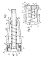
- Figure 1 is a diammetrical section through the two coupling elements of a first connector before being mated together, and
- Figure 2 is the same section of the two elements mated and with the duct open.
- -Looking now at the embodiment, the connector has two coupling elements generally labelled A and B.
- Considering first the element B, a cylinder 1 houses a cup-
like obturator 2 which is circular in transverse section. At one or more points around its diameter the cup has an axially extending inset slot 3. The mouth of the cylinder has an inwardly tapering valve-formingp'art 5 onto which seats a corresponding shaped portion 6 of thecup 2. These parts are very precisely formed so as to avoid any possibility of leak path between them. - The cylinder 1 is secured to or forms part of a closure 7 of a drinking bottle or to another duct- forming part with which it is desired to make a connection, a
spring 8 being entrapped between that and thecup 2 to urge the cup towards the closed position where theparts 5 and 6 seat together. Theextreme end face 4 of the cup is smoothly planar. Themarginal portions 9 of the valve element defined by thepart 5 are exactly co-planar with it when the cup is in the closed position, i.e. when the valve formed by it is seated. There is thus a single circular line of intersection between the obturator (the cup 2) and the valve member (the mouth 5) at the extreme end of the duct formed by the latter, and the face of the obturator and the face of the marginal portions of the valve are exactly collinear across each transition from one to the other. When, as here, the faces are planar, all such transitions are in a single plane. - On the outside of the cylinder 1 there is formed around its end portion retaining means 10 such as a screw thread or the slot or stud of a bayonet fitting, by which the other coupling element A can be retained in mating relationship with the element B.
- Turning-now to this other element A, an obturator is formed by a
stem 11 which is hollow so as to offer aduct 22 which at one end opens axially, within an end portion of the stem having means 12 for retaining on it a tube to form a continuation of the duct. At the other end theduct 22 opens through aradial port 13. Thestem 11 has at its extreme end beyond the port an outwardly flared part 14 which acts as obturator to a valve member in the form of acollar 15 which slides on the stem and has aflared mouth part 16 corresponding precisely to the conformation of the flared end part 14 of the stem. The collar is urged to the closed position of the valve thus formed, by aspring 17 surrounding the stem and entrapped between that collar and abushing 18. This bushing lies within theend wall 19 of a cup-like second retainingelement 20 which has on the internal periphery of its other end portion retaining means 21 for coupling with the retaining means 10. External bush 18' also surrounds the stem where it penetrates theend wall 19. - The
end face 24 of the portion 14 of the stem is exactly planar as also is the end face of themarginal portion 22 of thecollar 15 surrounding it and therefore the sealing effected at the extreme end of the duct formed between them is effectively at a single circular line, in that plane. This line is exactly co-extensive and registrable with the similar line between thefaces - To establish the connection the two elements are mated together and retained using the retaining means 21,10. This involves an overall contraction in the length of the couplings between the end cap 7 of one element and the end wall J9 of the other. The retaining means 10,21 cause the
faces corresponding surface 16 of thecollar 15 and the surface 6 of thepart 4 from thesurface 5 thereby opening up fluid communication in the element B through the grooves 3, between the respective obturators and their seating surfaces and (in the element A) through theradial port 13. The movements of thecup 2 relative to its valve seat and of thecollar 15 relative to its valve seat are not necessarily exactly equal but a sufficient degree of equality can be assured by appropriate choice of the spring rate of thesprings - It will be seen that due to the construction of the extreme ends of the ducts formed through the valve members there is substantially zero included or transferable volume when the connection is established. Even if contaminants are present on the exposed
faces - It is to be noted that the void within the
sleeve 20 which is open to the ambient atmosphere is not part of the duct which is formed through that coupling element. - This principle of line-only tranferability into the stream may also be embodied in double-duct arrangements and in those where seating or unseating is accomplished by rotational rather than axial movement.
Claims (6)
1. A coupling for establishing fluid connection therethrough including two separate elements (A,B) each containing an obturator (2,14) seatable on a valve seat (5,16) to act as a valve to close off a duct through that element, the valve seat being provided by a valve member (1,15) surrounding the obturator, and means (10,21) for coupling the two elements together to establish the connection characterised in that the face (4) on the obturator (2) on one element (B) corresponds exactly with a face (24) on the obturator (14) of the other element (A), a margin face (9) on the valve member (1) on one element (B) surrounding the face (4) of the obturator(2) of that element (B) corresponding exactly with a margin face (22) of the valve member (15) on the other element (A) which surrounds the face (24) .of the obturator of that other element, the coupling means (10,21) being effective upon formation of.the coupling to place the obturator faces (4,24) on the one hand and the margin faces (9,22) on the other in register, respectively.
2. A coupling according to Claim 1, wherein the obturator face (4,24) and the margin face (9,22) are collinear across all transitions between them, in the seated condition of the valves.
3. A coupling according to Claim 2, where in the said faces (4,24,9,22) are all planar and, for each element (A or B) respectively, coplanar in the seated condition of the valves.
4. A coupling according to Claim 1, Claim 2 or Claim 3 wherein each element has a body part (1,20), the coupling means (10,21) being on the body parts and causing upon coupling of the body parts a reduction in their overall length, coupling thereby causing unseating of the obturator (2) of the one element (B) by relative movement due to its contact with the face (4) of the obturator (14) of the other element (A), and also causing unseating of the valve member (15) of the other element-(A) by virtue of contact between its marginal face (22) and the marginal face (9) of the body part (1) of the one element (A).
5. A coupling according to Claim 4, wherein the obturator (2,15) of each element (A,B) is resiliently urged to its seated,'valve-closing position, the resilient means (17) in one element (A) acting between the body part (20) and the valve member (15), the latter being mounted on a stem (11) which is a continuation of the obturator and being entrapped by the obturator.
6. A coupling according to any one of the preceding Claims, wherein the coupling means (10,21) are screw-threadedly engageable together.
Applications Claiming Priority (2)
| Application Number | Priority Date | Filing Date | Title |
|---|---|---|---|
| GB8205718 | 1982-02-26 | ||
| GB8205718 | 1982-02-26 |
Publications (2)
| Publication Number | Publication Date |
|---|---|
| EP0087901A2 true EP0087901A2 (en) | 1983-09-07 |
| EP0087901A3 EP0087901A3 (en) | 1984-10-10 |
Family
ID=10528639
Family Applications (1)
| Application Number | Title | Priority Date | Filing Date |
|---|---|---|---|
| EP83300887A Withdrawn EP0087901A3 (en) | 1982-02-26 | 1983-02-21 | Connector for fluid communication |
Country Status (9)
| Country | Link |
|---|---|
| EP (1) | EP0087901A3 (en) |
| JP (1) | JPS58160690A (en) |
| KR (1) | KR840003425A (en) |
| AU (1) | AU1187383A (en) |
| DK (1) | DK94183A (en) |
| FI (1) | FI830634L (en) |
| GB (1) | GB2116277B (en) |
| NO (1) | NO155754C (en) |
| YU (1) | YU45283A (en) |
Cited By (6)
| Publication number | Priority date | Publication date | Assignee | Title |
|---|---|---|---|---|
| DE3800620A1 (en) * | 1987-03-10 | 1988-06-23 | Michael M Dr Med Schikorski | Valve coupling for connection of injection, puncturing and indwelling cannulas to syringes and tubing lines for use in human and veterinary medicine |
| WO1994005366A1 (en) * | 1992-09-07 | 1994-03-17 | Bespak Plc | Connecting apparatus for medical conduits |
| EP0639389A1 (en) * | 1993-08-17 | 1995-02-22 | Franz A. Dieringer | Connector for joining flexible tubing |
| EP0798013A1 (en) * | 1996-03-29 | 1997-10-01 | Becton, Dickinson and Company | Valved adapter for medical access devices |
| EP0976419A1 (en) * | 1998-07-29 | 2000-02-02 | Laboratoire Aguettant | Connecting device for peritoneal dialysis line |
| WO2006043883A1 (en) * | 2004-10-22 | 2006-04-27 | Nhi Consulting Ab | Coupling device for transferring a fluid |
Families Citing this family (8)
| Publication number | Priority date | Publication date | Assignee | Title |
|---|---|---|---|---|
| GB9217591D0 (en) * | 1992-08-19 | 1992-09-30 | Rawlins Graham C | Improvements in or relating to couplings |
| HK1077154A2 (en) | 2003-12-30 | 2006-02-03 | Vasogen Ireland Ltd | Valve assembly |
| US20070088292A1 (en) | 2005-07-06 | 2007-04-19 | Fangrow Thomas F Jr | Medical connector with closeable male luer |
| US7998134B2 (en) | 2007-05-16 | 2011-08-16 | Icu Medical, Inc. | Medical connector |
| US9168366B2 (en) | 2008-12-19 | 2015-10-27 | Icu Medical, Inc. | Medical connector with closeable luer connector |
| US8679090B2 (en) | 2008-12-19 | 2014-03-25 | Icu Medical, Inc. | Medical connector with closeable luer connector |
| CN103124582B (en) | 2010-05-06 | 2016-01-20 | Icu医学有限公司 | There is the medical connector of closable luer connector |
| ES2664517T3 (en) | 2011-09-09 | 2018-04-19 | Icu Medical, Inc. | Medical connectors with fluid resistant coupling interfaces |
Citations (4)
| Publication number | Priority date | Publication date | Assignee | Title |
|---|---|---|---|---|
| GB555692A (en) * | 1942-06-01 | 1943-09-02 | Louis Thomas Hutchison Greig | Improvements in pipe couplings |
| GB576210A (en) * | 1944-06-12 | 1946-03-22 | Percival Edward Thomas | Improvements in self-sealing pipe couplings |
| US2451441A (en) * | 1945-03-28 | 1948-10-12 | Aeroquip Corp | Self-sealing coupling |
| US3074430A (en) * | 1960-11-16 | 1963-01-22 | Bendix Corp | Concentric self-sealing coupling |
-
1983
- 1983-02-21 EP EP83300887A patent/EP0087901A3/en not_active Withdrawn
- 1983-02-21 GB GB08304753A patent/GB2116277B/en not_active Expired
- 1983-02-25 JP JP58031704A patent/JPS58160690A/en active Pending
- 1983-02-25 DK DK94183A patent/DK94183A/en not_active Application Discontinuation
- 1983-02-25 AU AU11873/83A patent/AU1187383A/en not_active Abandoned
- 1983-02-25 FI FI830634A patent/FI830634L/en not_active Application Discontinuation
- 1983-02-25 YU YU00452/83A patent/YU45283A/en unknown
- 1983-02-25 KR KR1019830000781A patent/KR840003425A/en not_active Application Discontinuation
- 1983-02-25 NO NO830676A patent/NO155754C/en unknown
Patent Citations (4)
| Publication number | Priority date | Publication date | Assignee | Title |
|---|---|---|---|---|
| GB555692A (en) * | 1942-06-01 | 1943-09-02 | Louis Thomas Hutchison Greig | Improvements in pipe couplings |
| GB576210A (en) * | 1944-06-12 | 1946-03-22 | Percival Edward Thomas | Improvements in self-sealing pipe couplings |
| US2451441A (en) * | 1945-03-28 | 1948-10-12 | Aeroquip Corp | Self-sealing coupling |
| US3074430A (en) * | 1960-11-16 | 1963-01-22 | Bendix Corp | Concentric self-sealing coupling |
Cited By (9)
| Publication number | Priority date | Publication date | Assignee | Title |
|---|---|---|---|---|
| DE3800620A1 (en) * | 1987-03-10 | 1988-06-23 | Michael M Dr Med Schikorski | Valve coupling for connection of injection, puncturing and indwelling cannulas to syringes and tubing lines for use in human and veterinary medicine |
| WO1994005366A1 (en) * | 1992-09-07 | 1994-03-17 | Bespak Plc | Connecting apparatus for medical conduits |
| EP0639389A1 (en) * | 1993-08-17 | 1995-02-22 | Franz A. Dieringer | Connector for joining flexible tubing |
| EP0798013A1 (en) * | 1996-03-29 | 1997-10-01 | Becton, Dickinson and Company | Valved adapter for medical access devices |
| US5776113A (en) * | 1996-03-29 | 1998-07-07 | Becton Dickinson And Company | Valved PRN adapter for medical access devices |
| US5950986A (en) * | 1996-03-29 | 1999-09-14 | Becton, Dickinson And Company | Valved PRN adapter for medical access devices |
| EP0976419A1 (en) * | 1998-07-29 | 2000-02-02 | Laboratoire Aguettant | Connecting device for peritoneal dialysis line |
| FR2781683A1 (en) * | 1998-07-29 | 2000-02-04 | Aguettant Lab | CONNECTION DEVICE FOR PERITONEAL DIALYSIS LINE |
| WO2006043883A1 (en) * | 2004-10-22 | 2006-04-27 | Nhi Consulting Ab | Coupling device for transferring a fluid |
Also Published As
| Publication number | Publication date |
|---|---|
| GB8304753D0 (en) | 1983-03-23 |
| NO155754B (en) | 1987-02-16 |
| EP0087901A3 (en) | 1984-10-10 |
| JPS58160690A (en) | 1983-09-24 |
| YU45283A (en) | 1988-08-31 |
| GB2116277A (en) | 1983-09-21 |
| GB2116277B (en) | 1985-04-03 |
| NO830676L (en) | 1983-08-29 |
| KR840003425A (en) | 1984-09-08 |
| DK94183D0 (en) | 1983-02-25 |
| FI830634A0 (en) | 1983-02-25 |
| AU1187383A (en) | 1983-09-01 |
| FI830634L (en) | 1983-08-27 |
| NO155754C (en) | 1987-05-27 |
| DK94183A (en) | 1983-08-27 |
Similar Documents
| Publication | Publication Date | Title |
|---|---|---|
| EP0087901A2 (en) | Connector for fluid communication | |
| US6609696B2 (en) | Male luer valve | |
| JP3512718B2 (en) | Pipe fittings | |
| US4711268A (en) | Valve manifold | |
| JP3215923B2 (en) | Equipment adapter for refrigeration equipment | |
| US5443453A (en) | Stop-cock valve | |
| US5273071A (en) | Dry disconnect couplings | |
| JPH0425594Y2 (en) | ||
| CN101558258A (en) | Valve assembly and system | |
| JPH0327797B2 (en) | ||
| US20070251588A1 (en) | Poppet valve | |
| US4355653A (en) | Vented check valve | |
| US20050051235A1 (en) | Liquid delivery system of gas mask | |
| US4669497A (en) | Backflow preventing device | |
| US4846213A (en) | Drain through ball valve | |
| US4909271A (en) | Ultrahigh purity gas valve with encapsulated bellows | |
| CA1216213A (en) | Valve for use in a suction line | |
| US3734127A (en) | Stopcock-joint assembly | |
| US20230047183A1 (en) | Cap with dual valve aseptic seals | |
| JPH02154889A (en) | Female coupler for tube coupler | |
| EP1632264B1 (en) | Male luer valve | |
| JPH03140677A (en) | Valve, liquid control device and liquid flowback prevention device in cluding the former | |
| EP0102797A2 (en) | Improvements in valves for dispensers | |
| US5232009A (en) | Leak resistant plug valve | |
| US3844530A (en) | Valve fitting with valve actuating sealing means |
Legal Events
| Date | Code | Title | Description |
|---|---|---|---|
| PUAI | Public reference made under article 153(3) epc to a published international application that has entered the european phase |
Free format text: ORIGINAL CODE: 0009012 |
|
| AK | Designated contracting states |
Designated state(s): BE CH DE FR GB IT LI NL SE |
|
| PUAL | Search report despatched |
Free format text: ORIGINAL CODE: 0009013 |
|
| AK | Designated contracting states |
Designated state(s): BE CH DE FR GB IT LI NL SE |
|
| STAA | Information on the status of an ep patent application or granted ep patent |
Free format text: STATUS: THE APPLICATION IS DEEMED TO BE WITHDRAWN |
|
| 18D | Application deemed to be withdrawn |
Effective date: 19850611 |
|
| RIN1 | Information on inventor provided before grant (corrected) |
Inventor name: DAVIS, BRIAN EDWARD |