EP0087362B1 - Procédé pour réaliser un transformateur électrique, transformateur ainsi réalisé et roue pour le bobiner - Google Patents
Procédé pour réaliser un transformateur électrique, transformateur ainsi réalisé et roue pour le bobiner Download PDFInfo
- Publication number
- EP0087362B1 EP0087362B1 EP83400328A EP83400328A EP0087362B1 EP 0087362 B1 EP0087362 B1 EP 0087362B1 EP 83400328 A EP83400328 A EP 83400328A EP 83400328 A EP83400328 A EP 83400328A EP 0087362 B1 EP0087362 B1 EP 0087362B1
- Authority
- EP
- European Patent Office
- Prior art keywords
- core
- tube
- insulating tube
- transformer
- slot
- Prior art date
- Legal status (The legal status is an assumption and is not a legal conclusion. Google has not performed a legal analysis and makes no representation as to the accuracy of the status listed.)
- Expired
Links
- 238000004804 winding Methods 0.000 title claims abstract description 62
- 238000004519 manufacturing process Methods 0.000 title claims abstract description 9
- 238000000034 method Methods 0.000 claims abstract description 20
- 230000008569 process Effects 0.000 claims abstract description 11
- 229920003023 plastic Polymers 0.000 claims abstract description 8
- 239000004033 plastic Substances 0.000 claims abstract description 8
- 230000008878 coupling Effects 0.000 claims description 11
- 238000010168 coupling process Methods 0.000 claims description 11
- 238000005859 coupling reaction Methods 0.000 claims description 11
- 238000009413 insulation Methods 0.000 description 4
- 239000011111 cardboard Substances 0.000 description 3
- 239000000123 paper Substances 0.000 description 3
- 125000006850 spacer group Chemical group 0.000 description 3
- 229910052782 aluminium Inorganic materials 0.000 description 2
- XAGFODPZIPBFFR-UHFFFAOYSA-N aluminium Chemical compound [Al] XAGFODPZIPBFFR-UHFFFAOYSA-N 0.000 description 2
- 230000008901 benefit Effects 0.000 description 2
- 238000000605 extraction Methods 0.000 description 2
- 238000009434 installation Methods 0.000 description 2
- 239000000463 material Substances 0.000 description 2
- 229910052751 metal Inorganic materials 0.000 description 2
- 239000002184 metal Substances 0.000 description 2
- 230000007935 neutral effect Effects 0.000 description 2
- 230000009466 transformation Effects 0.000 description 2
- 241000422252 Cales Species 0.000 description 1
- RYGMFSIKBFXOCR-UHFFFAOYSA-N Copper Chemical compound [Cu] RYGMFSIKBFXOCR-UHFFFAOYSA-N 0.000 description 1
- 239000000853 adhesive Substances 0.000 description 1
- 230000001070 adhesive effect Effects 0.000 description 1
- 238000005452 bending Methods 0.000 description 1
- 230000007547 defect Effects 0.000 description 1
- 238000010586 diagram Methods 0.000 description 1
- 239000012212 insulator Substances 0.000 description 1
- 230000004048 modification Effects 0.000 description 1
- 238000012986 modification Methods 0.000 description 1
- 239000011087 paperboard Substances 0.000 description 1
- 230000002093 peripheral effect Effects 0.000 description 1
- 230000037452 priming Effects 0.000 description 1
- 238000005096 rolling process Methods 0.000 description 1
Images


Classifications
-
- H—ELECTRICITY
- H01—ELECTRIC ELEMENTS
- H01F—MAGNETS; INDUCTANCES; TRANSFORMERS; SELECTION OF MATERIALS FOR THEIR MAGNETIC PROPERTIES
- H01F5/00—Coils
- H01F5/02—Coils wound on non-magnetic supports, e.g. formers
-
- H—ELECTRICITY
- H01—ELECTRIC ELEMENTS
- H01F—MAGNETS; INDUCTANCES; TRANSFORMERS; SELECTION OF MATERIALS FOR THEIR MAGNETIC PROPERTIES
- H01F41/00—Apparatus or processes specially adapted for manufacturing or assembling magnets, inductances or transformers; Apparatus or processes specially adapted for manufacturing materials characterised by their magnetic properties
- H01F41/02—Apparatus or processes specially adapted for manufacturing or assembling magnets, inductances or transformers; Apparatus or processes specially adapted for manufacturing materials characterised by their magnetic properties for manufacturing cores, coils, or magnets
- H01F41/04—Apparatus or processes specially adapted for manufacturing or assembling magnets, inductances or transformers; Apparatus or processes specially adapted for manufacturing materials characterised by their magnetic properties for manufacturing cores, coils, or magnets for manufacturing coils
- H01F41/06—Coil winding
- H01F41/098—Mandrels; Formers
Definitions
- the present invention relates to a method for producing a single-phase or polyphase electrical transformer more particularly of the type in which the magnetic circuit defines at least one rectangular window.
- the invention also relates to a transformer produced according to the method below.
- the high and low voltage electrical circuits are wound around one or more insulating tubes, each in turn surrounding a magnetic core constituted by one of the branches of the magnetic circuit.
- each circuit can have its core and its insulating tube or else there is on the contrary only one core for each phase.
- Certain advantageous methods for producing such transformers do not make it possible either to produce the magnetic circuit around the electrical coils, or to thread the electrical circuits onto the magnetic cores at a certain stage in the production of the magnetic circuit. This is the case if the magnetic circuit with rectangular window consists of one or more strips of sheet metal rolled around the magnetic windows. According to such manufacturing methods, it is necessary to wind the electrical circuits around the magnetic core once the magnetic circuit is finished.
- US Pat. No. 2,968,445 teaches to set up around the core a thin toothed wheel carrying a cylindrical end piece surrounding the core.
- the gear-tip assembly is assembled from two halves along an axial joint plane.
- the toothed wheel being placed at one of the ends of the core, several layers of insulating paper are rolled around the end piece to make the insulating tube, then the electrical circuits are wound around the insulating tube.
- the two halves of the toothed wheel are then disassembled, and the latter is removed by axially extracting the half-ends from the insulating tube.
- the object of the invention is to remedy these drawbacks by proposing a method according to which the electrical windings are easy to install on the magnetic circuit and occupying almost the entire length of the core (s).
- the invention thus relates to a method for manufacturing a transformer comprising a magnetic frame comprising at least one core and at least one cylinder head which together define at least one substantially rectangular window, at least one high voltage electrical circuit and one low voltage electrical circuit.
- the magnetic circuit is produced, an insulating tube is placed around the core, at least one of the ends of which is detachably coupled to a removable drive wheel, and the electrical coils are wound by causing the rotation of the insulating tube via the drive wheel.
- the method is characterized in that one starts from an insulating plastic tube split along at least one line directed substantially axially, in that it spreads the slot to pass the magnetic core to the inside the tube, in that the slot is closed, and in that at this stage only, the drive wheel is put in place around the core by mechanically coupling it to the annular end of the insulating tube.
- the installation of the insulating tube is considerably simplified and it is both more rigid and better insulator. It is no longer necessary for the drive wheel to have a nozzle engaged inside the tube, so that at the end of winding, the drive wheel is easy to extract, and it is not necessary to provide additional core length for this purpose. The length of the core is therefore almost entirely available for windings.
- the transformer produced according to the above method and comprising at least one core and at least one cylinder head which together define at least one substantially rectangular window, at least one high voltage electrical circuit and at least one low voltage electrical circuit wound around at least one insulating tube placed around the core is characterized in that the insulating tube is made of plastic and has a single slot directed substantially axially, and can move apart elastically to allow passage the magnetic core through the slot.
- the insulating tube can thus be produced in one piece and its installation does not require any fixing operation.
- the wheel for rotating the insulating tube for implementing the method comprising two half-wheels intended to be assembled around a core belonging to a frame magnetic of the transformer, and to be coupled therein in rotation with an insulating tube intended to receive at least one electrical circuit of the transformer, is characterized in that on its face directed towards the core, said wheel has a bearing and centering surface on the insulating tube, an axial stop for the insulating tube, and means for rotationally coupling with the insulating tube.
- the toothed wheel simultaneously ensures the axial and radial positioning and the rotation drive of the insulating tube.
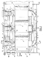
- the three-phase transformer is of the plane magnetic frame type 1 comprising three vertical rectilinear cores 2, the lower and upper ends of which are connected respectively by an upper magnetic yoke 3 and a lower magnetic yoke 4.
- This structure defines between the three cores 2 two rectangular magnetic windows 6.
- the magnetic frame is produced in a known manner from rolled strips of magnetic sheet. It comprises a ring 7 rolled around each window 6 and a peripheral ring 8 surrounding the two rings 7 at the same time.
- Each ring 7 or 8 having a semi-octagonal section, each ring 2 and each cylinder head 3 or 4 has the same octagonal section.
- each insulating tube 9 is arranged co-axially and at a slight distance around each core 2.
- each insulating tube 9 carries a low voltage winding 11 made of a strip of aluminum and a high voltage winding 13 made of copper wire, coaxial with the tube 9 and the core 2.
- the two windings 11 and 13 extend over almost the entire length of the core 2, the high voltage winding 13 being outside.
- an annular insulating spacer of known type not shown, which allows the circulation of the insulating oil in the axial direction between the windings.
- the active part of the transformer that is to say the assembly constituted by the frame 1 and the electrical windings 11, 13 is installed in a tank 14 containing insulating oil closed by an upper cover 16, and in which the nuclei 2 are vertical.
- the bottom 17 of the tank carries four longitudinal battens 18 and two transverse battens 19 intended to receive between them the magnetic frame 1 and to position it both in the longitudinal and transverse direction.
- the same device is found under the cover 16 where rubber blocks 21 are also interposed between each pair of cleats 18 and the frame 1 to ensure the elastic positioning of the latter in the vertical direction.
- the insulating tube 9 is made of plastic and is split along one of its degenerators 22.
- the profile of the slot 22 is sinuous, more precisely in step, so as to lengthen the electrical leakage line constituted by the slot sufficiently to avoid any possibility of priming between the electrical windings and the magnetic core 2.
- the tube 9 has a thinning forming a hinge.
- the insulating tube has two tenons 26 arranged on either side of the slot 22 and adjacent to it. This. Each tenon 26 has on the side of the slot 22 a face 27 carried by a plane passing through the axis of the tube 22, so that the slot 22 is closed, the two tenons 26 of one end are joined. Seen from above, they then together have a substantially semi-circular shape. As shown in FIG. 4, each annular end of the tube 9 extends axially from the windings 11 and 13 over a length equal to the thickness of the studs 26. In service, these are arranged laterally against the internal winding 11. The face 27 of the pins 26 is in a plane perpendicular to the plane of the frame 1.
- Each annular end of the tube 9 is associated with an annular shim 28 or 29 (FIG. 4) interposed between the annular end of the electrical circuits 11, 13 and the adjacent magnetic yoke 3 or 4.
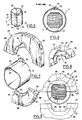
- the shim 28, taken as an example, is shown in a very simplified manner in FIGS. 8 and 9.
- the shim 28 comprises two half-shims 31, 32 of generally semi-circular shape.
- the joint plane 33 between the half shims 31 and 32 is carried by the median longitudinal plane CC of the frame 1 (FIG. 9).
- the shim On its annular face directed towards the core 2, the shim has a bearing surface 34 whose contour corresponds to the profile of the core 2, so that when the half-shims 31, 32 are assembled around the latter, the shim 28 has no freedom of radial or rotary movement relative to the frame 1.
- the surface 34 is octagonal like the core 2.
- the oblique faces 36 of the surface 34 are recessed to avoid contact with the core 2, which simplifies the centering problems. Only the faces of the surface 34 which are parallel or perpendicular to the plane CC are in contact with the core 2 and ensure positioning. In service, the surface 34 is located between the annular end of the tube 9 and the adjacent cylinder head 3 or 4.
- the wedge 28 also has on its face directed towards the core a second bearing surface 37 closer axially to the windings 11 and 13 than the face 34.
- the face 37 which is further from the axis of the core 2 than the face 34, is connected thereto by a shoulder 38.
- the face 37 ' which is cylindrical and has a diameter equal to the external diameter of the tube 9, bears on the external face of the latter and more precisely on the part of the tube 9 which protrudes from the windings 11 and 13.
- the width of the surface 37 is equal to the length of the tube 9 which protrudes from the windings 11 and 13.
- the half-shim 31 In position offset by 90 ° relative to the joint plane 33, the half-shim 31 has a semi-circular recess 39 whose shape corresponds to that of the two studs 26 assembled.
- the thickness e of the wedge 28 is equal to the distance separating the windings 11 to 13 from the adjacent cylinder head 3 or 4 in service.
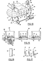
- each half-shim 31 or 32 comprises a web 43 which is substantially plane in the zone 40 bearing against the magnetic yoke 3 or 4.
- the veil 43 On its face directed towards the windings 11, 13 , the veil 43 carries fins 44 located on either side of the central opening of the wedge, and oriented perpendicular to the plane CC. On this same face, the veil 43 also carries fins 46 parallel to the fins 44 and extending from the central opening of the wedge 28.
- the central opening of the wedge 28 is delimited by an octagonal cutout of the web 43, the edge of which constitutes the surface 34 of bearing against the magnetic core 2.
- the surface 37 for supporting the wedge 28 on the tube 9 is produced at the end of the fins 46 directed towards the central opening of the wedge 28.
- each of these ends forms a staircase constituted by a part of the face 36, a part of the shoulder 38 and a part of the surface 37.
- the surface 37 further comprises a cylindrical sector in the middle of which the notch 39 is formed.
- the veil 43 carries on its face turned towards the adjacent cylinder head 3 or 4, fins 48 oriented obliquely with respect to the plane CC.
- the orientation of the fins 48 carried by one of the half-shims 31, 32 on one side of the opening of the shim 28 is symmetrical with respect to the plane CC of that carried by the other half-shim 31 or 32 on the same side of the central opening of the shim 28, and is identical to that of the fins 48 carried by the other half-shim 31 or 32 on the other side of the central opening of the shim 28.
- the fins 48 are lying in the direction of extraction of the half-shims, so that if one tends to extract the half-shims, they oppose this extraction by bending against the adjacent magnetic yoke 3 or 4.
- the web 43 is curved (FIGS. 12a to 14), in the direction opposite to the windings 11, 13.
- the two half-shims 31 and 32 are assembled according to a stepped joint plane, for the benefit of the robustness and the precision of the assembly.
- the fins 44 carried by each half-shim 31 or 32 are each aligned with one of the fins 44 carried by the other half-shim.
- the fin 44 closest to the central opening of the wedge 28, called fin 44a is thicker than the others and traversed by a bore, threaded with respect to the half-wedge 32, which makes it possible to screw together the two half shims 31, 32 by means of superpolyamide screws.
- the half-shims 31, 32 have a rectangular notch 49 intended to allow the lateral face of the windings 11 to 13 to appear and to allow the connections to exit.
- Each half-wedge 31 or 32 carries on the side opposite to the windings 11 to 13, a U-shaped mount 51 attached by its edge to the veil 43. The central part of the mount is located between the central opening of the wedge 28 and the notch 49, while its two arms are directed opposite the central opening.
- Each of the legs of the frame 51 carries two snap holes 52 ( Figure 12a).
- the mount 51 of the half-shim 32 is used to carry two supports 53, 54 intended in turn to carry coupling members between the low voltage windings of the transformer. As shown in FIG.
- the support 53 carries a blade 56 electrically connected to the internal end of the winding 11.
- the end of the support 53 also carries a blade 57 electrically connected to the blade 56 and connecting the latter to a low voltage phase terminal 58 arranged on one of the end side walls of the tank 14 ( Figure 2).
- Two other blades 59 surrounded by insulation ( Figure 4) are mounted against the blade 57 and each connect the winding 11 assigned to one of the other two cores 2 to a respective phase terminal arranged next to the terminal 58 ( Figure 2).
- the support 54 carries a blade 62 connected to the other end of the winding 11 and a longitudinal blade 63 electrically coupling the blades 62 of the three windings 11 of the transformer.
- the blade 63 is electrically connected to a neutral terminal 64 fitted at the end of the transformer below the terminals 58 and 61 (FIG. 1).
- the frame 51 of the half-block 31 does not carry any accessories. Through the notch 49 of this half-shim passes one of the end wires 66 of the high-voltage winding 13. Each of the wires 66 is connected directly to a high-voltage phase terminal 67 (FIG. 4) arranged in the cover 16 of tank 14 just above the corresponding notch 49.
- the shim 29 carries a housing 68 forming part of a switching device 69 making it possible to adjust the transformation ratio of the transformer.
- the device 69 is shown diagrammatically in FIG. 17 in which we see the three windings 13 coupled in a star between each of the terminals 67 and a conductive rod 71 carrying a contact 72 opposite each of the windings 13.
- each winding 13 On the side of this rod, each winding 13 carries three output contacts 73, one connected to the end of winding 13, the other connected to a turn located below this end and the third to a turn even further from the end of the winding.
- the contacts 73 are arranged for each winding 13 in a housing 68.
- the conductive rod 71 is slidably mounted between each of these housings 68 and a cover 74 which closes it ( Figure 16). In service, the rod is located between the windings 11, 13 and the bottom of the tank, next to the cylinder head 4.
- the rack 71 is connected to a cable 76 mounted in a sheath 77 and connected to a rotary control button 78 placed under the terminal 64 ( Figure 1).
- the rod 71 carries a rack 79 directed towards the bottom of the tank 14, which cooperates with a toothed wheel 81 to which is attached the end of a helical spring 82 ( Figure 4) whose other end is fixed to the housing 68.
- the spring 82 permanently biases the pinion 81 in the direction of the tension of the cable 76, the adjustments being locked by an appropriate device of known type provided in the control button 78 (FIG. 1).
- An insulating tube 9 is then placed around one of the cores 2, drawing aside the slot 22, passing the core 2 through the slot 22 and then closing the slot 22 when the core 2 is in the tube 9.
- the hinge 23 allows the semi-cylindrical half-shells constituting the tube 9 to pivot relative to one another during these operations.
- a drive toothed wheel 83 (FIGS. 7 and 10) is then placed at each end of the tube 9 formed of two half-wheels separated by a joint plane passing substantially through the axis of the wheel 83.
- the two half wheels are intended to be screwed together with the core 2 and the end of the tube 9 to which the wheel 83 is assigned.
- the wheel 83 is provided with two bores 88 which pass through the joint plane 87 between the half-wheels 84 and 85.
- the bores 88 are tapped in the half-wheel 85 (the teeth of which are not shown) and are embedded in a well 89 opening into the teeth (shown in part only) of the half-wheel 84.
- the wheel 83 On its annular face directed towards the core 2, the wheel 83 has a cylindrical surface 91 intended to bear all around the annular end of the tube 9.
- the axial dimension of the surface 91 corresponds to the length of tube 9 which must exceed windings 11, 13.
- the half-wheel 84 In position offset by 90 ° relative to the joint plane 87, the half-wheel 84 has a notch 92 intended to receive the two studs 26 joined.
- the half-wheel 85 has, opposite the notch 92, a radial groove 93 going from the surface 91 to the toothed periphery of the wheel 83.
- the surface 91 is bordered by a flange 94 serving as a stop for the insulating tube 9.
- three toothed satellites 96 are installed around each of them.
- one of the satellites 96 is coupled to a motor 97 while the two others simply ensure the centering of the wheels 83.
- one carries on the side opposite to the tube 9 a collar 98 intended to position the wheels 83 axially.
- the conductive strip 99 is then brought to the end of which a transverse conductive strip has been fixed which constitutes on each side of the strip 99 a blade 56 which is engaged in the groove 93 of the adjacent drive wheel 83.
- One of the blades 56 will then constitute the phase contact blade of the winding (see FIG. 4), while the other (not visible in FIG. 10), which can be much shorter, is used only for driving. of the band 99 by the wheels 83.
- the strip 99 consists of an aluminum tape covered with a sheet of insulating paper intended to electrically isolate the turn in progress from the next turn.
- the neutral coupling blade 63 (figure 4) is fixed at the end of it, which is engaged in the groove 93 of the wheel 83 (figure 10).
- plastic insulating spacer (not shown) of known type, analogous to a ladder that would have bent to bring these two ends.
- the winding 13 is then produced around this spacer 13 in a manner which, as regards the arrangement of the turns and their mutual insulation, is analogous to that described in US Pat. No. 2,968,445.
- the contacts 73 are connected where provided.
- the wheels 83 are dismantled, and the windings are carried out in the same way around the other two cores 2.
- the transformer which has just been described is thus particularly easy to produce, light, compact and efficient.
- the insulating tube 9 is very easy to put in place, and also makes it possible to provide only a very small space between the winding 11 and the core 2.
- this process for producing the windings at using the tube 9 almost the entire length of the cores 2 is occupied by the windings.
- the wedges 28 and 29, which cleverly cooperate with the tube 9 alone provide all the functions of positioning the windings relative to the magnetic frame 1.
- the very precise positioning ensured in this way makes it possible to reduce the safety margins provided for the spaces insulation, which is advantageous in lightness and performance.
- thermo-siphon between the windings Thanks to the fins 44 and 46, as well as the curved parts of the web 43 playing the role of oil deflectors, a real circulation of oil can be established by thermo-siphon between the windings.
- the insulating tube prefferably carry means for rotationally coupling with the drive wheels and chocks.
- This coupling could for example be effected by a thin projection carried by the wheels and the wedges and engaging in the slot 22.
- the insulating tube can consist of two completely separate shells. On the contrary, it may only consist of an elastic shell without hinge.
Landscapes
- Engineering & Computer Science (AREA)
- Power Engineering (AREA)
- Manufacturing & Machinery (AREA)
- Insulating Of Coils (AREA)
- Arrangements For Transmission Of Measured Signals (AREA)
- Coils Of Transformers For General Uses (AREA)
Priority Applications (1)
| Application Number | Priority Date | Filing Date | Title |
|---|---|---|---|
| AT83400328T ATE19708T1 (de) | 1982-02-19 | 1983-02-16 | Verfahren zur herstellung eines elektrischen transformators, danach hergestellter transformator, und rad zum wickeln. |
Applications Claiming Priority (2)
| Application Number | Priority Date | Filing Date | Title |
|---|---|---|---|
| FR8202753 | 1982-02-19 | ||
| FR8202753A FR2522189A1 (fr) | 1982-02-19 | 1982-02-19 | Procede pour realiser un transformateur electrique, transformateur ainsi realise et roue pour le bobiner |
Publications (2)
| Publication Number | Publication Date |
|---|---|
| EP0087362A1 EP0087362A1 (fr) | 1983-08-31 |
| EP0087362B1 true EP0087362B1 (fr) | 1986-05-07 |
Family
ID=9271154
Family Applications (1)
| Application Number | Title | Priority Date | Filing Date |
|---|---|---|---|
| EP83400328A Expired EP0087362B1 (fr) | 1982-02-19 | 1983-02-16 | Procédé pour réaliser un transformateur électrique, transformateur ainsi réalisé et roue pour le bobiner |
Country Status (5)
| Country | Link |
|---|---|
| EP (1) | EP0087362B1 (ja) |
| AT (1) | ATE19708T1 (ja) |
| CA (1) | CA1227326A (ja) |
| DE (2) | DE87362T1 (ja) |
| FR (1) | FR2522189A1 (ja) |
Families Citing this family (3)
| Publication number | Priority date | Publication date | Assignee | Title |
|---|---|---|---|---|
| FR2561033B1 (fr) * | 1984-03-06 | 1988-11-10 | Beisser Jean Claude | Transformateur et son procede de fabrication |
| EP0457933B1 (de) * | 1990-05-21 | 1995-05-03 | SIEMENS MATSUSHITA COMPONENTS GmbH & CO. KG | Spulenkörper |
| CN1069992C (zh) * | 1994-11-04 | 2001-08-22 | 松下电器产业株式会社 | 线路滤波器 |
Family Cites Families (11)
| Publication number | Priority date | Publication date | Assignee | Title |
|---|---|---|---|---|
| GB548548A (en) * | 1941-04-11 | 1942-10-14 | Kolster Brandes Ltd | Moulded coil former |
| FR1007119A (fr) * | 1948-02-26 | 1952-05-02 | Système électromagnétique, ayant notamment la forme d'un transformateur | |
| GB756021A (en) * | 1951-05-04 | 1956-08-29 | Henleys Telegraph Works Co Ltd | Improvements in or relating to bobbins for coil winders |
| US2709051A (en) * | 1951-09-26 | 1955-05-24 | Western Electric Co | Apparatus for coiling filamentary articles |
| US2807874A (en) * | 1954-06-09 | 1957-10-01 | Ona W Morris | Method for making bobbins |
| US2985392A (en) * | 1958-07-10 | 1961-05-23 | Texas Instruments Inc | Apparatus for winding a coil on a closed core |
| FR1266062A (fr) * | 1960-07-22 | 1961-07-07 | Procédé pour former les bobines sur des noyaux de fer | |
| CH451323A (de) * | 1966-03-31 | 1968-05-15 | Siemens Ag | Mehrteiliger Spulenkörper, insbesondere für Relais |
| GB1194805A (en) * | 1967-01-19 | 1970-06-10 | Osaka Onkyo Kabushiki Kaisha | Improvements in or relating to Bobbins |
| FR2177863B1 (ja) * | 1972-03-25 | 1977-04-29 | Philips Nv | |
| JPS5678105A (en) * | 1979-11-30 | 1981-06-26 | Ichiro Ooyama | Bobbin for closed loop core type transformer, etc. |
-
1982
- 1982-02-19 FR FR8202753A patent/FR2522189A1/fr active Granted
-
1983
- 1983-02-16 EP EP83400328A patent/EP0087362B1/fr not_active Expired
- 1983-02-16 DE DE198383400328T patent/DE87362T1/de active Pending
- 1983-02-16 DE DE8383400328T patent/DE3363342D1/de not_active Expired
- 1983-02-16 AT AT83400328T patent/ATE19708T1/de not_active IP Right Cessation
- 1983-02-18 CA CA000421946A patent/CA1227326A/fr not_active Expired
Also Published As
| Publication number | Publication date |
|---|---|
| ATE19708T1 (de) | 1986-05-15 |
| CA1227326A (fr) | 1987-09-29 |
| DE3363342D1 (en) | 1986-06-12 |
| DE87362T1 (de) | 1983-12-08 |
| FR2522189A1 (fr) | 1983-08-26 |
| EP0087362A1 (fr) | 1983-08-31 |
| FR2522189B1 (ja) | 1984-04-20 |
Similar Documents
| Publication | Publication Date | Title |
|---|---|---|
| EP0096058B1 (fr) | Transformateur electrique et procede pour sa fabrication | |
| EP0313514B1 (fr) | Procédé de fabrication d'un stator sans rainures pour moteur électrique et moteur électrique comprenant un stator fabriqué selon le procédé | |
| FR2613884A1 (fr) | Machine electrique comprenant un paquet de toles supportant un enroulement, et procede pour sa fabrication | |
| FR2531821A1 (fr) | Machine a collecteur a courant continu et procede pour sa fabrication | |
| FR2533376A1 (fr) | Enroulement d'induit en galette en spirale pour une machine dynamoelectrique et son procede de fabrication | |
| EP0087362B1 (fr) | Procédé pour réaliser un transformateur électrique, transformateur ainsi réalisé et roue pour le bobiner | |
| EP0248798B1 (fr) | Moteur electrique synchrone a rotor aimante et procede de fabrication de ce moteur | |
| CH648961A5 (fr) | Noyau magnetisable destine a recevoir des conducteurs electriques dans une machine electrique, et procede pour la fabrication de ce noyau. | |
| FR2561033A1 (fr) | Transformateur et son procede de fabrication | |
| EP0087363B1 (fr) | Transformateur électrique | |
| CH665303A5 (en) | Superimposed printed-circuit coil assembly - has sepd. terminals in corresp. positions on opposite faces of insulating disc with printed connection for distinct winding portions | |
| FR2864716A1 (fr) | Stator d'une machine tournante electrique | |
| FR3065125A1 (fr) | Moteur electrique synchrone et procede d'assemblage de ce moteur electrique | |
| WO1991010244A1 (fr) | Transformateur de type torique | |
| FR2516717A1 (fr) | Rotor a poles saillants pour machine dynamoelectrique avec bobines demontables sans demontage des poles | |
| FR2939559A1 (fr) | Dispositif de roulage de bobine electromagnetique | |
| FR2504318A1 (fr) | Lame conductrice pour collecteurs de machines electriques tournantes et son procede de fabrication | |
| EP0990295B2 (fr) | Procede de bobinage et bobines pour machine electrique tournantes | |
| WO2022069096A1 (fr) | Rotor de machine electrique et procede d'assemblage d'un tel rotor | |
| FR2492153A1 (fr) | Transformateur de petite taille | |
| CH515647A (fr) | Rotor pour moteur électrique à collecteur et procédé de fabrication de celui-ci | |
| FR2816122A1 (fr) | Machine electrique tournante pour vehicule comprenant un induit muni d'un paquet de toles recevant dans chaque encoche un fil interne et un fil peripherique | |
| WO2023041403A1 (fr) | Guide de bobinage pour rotor de machine électrique | |
| FR2674062A3 (fr) | Bobinage electrique et son procede de fabrication. | |
| FR3105642A1 (fr) | Pièce bobinée de machine électrique tournante |
Legal Events
| Date | Code | Title | Description |
|---|---|---|---|
| PUAI | Public reference made under article 153(3) epc to a published international application that has entered the european phase |
Free format text: ORIGINAL CODE: 0009012 |
|
| 17P | Request for examination filed |
Effective date: 19830219 |
|
| AK | Designated contracting states |
Designated state(s): AT BE CH DE GB IT LI LU NL SE |
|
| TCAT | At: translation of patent claims filed | ||
| TCNL | Nl: translation of patent claims filed | ||
| ITCL | It: translation for ep claims filed |
Representative=s name: BARZANO' E ZANARDO ROMA S.P.A. |
|
| DET | De: translation of patent claims | ||
| GRAA | (expected) grant |
Free format text: ORIGINAL CODE: 0009210 |
|
| ITF | It: translation for a ep patent filed | ||
| AK | Designated contracting states |
Kind code of ref document: B1 Designated state(s): AT BE CH DE GB IT LI LU NL SE |
|
| REF | Corresponds to: |
Ref document number: 19708 Country of ref document: AT Date of ref document: 19860515 Kind code of ref document: T |
|
| REF | Corresponds to: |
Ref document number: 3363342 Country of ref document: DE Date of ref document: 19860612 |
|
| PLBE | No opposition filed within time limit |
Free format text: ORIGINAL CODE: 0009261 |
|
| STAA | Information on the status of an ep patent application or granted ep patent |
Free format text: STATUS: NO OPPOSITION FILED WITHIN TIME LIMIT |
|
| 26N | No opposition filed | ||
| ITTA | It: last paid annual fee | ||
| PGFP | Annual fee paid to national office [announced via postgrant information from national office to epo] |
Ref country code: GB Payment date: 19930202 Year of fee payment: 11 |
|
| PGFP | Annual fee paid to national office [announced via postgrant information from national office to epo] |
Ref country code: AT Payment date: 19930211 Year of fee payment: 11 |
|
| PGFP | Annual fee paid to national office [announced via postgrant information from national office to epo] |
Ref country code: SE Payment date: 19930215 Year of fee payment: 11 |
|
| PGFP | Annual fee paid to national office [announced via postgrant information from national office to epo] |
Ref country code: CH Payment date: 19930223 Year of fee payment: 11 |
|
| PGFP | Annual fee paid to national office [announced via postgrant information from national office to epo] |
Ref country code: NL Payment date: 19930228 Year of fee payment: 11 |
|
| PGFP | Annual fee paid to national office [announced via postgrant information from national office to epo] |
Ref country code: LU Payment date: 19930310 Year of fee payment: 11 |
|
| PGFP | Annual fee paid to national office [announced via postgrant information from national office to epo] |
Ref country code: BE Payment date: 19930329 Year of fee payment: 11 |
|
| PGFP | Annual fee paid to national office [announced via postgrant information from national office to epo] |
Ref country code: DE Payment date: 19930428 Year of fee payment: 11 |
|
| EPTA | Lu: last paid annual fee | ||
| PG25 | Lapsed in a contracting state [announced via postgrant information from national office to epo] |
Ref country code: LU Free format text: LAPSE BECAUSE OF NON-PAYMENT OF DUE FEES Effective date: 19940216 Ref country code: GB Effective date: 19940216 Ref country code: AT Effective date: 19940216 |
|
| PG25 | Lapsed in a contracting state [announced via postgrant information from national office to epo] |
Ref country code: SE Effective date: 19940217 |
|
| PG25 | Lapsed in a contracting state [announced via postgrant information from national office to epo] |
Ref country code: LI Effective date: 19940228 Ref country code: CH Effective date: 19940228 Ref country code: BE Effective date: 19940228 |
|
| BERE | Be: lapsed |
Owner name: SOC. NOUVELLE TRANSFIX S.A.. Effective date: 19940228 |
|
| PG25 | Lapsed in a contracting state [announced via postgrant information from national office to epo] |
Ref country code: NL Effective date: 19940901 |
|
| GBPC | Gb: european patent ceased through non-payment of renewal fee |
Effective date: 19940216 |
|
| NLV4 | Nl: lapsed or anulled due to non-payment of the annual fee | ||
| REG | Reference to a national code |
Ref country code: CH Ref legal event code: PL |
|
| PG25 | Lapsed in a contracting state [announced via postgrant information from national office to epo] |
Ref country code: DE Effective date: 19941101 |
|
| EUG | Se: european patent has lapsed |
Ref document number: 83400328.7 Effective date: 19940910 |