EP0087124B1 - Process and apparatus for producing easily dyeable polyester false-twisted yarns - Google Patents
Process and apparatus for producing easily dyeable polyester false-twisted yarns Download PDFInfo
- Publication number
- EP0087124B1 EP0087124B1 EP19830101510 EP83101510A EP0087124B1 EP 0087124 B1 EP0087124 B1 EP 0087124B1 EP 19830101510 EP19830101510 EP 19830101510 EP 83101510 A EP83101510 A EP 83101510A EP 0087124 B1 EP0087124 B1 EP 0087124B1
- Authority
- EP
- European Patent Office
- Prior art keywords
- yarn
- false
- polyester yarn
- spun
- heater
- Prior art date
- Legal status (The legal status is an assumption and is not a legal conclusion. Google has not performed a legal analysis and makes no representation as to the accuracy of the status listed.)
- Expired
Links
- 229920000728 polyester Polymers 0.000 title claims description 108
- 238000000034 method Methods 0.000 title claims description 63
- 230000008569 process Effects 0.000 title claims description 49
- 239000000835 fiber Substances 0.000 claims description 146
- 238000010438 heat treatment Methods 0.000 claims description 127
- 238000009987 spinning Methods 0.000 claims description 90
- 238000001816 cooling Methods 0.000 claims description 77
- -1 polyethylene terephthalate Polymers 0.000 claims description 37
- 229920000139 polyethylene terephthalate Polymers 0.000 claims description 34
- 239000005020 polyethylene terephthalate Substances 0.000 claims description 34
- 229920001519 homopolymer Polymers 0.000 claims description 14
- 239000000203 mixture Substances 0.000 claims description 3
- 229920001577 copolymer Polymers 0.000 claims description 2
- 239000000470 constituent Substances 0.000 claims 3
- 239000000975 dye Substances 0.000 description 24
- 238000004043 dyeing Methods 0.000 description 20
- QQVIHTHCMHWDBS-UHFFFAOYSA-N isophthalic acid Chemical compound OC(=O)C1=CC=CC(C(O)=O)=C1 QQVIHTHCMHWDBS-UHFFFAOYSA-N 0.000 description 18
- 230000001965 increasing effect Effects 0.000 description 15
- 238000004804 winding Methods 0.000 description 14
- 229920001634 Copolyester Polymers 0.000 description 12
- 238000010586 diagram Methods 0.000 description 11
- 230000000694 effects Effects 0.000 description 11
- 239000004744 fabric Substances 0.000 description 11
- LYCAIKOWRPUZTN-UHFFFAOYSA-N Ethylene glycol Chemical compound OCCO LYCAIKOWRPUZTN-UHFFFAOYSA-N 0.000 description 10
- 238000002844 melting Methods 0.000 description 10
- 230000008018 melting Effects 0.000 description 10
- 230000000087 stabilizing effect Effects 0.000 description 10
- KKEYFWRCBNTPAC-UHFFFAOYSA-N Terephthalic acid Chemical compound OC(=O)C1=CC=C(C(O)=O)C=C1 KKEYFWRCBNTPAC-UHFFFAOYSA-N 0.000 description 8
- 230000015572 biosynthetic process Effects 0.000 description 8
- 229910052751 metal Inorganic materials 0.000 description 7
- 239000002184 metal Substances 0.000 description 7
- QPFMBZIOSGYJDE-UHFFFAOYSA-N 1,1,2,2-tetrachloroethane Chemical compound ClC(Cl)C(Cl)Cl QPFMBZIOSGYJDE-UHFFFAOYSA-N 0.000 description 6
- MTHSVFCYNBDYFN-UHFFFAOYSA-N diethylene glycol Chemical compound OCCOCCO MTHSVFCYNBDYFN-UHFFFAOYSA-N 0.000 description 6
- 230000006872 improvement Effects 0.000 description 6
- 238000011144 upstream manufacturing Methods 0.000 description 6
- 238000002441 X-ray diffraction Methods 0.000 description 5
- 239000002253 acid Substances 0.000 description 5
- 125000003118 aryl group Chemical group 0.000 description 5
- 239000000986 disperse dye Substances 0.000 description 5
- LLLVZDVNHNWSDS-UHFFFAOYSA-N 4-methylidene-3,5-dioxabicyclo[5.2.2]undeca-1(9),7,10-triene-2,6-dione Chemical compound C1(C2=CC=C(C(=O)OC(=C)O1)C=C2)=O LLLVZDVNHNWSDS-UHFFFAOYSA-N 0.000 description 4
- WNLRTRBMVRJNCN-UHFFFAOYSA-N adipic acid Chemical compound OC(=O)CCCCC(O)=O WNLRTRBMVRJNCN-UHFFFAOYSA-N 0.000 description 4
- 230000007547 defect Effects 0.000 description 4
- 230000004927 fusion Effects 0.000 description 4
- 238000009998 heat setting Methods 0.000 description 4
- 230000014759 maintenance of location Effects 0.000 description 4
- 238000007789 sealing Methods 0.000 description 4
- CXMXRPHRNRROMY-UHFFFAOYSA-N sebacic acid Chemical compound OC(=O)CCCCCCCCC(O)=O CXMXRPHRNRROMY-UHFFFAOYSA-N 0.000 description 4
- QTBSBXVTEAMEQO-UHFFFAOYSA-N Acetic acid Chemical compound CC(O)=O QTBSBXVTEAMEQO-UHFFFAOYSA-N 0.000 description 3
- MUBZPKHOEPUJKR-UHFFFAOYSA-N Oxalic acid Chemical compound OC(=O)C(O)=O MUBZPKHOEPUJKR-UHFFFAOYSA-N 0.000 description 3
- ISWSIDIOOBJBQZ-UHFFFAOYSA-N Phenol Chemical compound OC1=CC=CC=C1 ISWSIDIOOBJBQZ-UHFFFAOYSA-N 0.000 description 3
- DNIAPMSPPWPWGF-UHFFFAOYSA-N Propylene glycol Chemical compound CC(O)CO DNIAPMSPPWPWGF-UHFFFAOYSA-N 0.000 description 3
- 230000008859 change Effects 0.000 description 3
- 230000007423 decrease Effects 0.000 description 3
- 238000009826 distribution Methods 0.000 description 3
- 238000009940 knitting Methods 0.000 description 3
- 238000005259 measurement Methods 0.000 description 3
- 239000012046 mixed solvent Substances 0.000 description 3
- 239000008041 oiling agent Substances 0.000 description 3
- 230000003287 optical effect Effects 0.000 description 3
- 229920000642 polymer Polymers 0.000 description 3
- 230000005855 radiation Effects 0.000 description 3
- 230000009467 reduction Effects 0.000 description 3
- FJKROLUGYXJWQN-UHFFFAOYSA-N 4-hydroxybenzoic acid Chemical compound OC(=O)C1=CC=C(O)C=C1 FJKROLUGYXJWQN-UHFFFAOYSA-N 0.000 description 2
- PXHVJJICTQNCMI-UHFFFAOYSA-N Nickel Chemical compound [Ni] PXHVJJICTQNCMI-UHFFFAOYSA-N 0.000 description 2
- 229920003171 Poly (ethylene oxide) Polymers 0.000 description 2
- 238000010521 absorption reaction Methods 0.000 description 2
- 239000001361 adipic acid Substances 0.000 description 2
- 235000011037 adipic acid Nutrition 0.000 description 2
- 238000004458 analytical method Methods 0.000 description 2
- WERYXYBDKMZEQL-UHFFFAOYSA-N butane-1,4-diol Chemical compound OCCCCO WERYXYBDKMZEQL-UHFFFAOYSA-N 0.000 description 2
- 235000013351 cheese Nutrition 0.000 description 2
- 239000003795 chemical substances by application Substances 0.000 description 2
- 238000007334 copolymerization reaction Methods 0.000 description 2
- 239000013078 crystal Substances 0.000 description 2
- 230000005684 electric field Effects 0.000 description 2
- 230000009477 glass transition Effects 0.000 description 2
- WGCNASOHLSPBMP-UHFFFAOYSA-N hydroxyacetaldehyde Natural products OCC=O WGCNASOHLSPBMP-UHFFFAOYSA-N 0.000 description 2
- BDJRBEYXGGNYIS-UHFFFAOYSA-N nonanedioic acid Chemical compound OC(=O)CCCCCCCC(O)=O BDJRBEYXGGNYIS-UHFFFAOYSA-N 0.000 description 2
- 230000002035 prolonged effect Effects 0.000 description 2
- 230000000644 propagated effect Effects 0.000 description 2
- CYIDZMCFTVVTJO-UHFFFAOYSA-N pyromellitic acid Chemical compound OC(=O)C1=CC(C(O)=O)=C(C(O)=O)C=C1C(O)=O CYIDZMCFTVVTJO-UHFFFAOYSA-N 0.000 description 2
- 230000000630 rising effect Effects 0.000 description 2
- 125000001424 substituent group Chemical group 0.000 description 2
- 229920002994 synthetic fiber Polymers 0.000 description 2
- 239000012209 synthetic fiber Substances 0.000 description 2
- ARCGXLSVLAOJQL-UHFFFAOYSA-N trimellitic acid Chemical compound OC(=O)C1=CC=C(C(O)=O)C(C(O)=O)=C1 ARCGXLSVLAOJQL-UHFFFAOYSA-N 0.000 description 2
- HZUBBVGKQQJUME-UHFFFAOYSA-N 1,5-diamino-2-bromo-4,8-dihydroxyanthracene-9,10-dione Chemical compound O=C1C2=C(N)C(Br)=CC(O)=C2C(=O)C2=C1C(O)=CC=C2N HZUBBVGKQQJUME-UHFFFAOYSA-N 0.000 description 1
- FKUJGZJNDUGCFU-UHFFFAOYSA-N 2,5-dimethylterephthalic acid Chemical compound CC1=CC(C(O)=O)=C(C)C=C1C(O)=O FKUJGZJNDUGCFU-UHFFFAOYSA-N 0.000 description 1
- 229940090248 4-hydroxybenzoic acid Drugs 0.000 description 1
- 229910002483 Cu Ka Inorganic materials 0.000 description 1
- 239000004721 Polyphenylene oxide Substances 0.000 description 1
- YIMQCDZDWXUDCA-UHFFFAOYSA-N [4-(hydroxymethyl)cyclohexyl]methanol Chemical compound OCC1CCC(CO)CC1 YIMQCDZDWXUDCA-UHFFFAOYSA-N 0.000 description 1
- 238000002835 absorbance Methods 0.000 description 1
- 150000007513 acids Chemical class 0.000 description 1
- 239000000654 additive Substances 0.000 description 1
- 229910052782 aluminium Inorganic materials 0.000 description 1
- XAGFODPZIPBFFR-UHFFFAOYSA-N aluminium Chemical compound [Al] XAGFODPZIPBFFR-UHFFFAOYSA-N 0.000 description 1
- 239000002216 antistatic agent Substances 0.000 description 1
- 239000000981 basic dye Substances 0.000 description 1
- 230000005540 biological transmission Effects 0.000 description 1
- 238000009835 boiling Methods 0.000 description 1
- 125000002091 cationic group Chemical group 0.000 description 1
- 230000000052 comparative effect Effects 0.000 description 1
- 150000001875 compounds Chemical class 0.000 description 1
- 230000001143 conditioned effect Effects 0.000 description 1
- 238000010924 continuous production Methods 0.000 description 1
- 238000007796 conventional method Methods 0.000 description 1
- 239000006059 cover glass Substances 0.000 description 1
- 238000002788 crimping Methods 0.000 description 1
- 230000003247 decreasing effect Effects 0.000 description 1
- 239000002270 dispersing agent Substances 0.000 description 1
- 239000006185 dispersion Substances 0.000 description 1
- 229920006240 drawn fiber Polymers 0.000 description 1
- BXKDSDJJOVIHMX-UHFFFAOYSA-N edrophonium chloride Chemical compound [Cl-].CC[N+](C)(C)C1=CC=CC(O)=C1 BXKDSDJJOVIHMX-UHFFFAOYSA-N 0.000 description 1
- 230000002708 enhancing effect Effects 0.000 description 1
- 238000001125 extrusion Methods 0.000 description 1
- 239000012530 fluid Substances 0.000 description 1
- 239000011521 glass Substances 0.000 description 1
- 239000012770 industrial material Substances 0.000 description 1
- 230000000977 initiatory effect Effects 0.000 description 1
- 238000012423 maintenance Methods 0.000 description 1
- 238000004519 manufacturing process Methods 0.000 description 1
- 239000003595 mist Substances 0.000 description 1
- RXOHFPCZGPKIRD-UHFFFAOYSA-N naphthalene-2,6-dicarboxylic acid Chemical compound C1=C(C(O)=O)C=CC2=CC(C(=O)O)=CC=C21 RXOHFPCZGPKIRD-UHFFFAOYSA-N 0.000 description 1
- 229910052759 nickel Inorganic materials 0.000 description 1
- 235000006408 oxalic acid Nutrition 0.000 description 1
- 230000002093 peripheral effect Effects 0.000 description 1
- MTZWHHIREPJPTG-UHFFFAOYSA-N phorone Chemical compound CC(C)=CC(=O)C=C(C)C MTZWHHIREPJPTG-UHFFFAOYSA-N 0.000 description 1
- 229920000570 polyether Polymers 0.000 description 1
- 238000001028 reflection method Methods 0.000 description 1
- 238000011160 research Methods 0.000 description 1
- 238000009991 scouring Methods 0.000 description 1
- 238000004904 shortening Methods 0.000 description 1
- 229910052708 sodium Inorganic materials 0.000 description 1
- 239000011734 sodium Substances 0.000 description 1
- 239000003381 stabilizer Substances 0.000 description 1
- BDHFUVZGWQCTTF-UHFFFAOYSA-M sulfonate Chemical compound [O-]S(=O)=O BDHFUVZGWQCTTF-UHFFFAOYSA-M 0.000 description 1
- 125000001273 sulfonato group Chemical group [O-]S(*)(=O)=O 0.000 description 1
- 238000009864 tensile test Methods 0.000 description 1
- 238000012360 testing method Methods 0.000 description 1
- 230000007704 transition Effects 0.000 description 1
- 239000002699 waste material Substances 0.000 description 1
- XLYOFNOQVPJJNP-UHFFFAOYSA-N water Substances O XLYOFNOQVPJJNP-UHFFFAOYSA-N 0.000 description 1
- 238000009941 weaving Methods 0.000 description 1
Images








Classifications
-
- D—TEXTILES; PAPER
- D02—YARNS; MECHANICAL FINISHING OF YARNS OR ROPES; WARPING OR BEAMING
- D02G—CRIMPING OR CURLING FIBRES, FILAMENTS, THREADS, OR YARNS; YARNS OR THREADS
- D02G1/00—Producing crimped or curled fibres, filaments, yarns, or threads, giving them latent characteristics
- D02G1/02—Producing crimped or curled fibres, filaments, yarns, or threads, giving them latent characteristics by twisting, fixing the twist and backtwisting, i.e. by imparting false twist
- D02G1/0286—Producing crimped or curled fibres, filaments, yarns, or threads, giving them latent characteristics by twisting, fixing the twist and backtwisting, i.e. by imparting false twist characterised by the use of certain filaments, fibres or yarns
Definitions
- This invention relates to a process for producing a false-twisted polyester yarn wherein an as-spun polyester yarn is subjected in succession to heat treatment, cooling and then false twisting or draw-false twisting.
- Polyester fibers are excellent in mechanical and thermal properties and they have been used in not only the field of clothing articles but also the field of industrial materials.
- the polyester fibers are poor in the dyeability, and especially, fibers composed of a polyethylene terephthalate homopolymer are difficult to dye and they can be dyed only under a high pressure at a high temperature such as about 130°C.
- polyester fibers can be improved by copolymerizing polyethylene terephthalate with isophthalic acid having a metal sulfonate group or polyether.
- polyethylene terephthalate with isophthalic acid having a metal sulfonate group or polyether.
- these modified polyester fibers still cannot be dyed under normal pressure.
- FR-A-2 193 893 teaches a process of making a bulky yarn which comprises drawing an unsubstituted or partially substituted yarn and false-twist-crimping the drawn yarn by using a frictional twisting apparatus while sliding between the yarn and the frictional surface of the apparatus is avoided.
- FR-A-2 208 999 teaches a process for making a textured yarn by the simultaneous false-twisting and stretching of an unstretched or incompletely stretched yarn.
- FR-A-2 129 710 teaches the false-twisting of yarn wherein the yarn is drawn at a temperature of 50 to 150°C.
- CH-A-530 487 teaches a continuous process wherein a polyester yarn is drawn at a temperature of 90 to 170°C, the drawn yarn is cooled to room temperature, and the cooled yarn is subjected to false-twisting and simultaneously heat-setting at a temperature of 160°C to 230°C.
- a process for producing a false-twisted polyester yarn from a yarn consisting of an as-spun polyester fiber having a mean birefringence index (An) of at least 15x10- 3 but less than 150 X 10-', which has been spun at a spinning speed of at least 2,500 m/min but less than 7,000 m/min comprises continuously subjecting said yarn to (1) a preliminary heat treatment carried out in an atmosphere maintained at a temperature of 190°C to 300°C, (2) natural cooling conducted at a temperature of 20°C ⁇ 15°C for the period of A satisfying the following formula: wherein V stands for the spinning speed expressed in the unit of km/min, or forced cooling and (3) a false twisting or draw-false twisting operation.
- a false twisting apparatus which comprises a feed yarn creel, a false twisting heater and an optional stabilizing heater, a false twisting element and a winder, wherein a heat-treating heater of the non-contact type is arranged upstream of the false twisting heater and between the false twisting heater and the feed yarn creel, at a height substantially equal to the height of the feed yarn creel so that the heat-treating heater confronts the false twisting heater.
- polyester fiber used in the present invention means not only a fiber made of a polyethylene terephthalate homopolymer but also a fiber made of a copolyester comprising ethylene terephthalate as the main repeating unit component and up to 15% by weight of a third copolymerized component.
- At least one member selected from isophthalic acid, adipic acid, oxalic acid, trimellitic acid, pyromellitic acid, p-hydroxybenzoic acid, 2,6 - naphthalene - dicarboxylic acid, 5 - sodium - sulfoisophthalic acid, sebacic acid, azelaic acid and 2,5 - dimethyl - terephthalic acid may be used instead of a part of terephthalic acid
- at least one member selected from diethylene glycol, propylene glycol, 1,4-butanediol, 1,4-dihydroxymethylcyclohexane and polyoxyethylene glycol may be used instead of a part of ethylene glycol.
- a fiber of a polymer such as mentioned above used in the present invention may comprise additives customarily added to synthetic fibers, such as a delustering agent, an antistatic agent and a stabilizer.
- the dyeability of a fiber of a polyester comprising main repeating units of ethylene terephthalate and a third copolymerized component as mentioned above is improved over the dyeability of a fiber of a homopolyester of ethylene terephthalate, and the degree of the improvement of the dyeability varies according to the kind of the copolymerized component and the weight proportion thereof.
- an acid free of an aromatic ring such as adipic acid or sebacic acid
- an acid having a substituent as a side chain on the aromatic ring gives a higher degree of the improvement of the dyeability than an aromatic ring-containing acid free of such a substituent.
- a component having a higher molecular weight such as polyoxyethylene glycol
- a component having a lower molecular weight such as diethylene glycol
- the larger the weight proportion of the third component the higher the degree of the improvement of the dyeability.
- the dyeability of a polyester fiber is improved by copolymerization of a third component such as mentioned above, with increase of the proportion of the third component, spinning becomes difficult and the manufacturing cost is increased. Furthermore, the thermal and mechanical properties of the obtained copolyester fiber are lower than those of a fiber of a polyethylene terephthalate homopolymer. Moreover, if the weight proportion of the third copolymerized component exceeds 15%, the melting point is drastically lowered.
- the melting point of the resulting polyester fiber is 230°C or lower, and the heat resistance is drastically degraded with reduction of the mechanical properties.
- the weight proportion of the third copolymerized component should be up to 15%, preferably up to 5%, more preferably 0%. Namely, a polyethylene terephthalate homopolymer is most preferred.
- the polyester yarn used in the present invention is a multiflament yarn consisting of at least two single filaments.
- the size of the single filament is 0.01 to 10 deniers and the cross-section of the single filament may be either circular or non-circular.
- An as-spun polyester yarn having a An value of at least 15x10 -3 but less than 150x10 -3 may be obtained by performing spinning and winding at a spinning speed of at least 2,500 m/min but less than 7,000 m/min, for example, in an apparatus as shown in Fig. 1.
- reference numerals 1, 2, 3, 4, 5 and 6 represent a spin head, a spinneret, a spun filament being solidified, a fluid sucking device for cooling and sucking a bundle of filaments being solidified, a wound yarn package and a friction roll rotated at a surface speed equal to the winding speed.
- spinning speed is meant a surface speed of a winding friction roll 6 when the spinning-winding operation is carried out according to the apparatus shown in Fig. 1.
- the spinning operation conducted at a spinning speed of 7,000 m/min or higher is not advantageous from the industrial viewpoint because the equipment cost of the winding device is increased and close attention should be paid to the control and maintenance of various conditions at the spinning step. At the present, therefore, spinning speeds of less than 7,000 m/min are advantageous.
- the as-spun polyester yarn having a An value of at least 15x10 -3 but less than 150x10 -3 which is obtained by the above-mentioned spinning operation, is subjected to the heat treatment without passage through any special drawing step prior to the heat treatment.
- the heat treatment of the present invention is accomplished, for example, by heat-treating the polyester yarn having the above-mentioned An value in a heated tubular heater or slit heater without being contacted with the surface of the heater; passing the yarn through heated air or super-heated steam or allowing the yarn to travel while contacting it with a heated metal plate.
- the temperature of the heater is adjusted to 190 to 300°C.
- An optimum heat treatment temperature varies depending upon such factors as the An value of the fiber, the composition of the copolymer, the heat treatment time, the fiber elongation ratio, the fineness of the single filament and the fineness of the yarn.
- Fig. 3 shows the relationship between the spinning speed (m/min) and the An value of a 35-d/7-f multi-filament yarn having a filament section of a circular shape, which is obtained by spinning a polyethylene terephthalate homopolymer having an intrinsic viscosity of 0.63 dl/g as measured at 35°C in a 2/1 mixed solvent of phenol/tetrachloroethane at various spinning speeds by using the spinning apparatus shown in Fig. 1. From Fig. 3, it is seen that the spinning speed providing a An value of 50x10 -3 is about 4,000 m/min and the spinning speed providing a An value of 15x10 -3 is about 2,500 m/min.
- Fig. 3 shows the relationship between the spinning speed (m/min) and the An value of a 35-d/7-f multi-filament yarn having a filament section of a circular shape, which is obtained by spinning a polyethylene terephthalate homopolymer having an intrinsic viscosity of 0.63 dl
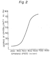
- a polyethylene terephthalate fiber spun at a spinning speed of at least about 4,000 m/min that is, a polyethylene terephthalate fiber having a ⁇ n value of at least 50x 10- 3 , has a X c value of at least 50%, and the structure of the fiber is substantially completed.
- a polyethylene terephthalate fiber spun at a spinning speed of at least about 2,500 but less than about 4,000 m/min may be regarded as an incomplete fiber in which the structure of the fiber is being formed.
- the polyester fiber having a An value of at least 15x10 -3 but less than 50x10 -3 that is, the polyester fiber spun at a spinning speed of at least about 2,500 but less than about 4,000 m/min, is different from the polyester fiber having a ⁇ n value of at least 50x 10- 3 , that is, the polyester fiber spun at a spinning speed of at least 4,000 m/min, and should be drawn at the heat treatment.
- a polyester fiber having a An value of less than 15x10- 3 that is, a polyester fiber spun at a spinning speed of less than about 2,500 m/min, is composed substantially of an amorphous portion and the degree of orientation of the molecule chain is low. Therefore, if this polyester fiber is subjected to the heat treatment according to the present invention, partial fusion is caused and the tenacity and elongation are extremely low.
- a polyethylene terephthalate homopolymer fiber having a An value of at least 50x10 -3 has a substantially completed fiber structure
- the heat-treated fiber comes to have an increased degree of crystallinity and an increased refractive index. Namely, the fiber structure is more completed.
- the structure of the amorphous region dominating the dyeability of the fiber is relaxed so that the fiber can be dyed even under normal pressure with a disperse dye.
- the dynamic loss tangent (tan ⁇ )-temperature characteristic is suitable for defining the structure of the amorphous portion.
- parameters of a polyester fiber before the false twisting treatment or the draw-false twisting treatment which are preferred from the viewpoint of the fine structure, are as follows. Namely, the peak value of tan ⁇ , i.e., (tan ⁇ )max, in the tan ⁇ -temperature curve is at least 0.10, the temperature T max at which tan ⁇ shows a peak is not higher than 115°C, the value of tan ⁇ at 220°C, i.e., tan ⁇ 220, is not more than 0.055, the value of X c is at least 50% and the value of An is at least 35x10 -3 .
- a fiber dyeable under normal pressure can be obtained.
- An as-spun polyester fiber spun at a spinning speed of less than about 4,500 m/min have the (tan ⁇ ) mx and T max values falling within the above-mentioned ranges, but tan ⁇ 220 exceeds 0.055 and both or either of X c and An is less than the above lower limit and the mechanical properties are low and the stability against heat is insufficient.
- the polyester fiber heat-treated according to the process of the present invention is characterized as possessing a (tan ⁇ ) max value of at least 0.10, a T max value not higher than 115°C, a tan ⁇ 220 value not more than 0.055, a X c value of at least 50% and a An value of at least 35x10 -3 , and, if cooling described below is performed, even after the false twisting treatment or draw-false twisting treatment, the polyester fiber can be dyed under normal pressure.
- the conditions of the heat treatment of an as-spun fiber having a An value of at least 50x10 -3 but less than 150x10- 3 for obtaining an easily dyeable polyethylene terephthalate fiber having the above-mentioned fine structure are as described hereinbefore, when the fiber is passed through a tubular or slit heater.
- the heater temperature be 230 to 270°C, more preferably 240 to 260°C
- the heat treatment time be 0.4 to 1.5 seconds, more preferably 0.6 to 1.3 seconds
- the elongation ratio be -8 to +3%, more preferably -6 to +1%.
- the fiber to be heat-treated is a copolyester fiber
- a temperature lower than the above-mentioned heat treatment temperature by the difference between the melting point of the polyethylene terephthalate fiber and the melting point of the copolyester fiber is adopted for the heat treatment.
- the melting point of a fiber obtained by copolymerizing polyethylene terephthalate with 5% by weight of isophthalic acid and spinning the copolyester at a spinning speed of 6,000 m/min is 247°C, which is lower by about 10°C than the melting point of a fiber of a polyethylene terephthalate homopolymer.
- a temperature suitably adopted for the heat treatment in the tubular heater is 230 to 250°C.
- the melting point of a fiber obtained by copolymerizing polyethylene terephthalate with 12% by weight of isophthalic acid and spinning the copolyester in the same manner as described above is 232°C, which is lower by about 25°C than the melting point of the fiber of a polyethylene terephthalate homopolymer, and a temperature suitable for the heat treatment of the fiber of this copolyester is 215 to 235°C.
- copolyesters as described above are sensitive to heat, and therefore, in the heat treatment of fibers of these copolyesters, close attention should be paid to the control of the heat treatment temperature.
- the treatment time and elongation ratio to be adopted for the heat treatment of copolyester fibers may be the same as those adopted for the heat treatment of fibers of a polyethylene terephthalate homopolymer.
- an ordinary as-spun polyester fiber having a An value of at least 15x10 -3 but less than 50x10- 3 and consisting of single filaments having a circular section and a size of at least 1 denier is not completed and the X c value is low.
- such a fiber should be drawn by 5 to 200% at the heat treatment. If the heat treatment is carried out without effecting this drawing, crystals are not sufficiently grown or developed, and therefore, the fiber is partially fused and the mechanical properties are drastically degraded.
- the above-mentioned fiber is heat-treated while drawing it by 5 to 200%, fusion of the fiber is not caused, and there is obtained a fiber to be preferably subjected to the false twisting treatment or draw-false twisting treatment in the present invention, in which the (tan 5) max value is at least 0.10, the T max value is less than 115°C, the tan 6 220 value is less than 0.055, the X c value is at least 50% and the An value is at least 50x10- 3 .
- the temperature adopted for heat-treating a polyester fiber spun at a spinning speed of at least 2,500 m/min but less than 4,000 m/min may be the same as the temperature to be adopted for heat-treating a polyethylene terephthalate homopolymer fiber spun at a spinning speed of at least 4,500 m/min.
- the heat treatment temperature be in the range of 190 to 270°C, more preferably 200 to 260°C.
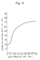
- Fig. 4 illustrates the relationship between the heat treatment time (second) and the X c value (%) of the fiber, which is observed when a polyethylene terephthalate homopolymer fiber spun at a spinning speed of 3,500 m/min is heat-treated in air heated at 260°C under an elongation ratio of 12%. From Fig. 4, it is seen that the X c value is increased as the treatment time is prolonged and if the heat treatment time is 0.2 second, the X c value is substantially equal to the X c value of the fiber spun at a spinning speed of 4,000 m/min, that is, 50%.
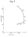
- Fig. 5 illustrates the relationship of the treatment time to (tan ⁇ ) max and T max values, which is observed when the above-mentioned fiber is heat-treated in the same manner as described above.
- the numerical values in Fig. 5 represent the heat treatment time (seconds). From Fig. 5, it is seen that with prolongation of the treatment time, (tan 8) max decreases but T max increases, and that if the treatment time is 0.2 to 0.3 second or longer, (tan o)max changes only to a minor extent but T max decreases.
- the heat treatment time region of up to 0.2-0.3 second is the region causing the structural change conventionally considered to be due to the heat treatment, that is, the region where the structure is made dense by the heat treatment. If the heat treatment time is further prolonged beyond the above region, crystals are developed but the amorphous portion is relaxed. This phenomenon is one discovered for the first time by us. Accordingly, in case of a polyester yarn spun at a spinning speed of at least 2,500 m/min but less than 4,000 m/min, it is necessary that the heat treatment time should be longer by at least 0.2 second than the heat treatment time for the polyester yarn spun at a spinning speed of at least 4,000 m/min, and thus, it is preferred that the polyester yarn be heat-treated for 0.4 to 2.0 seconds.
- the heat treatment temperature may be lowered according to the proportion of the copolymerized component as described above with respect to the polyester yarn spun at a spinning speed of at least 4,000 m/min.
- the foregoing heat treatment conditions are those for an ordinary polyester fiber in which the section of the filament has a circular shape and the size of the single filament is at least 1 denier.
- a polyester fiber having a non-circular section such as a triangular or pentagonal section or a polyester fiber having a circular section but a size smaller than 1 denier
- the heat treatment temperature may be lowered by about 5 to about 10°C or the treatment time may be shortened by 0.1 to 0.2 second.
- the heat treatment may also be carried out in super-heated steam or a mixed atmosphere of super-heated steam and hot air.
- the heat treatment time and the fiber elongation ratio during the heat treatment are the same as in case of the heat treatment conducted in the tubular or slit heater or heated air, but it is preferred that the heat treatment temperature be selected within the range of from (230 ⁇ 50Z)°C to (29050Z)°C in which Z stands for the mole fraction of super-heated steam in the heat-treating medium.
- the as-spun polyester filament yarn having a An value of at least 15x10- 3 but less than 150x10- 3 may be heat-treated in the twisted state.
- the twist number be at least 3% of the twist number at the false twisting treatment or draw-false twisting treatment.
- the twist number T at the false twisting treatment or draw-false twisting treatment is 80 to 120% of in which d represents the denier of the false-twisted yarn, and this twist number is the number of twists present between the false twisting heater and the false twisting element.
- this twisted polyester yarn may be heat-treated by passing it through the tubular heater without contact with the heater or by passing it through heated air, super-heated steam or a mixture thereof.
- the spinning speed is at least 4,000 m/min, the resulting yarn may be contacted with the heater during the heat treatment.
- the contact with a heated metal plate or the like is not preferred because formation of fluffs or local fusion of the fiber cannot be avoided.
- the heat treatment time can be shortened to about 0.2 second. Accordingly, the length of the heater can be shortened. In this case, if the heat treatment is carried out under no substantial drawing, the dyeability is further improved.
- the means for twisting the yarn in this embodiment there may be adopted a method in which the yarn is twisted before the heat treatment, but, when the false twisting treatment or draw-false twisting treatment is conducted successively after the heat treatment and cooling as in the present invention, there may preferably be adopted a manner wherein twists given by the false twisting are extended to the heat treatment zone.
- Figs. 6 and 7 illustrate embodiments in which the process of the present invention is carried out while twists given at the draw-false twisting step are extended to the heat treatment zone.
- a travelling yarn 7 unwound from a wound yarn package 5 is passed through a feed roller (R 1 ) 8 and through a heat-treating heater 9 provided with a metal plate while being contacted therewith.
- a feed roller (R 1 ) 8 When the yarn 7 is passed through the heat-treating heater 9, twists propagated from a false twisting element 14 are given to the yarn 7.
- the yarn 7 After the yarn 7 is heated in the heat-treating heater 9 in the twisted state, the yarn 7 is cooled by the atmosphere in the room and is guided into a false twisting heater 13 through a twist stop guide 11. If this cooling treatment is not effected and the twist stop guide 10 is not disposed, the drawing tension is extended into the heat-treating heater 9.
- the yarn is heated to a temperature higher than the glass transition point to initiate drawing. The point at which drawing is initiated is the drawing point 12.
- the yarn is cooled again by the atmosphere in the room, and just after passage through the false twisting element 14, the yarn is untwisted and is then wound through a delivery roller 15 to form a package 17 of the drawn and false-twisted yarn.
- reference numeral 16 represents a winding friction roller (R 3 ).
- Fig. 7 is a diagram illustrating another embodiment of the process of the present invention.
- the apparatus shown in Fig. 7 is the same as the apparatus shown in Fig. 6 except that the heat-treating heater 9 is of the non-contact heating type.
- the heat treatment temperature and drawing ratio are the same as those adopted in the heat treatment conducted in heated air. If the yarn is contacted with the heater surface, the heat treatment time may be shortened by about 0.2 second as compared with the heat-treatment time required when the fiber is not contacted with the heater surface.
- the An value of the polyester fiber exceeds 150x10-a, and any as-spun polyester yarn cannot have a An value exceeding 150x10 -3 . More specifically, as shown in Fig. 3, in case of the as-spun yarn, the An value is at a peak when the spinning speed is about 7,000 m/min and the peak An value is about 120x10- 3 . In the case where the filament denier is less than 1 denier, since the draft ratio is increased at the spinning step, even an as-spun yarn has a An value larger than that shown in Fig. 3 but the largest value is less than 150x10- 3 .
- an easily-dyeable false-twisted polyester yarn from a polyester fiber having a An value of at least 150x10-a, that is, a polyester fiber which has been drawn after the spinning step, according to a process similar to that of the present invention.
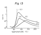
- the fine structure thereof especially the structure of the amorphous region, is very dense and compact, and ordinarily, as shown in Fig. 13, the (tan 8)max value is about 0.1 and the T max value is at least 130°C.
- the heat-treated polyester yarn be cooled continuously after the heat treatment.
- continuous used in the present invention, it is meant that after one stpe has been completed, a yarn is continuously transferred to the subsequent step without winding of the yarn, i.e., without interruption of the yarn travelling. Namely, the yarn which has been heat-treated in the above-mentioned manner is transferred to the cooling step without winding of the yarn.
- Either natural cooling or forced cooling may be adopted for cooling the heat-treated yarn.
- the yarn 7 travels in the room temperature atmosphere during the passage of from the slit heater 11 to the false twisting heater 11.
- natural cooling it is meant that the yarn 7 is cooled in the room temperature atmosphre while it travels from the outlet of the slit heater 9 to the inlet of the false twisting heater 13.
- the yarn 7 travels in the room temperature atmosphere during the passage of from the heater 9 to the false twisting heater 13.
- natural cooling it meant that the yarn 7 is cooled while it travels from the outlet of the slit heater 9 to the inlet of the false twisting heater 13.
- Adoption of natural cooling is advantageous in that a cooling device need not be disposed and the deviation of the quality among lots can be reduced.
- the cooling time (A) is important, and a good dyeability can always be attained if natural cooling is carried out so that the cooling time (A) satisfies the following requirement: wherein V stands for the spinning speed (km/min) for the polyester yarn.
- cooling time (A) used herein is meant a time required for the yarn to travel from the outlet of the heat-treating heater to the inlet of the false twisting heater.
- the cooling time (A) satisfies the above requirement is as follows.
- an as-spun polyester yarn having a An value of at least 15x 10- 1 but less than 50x10-3 that is, a polyester yarn spun at a spinning speed of at least about 2,500 m/min but less than about 4,000 m/min
- the X c value is small and the structure of the fiber is incomplete, and the yarn should be drawn in the heat treatment step.
- the yarn is drawn in the heat treatment step, if the yarn is subjected to the false twisting treatment or draw-false twisting treatment after the heat treatment without performing cooling, especially in case of a small elongation ratio, the molecule chain of the fiber which has been drawn and oriented in the heat treatment step is relaxed and the mechanical properties are often reduced. Accordingly, in the case where the heat treatment is carried out under elongation, that is, in case of a yarn spun at a spinning speed of at least about 2,500 m/min but less than about 4,000 m/min, cooling is especially preferred, and a relatively long cooling time is preferred.
- Drawing is not particularly necessary in case of a polyester yarn having a An value of at least 50x 10- 3 , that is, a polyester yarn spun at a spinning speed of at least about 4,000 m/min.
- the lower the spinning speed the less the relaxation of the amorphous region caused by the heat treatment, and the higher the spinning speed, the larger the relaxation of the amorphous region caused by the heat treatment. Accordingly, when the spinning speed is higher, the improvement of the dyeability by the heat treatment is increased.
- the as-spun polyester yarn spun at a spinning speed of at least about 4,000 m/min the higher the spinning speed, the more relaxed the amorphous region, and the dyeability is accordingly improved. Even this as-spun yarn, however, cannot be dyed under normal pressure before the heat treatment of the present invention.
- the structure is changed and the easily-dyeable structure of the amorphous region is completely formed. If cooling is not sufficient, the easily-dyeability structure is not completed, and if the yarn is subsequently guided to the false twisting or draw-false twisting step in the state where the easily dyeable structure is still incomplete, the easily dyeable structure being set is destroyed at the false twisting step or draw-false twisting step. In case of a fiber where the easily dyeable structure is completed by cooling after the heat treatment, even if the yarn is successively guided to the false twisting or draw-false twisting step, the good dyeability of the false-twisted yarn is maintained at a high level.
- the cooling time is shorter than in natural cooling, and forced cooling is advantageous in that the speed of the false-twisted yarn can be increased and the structure of the entire apparatus of the present invention can be made compact.
- forced cooling is meant cooling to be conducted by using any apparatus or device for increasing the cooling effect and shortening the cooling time. From the viewpoint of the cooling effect, a lower cooling temperature is preferred, and ordinarily, it is preferred that forced cooling be carried out at a temperature lower than the level causing dewing resulting in yarn unevenness, for example, at a temperature lower by 5 to 10°C than room temperature.
- the forced cooling method there can be mentioned a method in which a cold plate maintained at a temperature lower by 5 to 10°C than room temperature is inserted, for example, between the slit heater 9 and first feed roller (R 1 ) 10 shown in Fig.
- polyester yarn which has thus been heat-treated and subsequently cooled is continuously subjected to the false twisting treatment or draw-false twisting treatment.
- draw-false twisting treatment used in the present invention is meant a so-called in-draw-false twisting treatment where false twisting is carried out while simultaneously effecting drawing (that is, false twisting carried out at a draw ratio higher than 1.0).
- false twisting treatment is meant a false twisting treatment which is carried out at a draw ratio of up to 1.0.
- the false twisting system employed may be any of the conventional pin type, friction type and apron nip type false twisting systems. It is preferred that the twist number be about 80 to about 120% of in which d stands for the calculated denier of the yarn after the false twisting treatment, and that the temperature of the false twisting heater be 180 to 240°C.
- the heater temperature at the false twisting treatment or draw-false twisting treatment be lower than the heat treatment temperature. If the heater temperature at the false twisting or draw-false twisting treatment is higher than the temperature of the preceding heat treatment, it happens that the easily-dyeable structure of the fiber formed at the heat treatment and set at the cooling treatment is greatly changed to a structure of a poor dyeability. Of course, even if the heater temperature at the false twisting treatment or draw-false twisting treatment is lower than the heat treatment temperature, the structure of the fiber is changed more or less, but the good dyeability is not degraded at all.
- Whether or not the polyester yarn heat-treated and subsequently cooled is drawn at the false twisting step in the present invention is determined according to the elongation at break of the fiber after cooling. If the elongation at break of the fiber after cooling exceeds 30%, drawing is effected at the false twisting treatment. In contrast, if the elongation at break of the fiber is not more than 30%, the yarn is ordinarily overfed. As the elongation is high, the draw ratio is increased. The elongation at break of the fiber after cooling is changed according to the spinning speed and the heat treatment conditions, and ordinarily, a higher spinning speed, a higher heat treatment temperature and a higher drawing ratio at the heat treatment result in a lower elongation at break.
- the fine structure of the false-twisted yarn obtained according to the above-mentioned process of the present invention is characterized in that the amorphous region is relaxed. Namely, it now has been found that the (tan 6)ma, value determined from the tan 6-temperature curve is at least 0.08 and the relationship of (tan ⁇ ) max ⁇ 1 x 1 0-2 (T max -105) is established.
- the false-twisted polyester yarn having the above-mentioned structure for the amorphous region is rendered easily dyeable and capable of being dyed under normal pressure with a disperse dye.
- the amount of the dye adsorbed when the false-twisted yarn obtained according to the process of the present invention is dyed at 100°C for 60 minutes is equal to or larger than the amount of the dye adsorbed when a yarn obtained by subjecting a conventional drawn yarn of a polyethylene terephthalate homopolymer to a customary false twisting treatment is dyed at 130°C for 60 minutes. This property is evaluated according to a method described below.
- a false-twisted yarn of polyethylene terephthalate copolymerized with a metal sulfonate-containing compound, such as sodium sulfonated isophthalic acid, prepared according to the present invention can be dyed with a cationic or basic dye under normal pressure.
- the (tan ⁇ ) max value is about 0.10 and T max value is 130 to 140°C, and this false-twisted yarn cannot be dyed under normal pressure.
- the above-mentioned as-spun, polyester yarn is continuously subjected to heat treatment, cooling and false twisting or draw-false twisting.
- This process in which these three steps are continuously conducted is economically advantageous over the process in which these steps are conducted in a discontinuous manner, because the labor cost and energy cost can be reduced and the area occupied by the apparatus as a whole can be decreased. Moreover, handling of the yarn is facilitated and the frequency for a worker to touch the yarn is reduced, resulting in decrease of yarn defects.
- the threading property required for carrying out these three steps in a continuous manner is approximately similar to the threading property required for ordinary false twisting or draw-false twisting, and the collecting property of the yarn is rather increased by the heat treatment. Therefore, occurrence of yarn breakage or formation of fluffs is reduced and the operation adaptability is improved.
- a pre-heating heater or heating roller is disposed upstream of a false twisting heater to pre-heat a yarn prior to the false twisting heater.
- the pre-heating treatment is carried out so as to increase the false twisting speed, and the pre-heating temperature is lower than the temperature of the false twisting heater and the pre-heating time is very short.
- the distance between the pre-heating heater and the false twisting heater is short. The process of the present invention cannot be performed in this conventional apparatus.
- a slit heater 9 disposed between second feed rollers (R o ) 8 and first feed rollers (R i ) 10 without being contacted with the heater 9.
- the yarn is sufficiently cooled in a room temperature atmosphere while it travels from the slit heater 9 to the false twisting heater 11, and the easily dyeable structure by the heat treatment is set and completed.
- the yarn is then introduced into the false twisting or draw-false twisting zone comprising the first feed rollers (R 1 ) 10, a false twisting heater 11, a false twisting element 12 and first delivery rollers (R 2 ) 13.
- the yarn just coming from the first delivery rollers (R 2 ) 13 has a very high stretchability but since the residual torque in the yarn is very large, the knitting property of the yarn is sometimes very poor. Accordingly, in order to remove the residual torque, the yarn may be passed through a stabilizing heater 14 in the non-contact state between the first delivery rollers (R 2 ) 13 and second delivery rollers (R 3 ) 15. After the torque has thus been reduced, the yarn is brought into contact with a winding friction roll (R 4 ) 16, whereby the false-twisted yarn or the drawn and false-twisted yarn is wound at a certain winding rate to form a package 17.
- a false twisting apparatus which comprises a feed yarn creel, a false twisting heater or a false twisting heater plus a stabilizing heater and a winder, wherein a heat-treating heater of the non-contact type is arranged upstream of the false twisting heater between the false twisting heater and the feed yarn creel at a height substantially equal to the height of the feed yarn creel so that the heat-treating heater confronts the false twisting heater.
- the heat-treating heater be arranged at a height substantially equal to the height of the false twisting heater.
- a false twisting heater, a false twisting element, an optional stabilizing heater and a winder are arranged in this order along a travel passage for a filament yarn taken out from a package on a feed yarn creel.
- a yarn to be treated is pre-heated, or in order to obtain a variety of modified false-twisted yarns such as a fused yarn, a fluffy yarn and a distorted yarn, a yarn to be introduced into a false twisting zone is pre-heated by a heat-treating heater such as a hot plate or a hot roller and is then subjected to the false twisting treatment.
- Fig. 10 is a diagram illustrating one example of a conventional false-twisting apparatus provided with a heat-treating heater such as mentioned above.
- a conventional false twisting apparatus which is the same as that shown in Fig. 10 except that the false twisting apparatus is not provided with a heat-treating heater A, in order to simplify the operation by a worker, a feed yarn creel B, a winder C, a false twisting heater D, a false twisting element E, a heat-setting heater F and feed rollers r, through'r 4 are arranged on both the sides of an operation passage G.
- the conventional false twisting apparatus provided with the heat-treating heater A as shown in Fig.
- the heat-treating heater A is arranged above between the feed yarn creel B and the false twisting zone as shown in Fig. 10 so that the operation can be performed in the same manner as in the above-mentioned false twisting apparatus not provided with the heat-treating heater.
- the conventional false twisting apparatus provided with the heat-treating heater however, formation of fluffs or yarn breakage is frequently caused and no good adaptability to the false twisting operation can be obtained. Furthermore, a sufficient easy dyeability cannot be obtained, and the obtained false-twisted yarn is insufficient in the tight spot, the level dyeing property and the yields of dyeing level. These defects are especially prominent when the heat treatment temperature is elevated or the length of the heat-treating heater is increased for enhancing the heat treatment effect. Recently, the operation speed of the false twisting treatment is increased or a variety of modified false twisted yarns differing in the function and form are prepared.
- the heat-treating heater attached in the upper portion complicates the heated air current in the vicinity of the false twisting apparatus and introduces the air current into the feed yarn creel to evaporate an oil from the feed yarn and that by re-adhesion of the evaporated oil to the running yarn and also by false twisting of the yarn in the insufficiently cooled state, the foregoing defects are caused. It has also been found that if the heat-treating heater is arranged at a specific position in a specific direction so that certain requirements are satisfied and if a yarn cooling zone is formed between the heat-treating heater and the false twisting heater, the process according to the present invention can be performed advantageously.
- the false twisting apparatus comprises a feed yarn creel, a false twisting heater or a false twisting heater plus a stabilizing heater, a false twisting element and a winder, wherein a heat-treating heater of the non-contact type is arranged upstream of the false twisting heater and between the false twisting heater and the feed yarn creel, at a height substantially equal to the height of the feed yarn creel so that the heat-treating heater confronts the false twisting heater, and a yarn cooling zone is formed between the heat-treating heater and the false twisting heater.
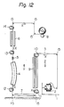
- Fig. 11 is a diagram illustrating one embodiment of the present false twisting apparatus and Fig. 12 is a diagram illustrating another embodiment of the present false twisting apparatus.
- reference numeral 1 represents a feed yarn creel on which feed yarn packages 2 are mounted. A feed yarn 23 in the form of multifilaments is taken out from the feed yarn package 2.
- Reference numeral 4 represents a false twisting heater for false-twisting the supplied yarn 3 in the heated state, and ordinarily, a hot plate or hot tube is used as the false twisting heater.
- a false twisting element 5 is disposed to give false twists to the supplied yarn 3.
- Reference numeral 6 represents a stabilizing heater for heat-setting the false twist-untwisted state in the supplied yarn 3, and ordinarily, a heater of the non-contact type is used as the stabilizing heater 6.
- this stabilizing heater 6 may be omitted.
- Reference numerals 7, 8 and 9 represent an operation passage, a winder and a heat-treating heater, respectively.
- the heat-treating heater 9 is arranged upstream of the false twisting heater 4 in the running passage of the yarn 3 indicated by arrow X between the false twisting heater 4 and the feed yarn creel 1 at a height substantially equal to the height of the feed yarn creel 1 so that the heat-treating heater 9 confronts the false twisting heater 4. If the heat-treating heater 9 is arranged so that the above-mentioned positional requirements are satisfied, important effects of the present invention are attained as described below.
- the heat-treating heater 9 is arranged so that it confronts the false twisting heater 4, the operation can be facilitated by the provision of the operation passage 7 arranged below and between the two heaters 4 and 9.
- the heat-treating heater 9 and the feed yarn creel 1 are located on the same side with respect to the operation passage 7. If the position of the heat-treating heater 9 is thus specified, a yarn cooling zone can be formed between the outlet of the heat-treating heater 9 and the inlet of the false twisting heater 4.
- a heater of the non-contact type is used as the heat-treating heater 9.
- the heater of the non-contact type there are preferably used, for example, a groove-shaped heater in which a yarn is passed through a groove of a heater plate without being contacted therewith, a hollow pipe-shaped heater in which a yarn is passed through the hollow portion of the heater with no contact with the heater wall and a box-shaped heater having a relatively large size, through which a plurality of yarns are passed with no contact with the heater wall.
- a groove-shaped heater in which a yarn is passed through a groove of a heater plate without being contacted therewith
- a hollow pipe-shaped heater in which a yarn is passed through the hollow portion of the heater with no contact with the heater wall
- a box-shaped heater having a relatively large size through which a plurality of yarns are passed with no contact with the heater wall.
- other heaters of the non-contact type may be used. Since the heat-treating heater 9 is of the non-contact type, the heating efficiency of the heat-treating heater 9 is low. Accordingly, it is preferred that the length
- Feed rollers 10, 11, 12, 13 and 14 are rotated at predetermined peripheral speeds to allow the feed yarn 3 to travel and to give a predetermined drawing or relaxation to the yarn in a present section.
- Guide pins 15 are disposed to allow the feed yarn 3 to travel along a predetermined course in co-operation with the feed rollers, while changing the running direction of the yarn 3.
- the heat-treating heater 9 and false twisting heater 4 are arranged to confront each other, for example, with the operation passage 7 being interposed therebetween, as shown in the drawings. Accordingly, air above the operation passage 7, which is a space interposed between the two heaters 9 and 4, is heated by the heat radiated from both the heaters to form a rising air current in the direction indicated by arrow Y. Therefore, a descending current of cold air flowing in the direction of arrow Z is present on the side of the feed yarn creel 1 on the back of the heat-treating heater 9 and on the back side of the false twisting heater 4.
- the feed yarn package 2 is not allowed to fall in contact with heated air but is rather cooled by cold air, and hence, an oil on the feed yarn is not evaporated and no change of the yarn quality is caused, with the result that at the subsequent false twisting step, formation of fluffs and occurrence of yarn breakage are minimized and a false-twisted yarn having excellent properties can be obtained.
- the heat-treating heater 9 is arranged to confront the false twisting heater 4 at the substantially same height, as shown in Fig. 12, the mist of the oil evaporated while the feed yarn 3 is passed through one heater does not adhere to the feed yarn 3 which is being passed through the other heater, and the feed yarn 3 stably travels in the state where an appropriate amount of the oil is uniformly applied to the feed yarn 3. Accordingly, a uniform false-twisted yarn free of tight spots, which is excellent in the dyeability, can be obtained according to the preferred embodiment shown in Fig. 12.
- the feed yarn 3 is sufficiently cooled by natural cooling while it travels from the heat-treating heater 9 to the false twisting heater 4, and there can be obtained a false-twisted yarn having an excellent dyeability.
- the dynamic mechanical loss tangent (tan 6) can be measured by using an apparatus for measuring the dynamic viscoelasticity, manufactured by Toyo Baldwin, Rheo-Vibron DDV-Ilc, at a frequency of 110 Hz in dry air at a temperature-elevating rate of 10°C/min.
- a peak temperature (T maxI of tan 6 and a peak value [(tan 6) ma ,.] of tan 5 are obtained from the tan 5-temperature curve.
- Typical instances of the tan o-temperature curve are shown in Fig. 13, in which (A) is a curve of a false-twisted polyester yarn prepared according to the present invention, (B) is a curve of a conventional drawn fiber, (C) is a curve of an undrawn fiber spun at a spinning speed of 1,500 m/min and (D) is a curve of a partially oriented fiber spun at a spinning speed of 3,000 m/min.
- the X-ray generator is operated at 30 KV and 80 mA.
- the diffraction intensity is recorded from 7° to 35° of 28 at a scanning speed of 1°/min, a chart speed of 10 mm/min, a time constant of 1 second, a divergent slit of 1/2°, a receiving slit of 0.3 mm and a scattering slit of 1/2°.
- the full scale deflection of the recorder is set so that the entire diffraction curve remains on the scale.
- a polyethylene terephthalate fiber has three major reflections on the equatorial line in the range of from 17° to 26° of 28 at faces of (100), (010) and (110).
- Fig. 15 is an example of the curve of the X-ray diffraction intensity of a polyethylene terephthalate fiber, in which (a) indicates a portion of the X-ray diffraction intensity attributed to the crystalline region and (b) indicates a portion of the X-ray diffraction intensity attributed to the amorphous region.
- a base line is established by drawing a straight line between 7° and 35° of 28 on the diffraction intensity curve.
- the crystalline portion (a) and the amorphous portion (b) are separated by drawing a straight line along the tail of the lower angle and the tail of the higher angle from the peak point positioned near the angle of 20° of 28.
- the X c value is represented by an area analysis method according to the following equation:
- the distribution of the mean refractive index, observed from the side face of a fiber can be determined.
- the refractive index of fibers is characterized by a refractive index n// to polarized light having an electric field vector in the direction parallel to the fiber axis and a refractive index n 1 to polarized light having an electric field vector in the direction perpendicular to the fiber axis.
- the fiber to be tested is immersed in a sealing medium being inert to fibers and having a refractive index (N) giving a deviation of the interference fringe in the range of 0.2 to 2.0 times the wavelength by using optically flat slide glass and cover glass.
- the fiber should be disposed so that the fiber axis is perpendicular to the optical axis of the interference microscope and the interference fringe.
- the pattern of the interference fringe is photographed and enlarged at about 1,500 magnifications for analysis.
- the optical pass difference R is represented by the following formula: wherein N is the refractive index of the sealing medium, n// or (n 1 ) is the refractive index between the points S' and S" on the periphery of the fiber, t is the thickness between the points S' and S",
- A is the wavelength of the radiation used
- D is the distance (corresponding to 1 A) between parallel interference fringes of the background
- d is the deviation of the interference fringe by the fiber.
- the distribution of the refractive index n// or n ⁇ of the fiber at each portion can be determined.
- X is 1 at the position on the periphery of the fiber but X is a value of 0 to 1 at the other position of the fiber.
- the mean birefringence index (An) is represented as
- reference numerals 31, 32 and 33 represent the fiber, the interference fringe by the sealing medium and the interference fringe by the fiber, respectively.
- the dyeability is evaluated by a dye up-take ratio.
- a sample is dyed with a disperse dye (Resolin Blue FBL, C.I. Disperse 56, supplied by Bayer AG, West Germany) at a dye concentration of 3% owf and a liquor ratio of 1 to 50 at 100°C. Further, 1 g/I of a dispersing agent (Disper TL) is added to the dyeing liquor and the pH value is adjusted to 6 by addition of acetic acid.
- a disperse dye Resolin Blue FBL, C.I. Disperse 56, supplied by Bayer AG, West Germany
- 1 g/I of a dispersing agent Dispersing agent
- the dyeing liquor is sampled and the amount of the dye left in the dyeing liquor is measured by the absorbance at 625 mp, and the amount of the dye taken up is calculated by subtracting the amount of the dye left in the dyeing liquor from the amount of the dye used for the dyeing operation.
- the dye up-take ratio (%) is calculated by dividing this amount of the dye taken up by the amount employed of the dye and multiplying the result by 100.
- the sample fiber is formed into a knitted fabric, and the fabric is scoured with 2 g/I of "Scourol FC-250" (supplied by Kao-Atlas) at 60°C for 20 minutes, dried and conditioned at a relative humidity of 65% and a temperature of 20°C for 24 hours, and the sample fabric is then tested.
- Scourol FC-250 supplied by Kao-Atlas
- the dye up-take ratio is 83%. If the dye up-take ratio of the sample is higher than 83%, it is judged that the dyeability of the fiber is good and the fiber can be dyed under normal pressure.
- the tenacity is measured by using a tensile testing machine ("Tensilon UTM-11-20" manufactured by Toyo Baldwin) at an initial length of 20 cm and a tensile velocity of 20 mm/min.
- the initial length of 20 cm employed is the length of the crimp elongated.
- the CD 5 . 0 value of a textured yarn from the false twisting step or draw-false twisting step is measured, and this value is designated as a.
- the textured yarn is immersed in boiling water at 100°C under a load of 0.01 g/d for 1 minute. Then, the yarn is naturally dried at a temperature of 20°C and a relative humidity of 60% in the free state without the load, and the CD 5 ., value is measured again. This value is designated as ⁇ .
- the crimp retention of the textured yarn is expressed by the following formula:
- the crimp retention is at least 65%, it is judged that the crimp retaining property is good.
- the easiness in the threading operation is qualitatively judged according to the three-staged method. If the easiness in the threading operation is comparable to that in case of a conventional false-twisted or drawn and false-twisted polyester yarn, the sample is indicated by mark "A". If the sample is fused by contact with the tube heater or broken or fluffs are formed and the threading operation becomes very difficult, the sample is indicated by mark "B”. A sample having a threading property intermediate between those of the above-mentioned two samples is indicated by mark "C".
- 1 kg of a false-twisted or drawn and false-twisted yarn is wound up in a parallel cheese form, and the number of broken filaments present on both the end faces of the cheese is counted and the counted number is designated as the number of fluffs. Accordingly, the unit is expressed by fluffs/kg. If the number of fluffs is not smaller than 5.0 fluffs/kg, troubles are readily caused at the subsequent knitting or weaving step. Therefore, it is indispensable that the fluff number should be smaller than 5.0 fluffs/kg.
- a standard yarn and sample yarns are knitted separately by using a one feeder knitting machine.
- the knitted fabrics are scoured under the same conditions as used in the test of dyeability (item D). After scouring, the standard fabric and the sample fabrics are dyed simultaneously in the same dyeing liquor.
- the dyeing conditions are as follows.
- the dyed fabrics are dried and then the colour differences (tolerance indexes) between the standard fabric and the respective samples fabrics are measured.
- the yield (Y) of acceptable dyeing level is calculated by the following equation. K. Evenness of dyeing
- Polyethylene terephthalate having an intrinsic viscosity [ ⁇ 1 of 0.68 dl/g as measured at 35°C in a 2/1 mixed solvent of phenol/tetrachloroethane was spun under conditions shown in Table 1 by using the spinning and winding apparatus shown in Fig. 1 to obtain a polyester filament yarn shown in Table 1.
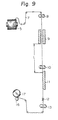
- the yarns A, B and C shown in Table 1 were treated by using the apparatus shown in Fig. 9 and Table 2 under conditions shown in Table 3.
- the treating temperature was room temperature, 20°C.
- Example 2 the yarn B of Example 1 was treated under conditions shown in Tables 2 and 3 by using the apparatus shown in Fig. 9.
- the cooling length L was 1.6 m
- the cooling time A was 0.64 second
- the cooling conditions were as shown in Table 5.
- Example 7 the yarn B of Example 1 was treated under conditions shown in Tables 2 and 3 by using the apparatus shown in Fig. 9.
- the cooling conditions adopted were as shown in Table 7.
- Copolymerization was carried out by substituting a part of terephthalic acid of ethylene terephthalate by isophthalic acid to obtain four kinds of polymers having isophthalic acid contents of 3, 6, 12 and 18% by weight, respectively. These polymers were independently melt-spun at a spinning speed of 5,000 m/min by using the spinning apparatus shown in Fig. 1 to obtain 4 kinds of 75 d/36 f as-spun yarns. The An values of the respective yarns are shown in Table 9.
- Polyethylene terephthalate having an intrinsic viscosity [ ⁇ ] of 0.64 dl/g was melt-extruded from a spinneret having 32 holes 0.35 mm in diameter at a spinning temperature of 298°C, and the spun yarn was cooled to be solidified by an air current maintained at 25°C and supplied in the direction parallel to the running direction of the yarn. Then, an oiling agent was applied to the yarn and the yarn was wound at a speed of 3,000 to 6,000 m/min.
- the obtained polyester multifilament yarn composed of 32 filaments having properties shown in Table 10 was treated by using an apparatus shown in Fig. 7 and Table 11 under conditions shown in Table 12. The obtained results are shown in Table 13. During the false twisting treatment, twists given to the yarn were propagated upstream to the heat-treating heater, and the twists shown in Table 12 were given to the yarn at the heat treatment.
- Polyethylene terephthalate having an intrinsic viscosity [ ⁇ ] of 0.65 dl/g was extruded at a spinning temperature of 300°C from a spinneret having 36 Y-shaped orifices, and the spun yarn was cooled and solidified by cold air maintained at 18°C and supplied in the direction parallel to the running direction of the yarn.
- An oiling agent was applied to the yarn, and the yarn was wound at a speed of 5,500 m/min to obtain a yarn comprising single filaments having a triangular section and having a total denier of 50 deniers.
- the yarn was subjected to heat treatment, cooling and false twisting in the apparatus shown in Fig. 9.
- the heat treatment temperature was 248°C
- the heat treatment time was 0.84 second
- cooling was carried out for 0.9 second in an atmosphere maintained at 23°C.
- the false twisting heater temperature was 210°C
- the twist number was 3,800 t/m
- the draw ratio at the false twisting treatment was 0%.
- the tenacity of the obtained false-twisted yarn was 3.7 g/d and the dye up-take ratio was 87%. Thus, it was found that the false-twisted yarn had a practically sufficient tenacity and could be dyed under normal pressure.
- Polyethylene terephthalate having an intrinsic viscosity [ ⁇ ] of 0.67 dl/g was extruded at a spinning temperature of 302°C through a spinneret having 36 orifices 0.35 mm in inner diameter, and the spun yarn was cooled and solidified by cold air maintained at 20°C and supplied in the direction parallel to the running direction of the yarn.
- Five kinds of 75 d/36 f multifilament yarns were prepared by adopting spinning speeds of 2,000, 3,000, 4,000, 5,000 and 6,000 m/min.
- the An values of the respective yarns are shown in Table 14. These yarns were subjected to heat treatment, cooling and false twisting or draw-false twisting under conditions shown in Table 14 by using the apparatus shown in Fig. 9.
- the tenacities and dye up-take ratios of the obtained false-twisted yarns are shown in Table 14.
- the tenacity was higher than 3 g/d if the elongation rate at the heat treatment was 35%, but if the elongation rate at the heat treatment was 0%, the tenacity was less than 3 g/d.
- the tenacities and dye up-take ratios of the obtained false-twisted yarns are shown in Table 15.
- the tenacity and dye up-take ratio of the obtained false-twisted yarn are shown in Table 16.
- Polyethylene terephthalate having an intrinsic viscosity of 0.635 dl/g as measured at 35°C in a 2/1 mixed solvent of phenol/tetrachloroethane was melt-extruded from a spinneret having 36 holes 0.35 mm in diameter at a spinning temperature of 303°C, and the spun yarn was cooled to be solidified by an air current maintained at 20°C and fed in the direction parallel to the running direction of the yarn. An oiling agent was applied to the yarn and the yarn was wound. Three sets of the extrusion rate and winding speed shown in Table 17 wre adopted, and three kinds of 75 d/36 f as-spun yarns X, Y and Z were obtained.
- the false twisting apparatus described in the present invention is excellent over the conventional heat-treating heater-provided false twisting apparatus because formation of fluffs and occurrence of yarn breakage are remarkably reduced and good false twisting properties can be obtained, and the false-twisted yarn obtained by using the false twisting apparatus described in the present invention is highly improved in the tight spot property, evenness of dyeing, yield of acceptable dyeing level and dyeability.
- the as-spun yarn Y of Example 10 was subjected to the partially molten-false twisting by using the apparatus No. 1 or No. 2 used in Example 10 to obtain a linen-like partially molten-false-twisted yarn. Treating conditions were as follows.
- the false twisting apparatus described in the present invention is advantageous over the conventional heat-treating heater-provided false twisting apparatus in that formation of fluffs and occurrence of yarn breakage are remarkably reduced, the adaptability to the false twisting treatment is improved and the dye up-take ratio of the obtained yarn is enhanced.
- Polyethylene terephthalate having an intrinsic viscosity of 0.65 dl/g was melt-extruded from a spinneret having 24 orifices, each 0.23 mm in diameter at a spinning temperature of 300°C.
- the yarn extruded was cooled and solidified with a stream of air at 20°C supplied in parallel to the direction of the running yarn, and then the yarn was wound at a winding speed of 4,500 m/min to give multifilaments of 50 d/24 f by using the spinning apparatus shown in Fig. 1.
- a mean birefringence index An of the yarn was 71 x10 -3 .
- the wound yarn was subjected to heat treatment for 0.8 second at an elongation ratio of 0% by passing through a heat treating heater 9 as shown in Fig. 9, which was placed in an atmosphere of mixed gas containing 80 mol% of super heated steam and 20 mol% of air heated at 235°C. Subsequently the yarn was naturally cooled for 1.2 second in an atmosphere maintained at 25°C, and then the yarn was false-twisted at a false twisting temperature of 212°C at a draw ratio of 7% and a twisting number of 3,900 t/m.
- the tenacity and dye up-take ratio of the false-twisted yarn are 3.3 g/d and 87%, respectivelv.
Landscapes
- Engineering & Computer Science (AREA)
- Mechanical Engineering (AREA)
- Textile Engineering (AREA)
- Yarns And Mechanical Finishing Of Yarns Or Ropes (AREA)
- Artificial Filaments (AREA)
Description
- This invention relates to a process for producing a false-twisted polyester yarn wherein an as-spun polyester yarn is subjected in succession to heat treatment, cooling and then false twisting or draw-false twisting.
- Polyester fibers are excellent in mechanical and thermal properties and they have been used in not only the field of clothing articles but also the field of industrial materials. However, the polyester fibers are poor in the dyeability, and especially, fibers composed of a polyethylene terephthalate homopolymer are difficult to dye and they can be dyed only under a high pressure at a high temperature such as about 130°C.
- As means for improving this poor dyeability of polyester fibers, there has been proposed a method in which a carrier is added to a dyeing liquor. However, this method has problems in that the carrier is irritating, the operation environment is contaminated and worsened, disposal of the waste dyeing liquor is difficult and the color fastness is degraded.
- It is known that the dyeability of polyester fibers can be improved by copolymerizing polyethylene terephthalate with isophthalic acid having a metal sulfonate group or polyether. However, these modified polyester fibers still cannot be dyed under normal pressure.
- These defects of the conventional polyester fibers are observed in not only flat yarns but also false-twisted yarns.
- FR-A-2 193 893 teaches a process of making a bulky yarn which comprises drawing an unsubstituted or partially substituted yarn and false-twist-crimping the drawn yarn by using a frictional twisting apparatus while sliding between the yarn and the frictional surface of the apparatus is avoided.
- FR-A-2 208 999 teaches a process for making a textured yarn by the simultaneous false-twisting and stretching of an unstretched or incompletely stretched yarn. In this process, the unstretched or incompletely stretched yarn is delivered at a high velocity of 200 to 600 m/min and drawn at a temperature between T=glass transition temperature and T+50°C.
- FR-A-2 129 710 teaches the false-twisting of yarn wherein the yarn is drawn at a temperature of 50 to 150°C.
- CH-A-530 487 teaches a continuous process wherein a polyester yarn is drawn at a temperature of 90 to 170°C, the drawn yarn is cooled to room temperature, and the cooled yarn is subjected to false-twisting and simultaneously heat-setting at a temperature of 160°C to 230°C.
- It is a primary object of the present invention to provide a process and an apparatus for producing a false-twisted polyester yarn having a good dyeability, particularly being capable of being dyed under normal pressure to give an excellent color fastness and retaining excellent mechanical and thermal properties of polyester fibers, at a high efficiency and with a good operation adaptability.
- Other objects and advantages of the present invention will be apparent from the following description.
- In accordance with the fundamental aspect of the present invention, there is provided a process for producing a false-twisted polyester yarn from a yarn consisting of an as-spun polyester fiber having a mean birefringence index (An) of at least 15x10-3 but less than 150X10-', which has been spun at a spinning speed of at least 2,500 m/min but less than 7,000 m/min, this process comprises continuously subjecting said yarn to (1) a preliminary heat treatment carried out in an atmosphere maintained at a temperature of 190°C to 300°C, (2) natural cooling conducted at a temperature of 20°C±15°C for the period of A satisfying the following formula:

- In accordance with the present invention, there is described a false twisting apparatus which comprises a feed yarn creel, a false twisting heater and an optional stabilizing heater, a false twisting element and a winder, wherein a heat-treating heater of the non-contact type is arranged upstream of the false twisting heater and between the false twisting heater and the feed yarn creel, at a height substantially equal to the height of the feed yarn creel so that the heat-treating heater confronts the false twisting heater.
- Fig. 1 is a diagram illustrating one embodiment of the spinning and winding device for a polyester yarn;
- Fig. 2 is a graph illustrating the relationship between the spinning speed (m/min) and the degree of crystallinity (xc%) of the yarn before the heat treatment;
- Fig. 3 is a graph illustrating the relationship between the spinning speed (m/min) and the mean birefringence index (An) of the yarn before the heat treatment;
- Figs. 4 and 5 are graphs illustrating the relationship between the heat treatment time and the degree of crystallinity (xc%) of a polyethylene terephthalate fiber and the relationship between the heat treatment time and (tan o)max and T max (°C), respectively, which are observed when a polyethylene terephthalate fiber spun at a spinning speed of 3,500 m/min is heat-treated in air maintained at 260°C at an elongation ratio of 12%, each numerical value in Fig. 5 representing the heat treatment time (second);
- Fig. 6 is a diagram illustrating another embodiment of the process of the present invention in which a twisted yarn is treated by using a heat-treating heater of the contact type;
- Fig. 7 is a diagram showing a modified embodiment of Fig. 6 where the treatment of a twisted yarn is carried out by using a heat-treating heater of the non-contact type;
- Fig. 8 is a diagram illustrating an embodiment of the process of the present invention, in which a crimp-setting treatment by a stabilizing heater is carried out subsequently to the false twisting or draw-false twisting treatment;
- Fig. 9 is a diagram showing another embodiment of the process of the present invention, in which the yarn is heat-treated by a slit or hollow tubular heat-treating heater of the non-contact type.
- Fig. 10 is a diagram illustrating one example of the conventional false twisting apparatus provided with a pre-heating heater;
- Figs. 11 and 12 are diagrams showing embodiments of the apparatus used in the present invention in which heat treatment, cooling and false twisting or draw-false twisting are carried out in a continuous manner;
- Fig. 13 shows a tan 6-temperature curve of a polyester fiber, in which the logarithms of tan are plotted on the ordinate and the temperatures (°C) are plotted on the abscissa and in which (A) shows the false-twisted yarn obtained according to the process of the present invention, (B) shows the drawn yarn prepared according to the conventional process, (C) shows the as-spun yarn (i.e., undrawn yarn) spun at a spinning speed of 1,500 m/min and (D) shows the tan 6-temperature curve of the as-spun yarn (P.O.Y.) spun at a spinning speed of 3,000 m/min;
- Fig. 14 is an example of an interference fringe pattern used for measuring the distribution of the refractive index (n"" or n1) in the direction of the radius of the cross-section of a polyester fiber, in which (a) is a view showing the cross-section and (b) is a view showing an interference fringe pattern; and
- Fig. 15 is an example of the X-ray diffraction-intensity curve of a polyester fiber, in which (a) represents the crystalline region and (b) represents the amorphous region.
- The "polyester fiber" used in the present invention means not only a fiber made of a polyethylene terephthalate homopolymer but also a fiber made of a copolyester comprising ethylene terephthalate as the main repeating unit component and up to 15% by weight of a third copolymerized component. As the third component, at least one member selected from isophthalic acid, adipic acid, oxalic acid, trimellitic acid, pyromellitic acid, p-hydroxybenzoic acid, 2,6 - naphthalene - dicarboxylic acid, 5 - sodium - sulfoisophthalic acid, sebacic acid, azelaic acid and 2,5 - dimethyl - terephthalic acid may be used instead of a part of terephthalic acid, and at least one member selected from diethylene glycol, propylene glycol, 1,4-butanediol, 1,4-dihydroxymethylcyclohexane and polyoxyethylene glycol may be used instead of a part of ethylene glycol.
- Furthermore, a fiber of a polymer such as mentioned above used in the present invention may comprise additives customarily added to synthetic fibers, such as a delustering agent, an antistatic agent and a stabilizer.
- The dyeability of a fiber of a polyester comprising main repeating units of ethylene terephthalate and a third copolymerized component as mentioned above is improved over the dyeability of a fiber of a homopolyester of ethylene terephthalate, and the degree of the improvement of the dyeability varies according to the kind of the copolymerized component and the weight proportion thereof. More specifically, of components to be copolymerized instead of a part of terephthalic acid, an acid free of an aromatic ring, such as adipic acid or sebacic acid, gives a higher degree of the improvement of the dyeability than an acid containing an aromatic ring, and of acids containing an aromatic ring, an acid having a substituent as a side chain on the aromatic ring gives a higher degree of the improvement of the dyeability than an aromatic ring-containing acid free of such a substituent. Of components to be copolymerized instead of a part of ethylene glycol, a component having a higher molecular weight, such as polyoxyethylene glycol, gives a higher degree of the improvement of the dyeability than a component having a lower molecular weight, such as diethylene glycol. Ordinarily, the larger the weight proportion of the third component, the higher the degree of the improvement of the dyeability.
- In the case where the dyeability of a polyester fiber is improved by copolymerization of a third component such as mentioned above, with increase of the proportion of the third component, spinning becomes difficult and the manufacturing cost is increased. Furthermore, the thermal and mechanical properties of the obtained copolyester fiber are lower than those of a fiber of a polyethylene terephthalate homopolymer. Moreover, if the weight proportion of the third copolymerized component exceeds 15%, the melting point is drastically lowered. For example, when at least 16% by weight of isophthalic acid is copolymerized as a part of terephthalic acid and the formed copolyester is spun and drawn according to customary procedures, the melting point of the resulting polyester fiber is 230°C or lower, and the heat resistance is drastically degraded with reduction of the mechanical properties. Accordingly, in the present invention, from the viewpoint of the adaptability to the heat treatment or the false twisting or draw-false twisting treatment, the weight proportion of the third copolymerized component should be up to 15%, preferably up to 5%, more preferably 0%. Namely, a polyethylene terephthalate homopolymer is most preferred.
- The polyester yarn used in the present invention is a multiflament yarn consisting of at least two single filaments. The size of the single filament is 0.01 to 10 deniers and the cross-section of the single filament may be either circular or non-circular.
- An as-spun polyester yarn having a An value of at least 15x10-3 but less than 150x10-3, which is used in the present invention, may be obtained by performing spinning and winding at a spinning speed of at least 2,500 m/min but less than 7,000 m/min, for example, in an apparatus as shown in Fig. 1. In Fig. 1,
reference numerals - By the term "spinning speed" is meant a surface speed of a
winding friction roll 6 when the spinning-winding operation is carried out according to the apparatus shown in Fig. 1. - The spinning operation conducted at a spinning speed of 7,000 m/min or higher is not advantageous from the industrial viewpoint because the equipment cost of the winding device is increased and close attention should be paid to the control and maintenance of various conditions at the spinning step. At the present, therefore, spinning speeds of less than 7,000 m/min are advantageous.
- The as-spun polyester yarn having a An value of at least 15x10-3 but less than 150x10-3, which is obtained by the above-mentioned spinning operation, is subjected to the heat treatment without passage through any special drawing step prior to the heat treatment.
- The heat treatment of the present invention is accomplished, for example, by heat-treating the polyester yarn having the above-mentioned An value in a heated tubular heater or slit heater without being contacted with the surface of the heater; passing the yarn through heated air or super-heated steam or allowing the yarn to travel while contacting it with a heated metal plate.
- When the yarn is passed through the heated tubular or slit heater, the temperature of the heater is adjusted to 190 to 300°C. An optimum heat treatment temperature varies depending upon such factors as the An value of the fiber, the composition of the copolymer, the heat treatment time, the fiber elongation ratio, the fineness of the single filament and the fineness of the yarn.
- Fig. 3 shows the relationship between the spinning speed (m/min) and the An value of a 35-d/7-f multi-filament yarn having a filament section of a circular shape, which is obtained by spinning a polyethylene terephthalate homopolymer having an intrinsic viscosity of 0.63 dl/g as measured at 35°C in a 2/1 mixed solvent of phenol/tetrachloroethane at various spinning speeds by using the spinning apparatus shown in Fig. 1. From Fig. 3, it is seen that the spinning speed providing a An value of 50x10-3 is about 4,000 m/min and the spinning speed providing a An value of 15x10-3 is about 2,500 m/min. Fig. 2 shows the relationship between the spinning speed (m/min) and the degree of crystallinity Xc (%) determined from the X-ray diffraction curve, which is observed when spinning is carried out in the same manner as described above. From Fig. 2, it is seen that a polyethylene terephthalate fiber spun at a spinning speed of at least about 4,000 m/min, that is, a polyethylene terephthalate fiber having a Δn value of at least 50x 10-3, has a Xc value of at least 50%, and the structure of the fiber is substantially completed. However, a polyethylene terephthalate fiber spun at a spinning speed of at least about 2,500 but less than about 4,000 m/min may be regarded as an incomplete fiber in which the structure of the fiber is being formed. Accordingly, the polyester fiber having a An value of at least 15x10-3 but less than 50x10-3, that is, the polyester fiber spun at a spinning speed of at least about 2,500 but less than about 4,000 m/min, is different from the polyester fiber having a Δn value of at least 50x 10-3, that is, the polyester fiber spun at a spinning speed of at least 4,000 m/min, and should be drawn at the heat treatment. A polyester fiber having a An value of less than 15x10-3, that is, a polyester fiber spun at a spinning speed of less than about 2,500 m/min, is composed substantially of an amorphous portion and the degree of orientation of the molecule chain is low. Therefore, if this polyester fiber is subjected to the heat treatment according to the present invention, partial fusion is caused and the tenacity and elongation are extremely low.
- Since a polyethylene terephthalate homopolymer fiber having a An value of at least 50x10-3 has a substantially completed fiber structure, when the fiber is passed through a tubular or slit heater maintained at a temperature of 220 to 300°C over a period of 0.4 to 2 seconds while adjusting the fiber elongation ratio in the range of from -10% to +4% during the heat treatment, the heat-treated fiber comes to have an increased degree of crystallinity and an increased refractive index. Namely, the fiber structure is more completed. Moreover, the structure of the amorphous region dominating the dyeability of the fiber is relaxed so that the fiber can be dyed even under normal pressure with a disperse dye. The dynamic loss tangent (tan δ)-temperature characteristic is suitable for defining the structure of the amorphous portion.
- There have been reported several studies made on the relationship between the dyeability of a fiber with a disperse dye and the viscoelasticity of the fiber [for example, K. Kamide and S. Manabe, "Fine Structure of Amorphous Region of Fiber Revealed by Dynamic Dispersion", Sen-i Gakkaishi, 34, page 70 (1978)]. According to these studies, it is generally considered that the larger the value of tan δ relating to a mechanical absorption due to the microbrownian movement of the main chain and the lower the temperature position of the mechanical absorption, the more improved the dyeability. According to our study, it has been found that parameters of a polyester fiber before the false twisting treatment or the draw-false twisting treatment, which are preferred from the viewpoint of the fine structure, are as follows. Namely, the peak value of tan δ, i.e., (tan δ)max, in the tan δ-temperature curve is at least 0.10, the temperature Tmax at which tan δ shows a peak is not higher than 115°C, the value of tan δ at 220°C, i.e., tan δ220, is not more than 0.055, the value of Xc is at least 50% and the value of An is at least 35x10-3. If a fiber having such parameters is subjected to the false twisting treatment or draw-false twisting treatment, a fiber dyeable under normal pressure can be obtained. An as-spun polyester fiber spun at a spinning speed of less than about 4,500 m/min have the (tan δ)mx and T max values falling within the above-mentioned ranges, but tan δ220 exceeds 0.055 and both or either of Xc and An is less than the above lower limit and the mechanical properties are low and the stability against heat is insufficient. If this polyester fiber is subjected to the false twisting treatment or draw-false twisting treatment, the structure is greatly changed by influences of heat received during the treatment, (tan 5)max becomes less than 0.14 and Tmax becomes higher than 130°C, and the false-twisted yarn cannot be dyed under normal pressure.
- The polyester fiber heat-treated according to the process of the present invention is characterized as possessing a (tan δ)max value of at least 0.10, a Tmax value not higher than 115°C, a tan δ220 value not more than 0.055, a Xc value of at least 50% and a An value of at least 35x10-3, and, if cooling described below is performed, even after the false twisting treatment or draw-false twisting treatment, the polyester fiber can be dyed under normal pressure.
- The conditions of the heat treatment of an as-spun fiber having a An value of at least 50x10-3 but less than 150x10-3 for obtaining an easily dyeable polyethylene terephthalate fiber having the above-mentioned fine structure are as described hereinbefore, when the fiber is passed through a tubular or slit heater. In the process of the present invention in which the cooling treatment and the false twisting treatment or draw-false twisting treatment is carried out successively after the heat treatment, from the viewpoints of the cooling time, the time required for the false twisting or draw-false twisting treatment, the capacity of the apparatus and the properties and quality of the obtained false-twisting yarn, it is preferred that the heater temperature be 230 to 270°C, more preferably 240 to 260°C, the heat treatment time be 0.4 to 1.5 seconds, more preferably 0.6 to 1.3 seconds, and the elongation ratio be -8 to +3%, more preferably -6 to +1%.
- When the fiber to be heat-treated is a copolyester fiber, a temperature lower than the above-mentioned heat treatment temperature by the difference between the melting point of the polyethylene terephthalate fiber and the melting point of the copolyester fiber is adopted for the heat treatment. For example, the melting point of a fiber obtained by copolymerizing polyethylene terephthalate with 5% by weight of isophthalic acid and spinning the copolyester at a spinning speed of 6,000 m/min is 247°C, which is lower by about 10°C than the melting point of a fiber of a polyethylene terephthalate homopolymer. Accordingly, a temperature suitably adopted for the heat treatment in the tubular heater is 230 to 250°C. The melting point of a fiber obtained by copolymerizing polyethylene terephthalate with 12% by weight of isophthalic acid and spinning the copolyester in the same manner as described above is 232°C, which is lower by about 25°C than the melting point of the fiber of a polyethylene terephthalate homopolymer, and a temperature suitable for the heat treatment of the fiber of this copolyester is 215 to 235°C. As is seen from this reduction of the melting point, copolyesters as described above are sensitive to heat, and therefore, in the heat treatment of fibers of these copolyesters, close attention should be paid to the control of the heat treatment temperature. The treatment time and elongation ratio to be adopted for the heat treatment of copolyester fibers may be the same as those adopted for the heat treatment of fibers of a polyethylene terephthalate homopolymer.
- The structure of an ordinary as-spun polyester fiber having a An value of at least 15x10-3 but less than 50x10-3 and consisting of single filaments having a circular section and a size of at least 1 denier is not completed and the Xc value is low. In the present invention, such a fiber should be drawn by 5 to 200% at the heat treatment. If the heat treatment is carried out without effecting this drawing, crystals are not sufficiently grown or developed, and therefore, the fiber is partially fused and the mechanical properties are drastically degraded.
- However, if the above-mentioned fiber is heat-treated while drawing it by 5 to 200%, fusion of the fiber is not caused, and there is obtained a fiber to be preferably subjected to the false twisting treatment or draw-false twisting treatment in the present invention, in which the (tan 5)max value is at least 0.10, the Tmax value is less than 115°C, the tan 6220 value is less than 0.055, the Xc value is at least 50% and the An value is at least 50x10-3.
- The temperature adopted for heat-treating a polyester fiber spun at a spinning speed of at least 2,500 m/min but less than 4,000 m/min may be the same as the temperature to be adopted for heat-treating a polyethylene terephthalate homopolymer fiber spun at a spinning speed of at least 4,500 m/min. However, if the heat treatment is carried out in a tubular heater or in heated air, it is preferred that the heat treatment temperature be in the range of 190 to 270°C, more preferably 200 to 260°C.
- Fig. 4 illustrates the relationship between the heat treatment time (second) and the Xc value (%) of the fiber, which is observed when a polyethylene terephthalate homopolymer fiber spun at a spinning speed of 3,500 m/min is heat-treated in air heated at 260°C under an elongation ratio of 12%. From Fig. 4, it is seen that the Xc value is increased as the treatment time is prolonged and if the heat treatment time is 0.2 second, the Xc value is substantially equal to the Xc value of the fiber spun at a spinning speed of 4,000 m/min, that is, 50%. It also is seen that the Xc value is gradually increased with prolongation of the treatment time and the Xc value is 72% if the treatment time is 0.77 second. Fig. 5 illustrates the relationship of the treatment time to (tan δ)max and Tmax values, which is observed when the above-mentioned fiber is heat-treated in the same manner as described above. The numerical values in Fig. 5 represent the heat treatment time (seconds). From Fig. 5, it is seen that with prolongation of the treatment time, (tan 8)max decreases but T max increases, and that if the treatment time is 0.2 to 0.3 second or longer, (tan o)max changes only to a minor extent but Tmax decreases. Namely, the heat treatment time region of up to 0.2-0.3 second is the region causing the structural change conventionally considered to be due to the heat treatment, that is, the region where the structure is made dense by the heat treatment. If the heat treatment time is further prolonged beyond the above region, crystals are developed but the amorphous portion is relaxed. This phenomenon is one discovered for the first time by us. Accordingly, in case of a polyester yarn spun at a spinning speed of at least 2,500 m/min but less than 4,000 m/min, it is necessary that the heat treatment time should be longer by at least 0.2 second than the heat treatment time for the polyester yarn spun at a spinning speed of at least 4,000 m/min, and thus, it is preferred that the polyester yarn be heat-treated for 0.4 to 2.0 seconds.
- In case of a copolyester yarn spun at a spinning speed of at least 2,500 m/min but less than 4,000 m/min, it is preferred that the heat treatment temperature may be lowered according to the proportion of the copolymerized component as described above with respect to the polyester yarn spun at a spinning speed of at least 4,000 m/min.
- Incidentally, the tan 6-temperature characteristics and the methods for measuring Xc and An will be described hereinafter.
- The foregoing heat treatment conditions are those for an ordinary polyester fiber in which the section of the filament has a circular shape and the size of the single filament is at least 1 denier. In case of a polyester fiber having a non-circular section such as a triangular or pentagonal section or a polyester fiber having a circular section but a size smaller than 1 denier, since the outer periphery of the fiber per unit sectional area is larger than that of the above-mentioned ordinary fiber and the influence of heat on the fiber is increased, it is permissible that the heat treatment temperature may be lowered by about 5 to about 10°C or the treatment time may be shortened by 0.1 to 0.2 second.
- In the process of the present invention, the heat treatment may also be carried out in super-heated steam or a mixed atmosphere of super-heated steam and hot air. In this case, the heat treatment time and the fiber elongation ratio during the heat treatment are the same as in case of the heat treatment conducted in the tubular or slit heater or heated air, but it is preferred that the heat treatment temperature be selected within the range of from (230―50Z)°C to (29050Z)°C in which Z stands for the mole fraction of super-heated steam in the heat-treating medium. Since steam has a larger heat capacity than that of air and exerts a higher heat-treating effect on the fiber, even if the heat treatment temperature is lower than that adopted when the heat-treating medium consists of air alone, a satisfactory heat-treating effect can be attained.
- In the process of the present invention, the as-spun polyester filament yarn having a An value of at least 15x10-3 but less than 150x10-3 may be heat-treated in the twisted state. In this case, it is preferred that the twist number be at least 3% of the twist number at the false twisting treatment or draw-false twisting treatment. The twist number T at the false twisting treatment or draw-false twisting treatment is 80 to 120% of

- As the means for twisting the yarn in this embodiment, there may be adopted a method in which the yarn is twisted before the heat treatment, but, when the false twisting treatment or draw-false twisting treatment is conducted successively after the heat treatment and cooling as in the present invention, there may preferably be adopted a manner wherein twists given by the false twisting are extended to the heat treatment zone.
- Figs. 6 and 7 illustrate embodiments in which the process of the present invention is carried out while twists given at the draw-false twisting step are extended to the heat treatment zone.
- Referring to Fig. 6, a travelling
yarn 7 unwound from awound yarn package 5 is passed through a feed roller (R1) 8 and through a heat-treatingheater 9 provided with a metal plate while being contacted therewith. When theyarn 7 is passed through the heat-treatingheater 9, twists propagated from afalse twisting element 14 are given to theyarn 7. After theyarn 7 is heated in the heat-treatingheater 9 in the twisted state, theyarn 7 is cooled by the atmosphere in the room and is guided into afalse twisting heater 13 through a twist stop guide 11. If this cooling treatment is not effected and thetwist stop guide 10 is not disposed, the drawing tension is extended into the heat-treatingheater 9. In thefalse twisting heater 13, the yarn is heated to a temperature higher than the glass transition point to initiate drawing. The point at which drawing is initiated is thedrawing point 12. After passage through thefalse twisting heater 13, the yarn is cooled again by the atmosphere in the room, and just after passage through thefalse twisting element 14, the yarn is untwisted and is then wound through adelivery roller 15 to form apackage 17 of the drawn and false-twisted yarn. In Fig. 6,reference numeral 16 represents a winding friction roller (R3). - Fig. 7 is a diagram illustrating another embodiment of the process of the present invention. The apparatus shown in Fig. 7 is the same as the apparatus shown in Fig. 6 except that the heat-treating
heater 9 is of the non-contact heating type. - In the case where the heat treatment is carried out in the twisted state, the heat treatment temperature and drawing ratio are the same as those adopted in the heat treatment conducted in heated air. If the yarn is contacted with the heater surface, the heat treatment time may be shortened by about 0.2 second as compared with the heat-treatment time required when the fiber is not contacted with the heater surface.
- It is only when the polyester yarn is passed through the drawing step after spinning thatthe An value of the polyester fiber exceeds 150x10-a, and any as-spun polyester yarn cannot have a An value exceeding 150x10-3. More specifically, as shown in Fig. 3, in case of the as-spun yarn, the An value is at a peak when the spinning speed is about 7,000 m/min and the peak An value is about 120x10-3. In the case where the filament denier is less than 1 denier, since the draft ratio is increased at the spinning step, even an as-spun yarn has a An value larger than that shown in Fig. 3 but the largest value is less than 150x10-3.
- It is very difficult to prepare an easily-dyeable false-twisted polyester yarn from a polyester fiber having a An value of at least 150x10-a, that is, a polyester fiber which has been drawn after the spinning step, according to a process similar to that of the present invention. In the fiber which has been drawn after the spinning step, the fine structure thereof, especially the structure of the amorphous region, is very dense and compact, and ordinarily, as shown in Fig. 13, the (tan 8)max value is about 0.1 and the Tmax value is at least 130°C. When it is intended to improve the dyeability of a spun and drawn polyester yarn having a An value of at least 150x10-3 by the heat treatment, it is necessary to relax the yarn by about 50% at the heat treatment, and in this case, even if the dyeability is improved, the mechanical properties are low and, for example, the tenacity is less than 2.5 g/d. Moreover, uneven dyeing is readily caused in the longitudinal direction of the yarn. Accordingly, it is practically impossible to prepare an easily-dyeable false-twisted polyester yarn from a polyester fiber having a An value of at least 150x10-3 according to the process of the present invention.
- In the present invention, it is indispensable that the heat-treated polyester yarn be cooled continuously after the heat treatment. By the term "continuously" used in the present invention, it is meant that after one stpe has been completed, a yarn is continuously transferred to the subsequent step without winding of the yarn, i.e., without interruption of the yarn travelling. Namely, the yarn which has been heat-treated in the above-mentioned manner is transferred to the cooling step without winding of the yarn.
- Either natural cooling or forced cooling may be adopted for cooling the heat-treated yarn.
- By the term "natural cooling", it is meant that the yarn is naturally cooled in the following manner. Ordinarily, the process of the present invention is carried out according to embodiments illustrated in Figs. 6, 7, 8 and 9. In the embodiment illustrated in Figs. 8 and 9, the
yarn 7 travels in the room temperature atmosphere during the passage of from the slit heater 11 to the false twisting heater 11. In this embodiment, by the term "natural cooling", it is meant that theyarn 7 is cooled in the room temperature atmosphre while it travels from the outlet of theslit heater 9 to the inlet of thefalse twisting heater 13. Similarly, in the embodiment illustrated in Figs. 6 and 7, theyarn 7 travels in the room temperature atmosphere during the passage of from theheater 9 to thefalse twisting heater 13. In this embodiment, by the term "natural cooling", it meant that theyarn 7 is cooled while it travels from the outlet of theslit heater 9 to the inlet of thefalse twisting heater 13. - Adoption of natural cooling is advantageous in that a cooling device need not be disposed and the deviation of the quality among lots can be reduced. In case of natural cooling, the cooling time (A) is important, and a good dyeability can always be attained if natural cooling is carried out so that the cooling time (A) satisfies the following requirement:
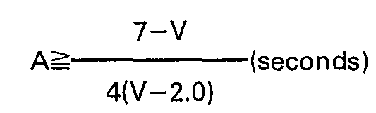
- By the term "cooling time (A)" used herein is meant a time required for the yarn to travel from the outlet of the heat-treating heater to the inlet of the false twisting heater.
- The reason why it is part of the invention that the cooling time (A) satisfies the above requirement is as follows. As pointed out hereinbefore, in an as-spun polyester yarn having a An value of at least 15x 10-1 but less than 50x10-3, that is, a polyester yarn spun at a spinning speed of at least about 2,500 m/min but less than about 4,000 m/min, the Xc value is small and the structure of the fiber is incomplete, and the yarn should be drawn in the heat treatment step. When the yarn is drawn in the heat treatment step, if the yarn is subjected to the false twisting treatment or draw-false twisting treatment after the heat treatment without performing cooling, especially in case of a small elongation ratio, the molecule chain of the fiber which has been drawn and oriented in the heat treatment step is relaxed and the mechanical properties are often reduced. Accordingly, in the case where the heat treatment is carried out under elongation, that is, in case of a yarn spun at a spinning speed of at least about 2,500 m/min but less than about 4,000 m/min, cooling is especially preferred, and a relatively long cooling time is preferred. Drawing is not particularly necessary in case of a polyester yarn having a An value of at least 50x 10-3, that is, a polyester yarn spun at a spinning speed of at least about 4,000 m/min. In this case, the lower the spinning speed, the less the relaxation of the amorphous region caused by the heat treatment, and the higher the spinning speed, the larger the relaxation of the amorphous region caused by the heat treatment. Accordingly, when the spinning speed is higher, the improvement of the dyeability by the heat treatment is increased. The reason is that in the as-spun polyester yarn spun at a spinning speed of at least about 4,000 m/min, the higher the spinning speed, the more relaxed the amorphous region, and the dyeability is accordingly improved. Even this as-spun yarn, however, cannot be dyed under normal pressure before the heat treatment of the present invention.
- As is seen from the foregoing description, in case of the as-spun yarn spun at a spinning speed of at least about 4,000 m/min, a higher spinning speed results in a better dyeability, and therefore, the tendency of the change of the structure in the fiber during the period of from the termination of the heat treatment to the initiation of the false twisting treatment or draw-false twisting treatment is smaller as the spinning speed is higher. Accordingly, in the case where the easily-dyeable structure formed at the heat treatment step is set by cooling, a longer cooling time becomes necessary as the spinning speed is lower. If the yarn is sufficiently cooled below 70°C, namely below the second transition point of the polyester after the heat treatment, the structure is changed and the easily-dyeable structure of the amorphous region is completely formed. If cooling is not sufficient, the easily-dyeability structure is not completed, and if the yarn is subsequently guided to the false twisting or draw-false twisting step in the state where the easily dyeable structure is still incomplete, the easily dyeable structure being set is destroyed at the false twisting step or draw-false twisting step. In case of a fiber where the easily dyeable structure is completed by cooling after the heat treatment, even if the yarn is successively guided to the false twisting or draw-false twisting step, the good dyeability of the false-twisted yarn is maintained at a high level.
- Ordinarily, by the term "natural cooling" is meant cooling conducted in a room temperature atmosphere, and the temperature of the room temperature atmosphre is in the range of 20°C±15°C.
- In case of forced cooling, the cooling time is shorter than in natural cooling, and forced cooling is advantageous in that the speed of the false-twisted yarn can be increased and the structure of the entire apparatus of the present invention can be made compact.
- By "forced cooling" is meant cooling to be conducted by using any apparatus or device for increasing the cooling effect and shortening the cooling time. From the viewpoint of the cooling effect, a lower cooling temperature is preferred, and ordinarily, it is preferred that forced cooling be carried out at a temperature lower than the level causing dewing resulting in yarn unevenness, for example, at a temperature lower by 5 to 10°C than room temperature. As the forced cooling method, there can be mentioned a method in which a cold plate maintained at a temperature lower by 5 to 10°C than room temperature is inserted, for example, between the
slit heater 9 and first feed roller (R1) 10 shown in Fig. 9, and a method in which air maintained at a temperature lower by 5 to 10°C than room temperature is blown against theyarn 7 while it travels from the outlet of theslit heater 9 to the inlet of the false twisting heater 11. Of course, the effect attained by forced cooling is the same as the above-mentioned effect attained by natural cooling. - The polyester yarn which has thus been heat-treated and subsequently cooled is continuously subjected to the false twisting treatment or draw-false twisting treatment.
- By the term "draw-false twisting treatment" used in the present invention is meant a so-called in-draw-false twisting treatment where false twisting is carried out while simultaneously effecting drawing (that is, false twisting carried out at a draw ratio higher than 1.0). Furthermore, by the term "false twisting treatment" is meant a false twisting treatment which is carried out at a draw ratio of up to 1.0. The false twisting system employed may be any of the conventional pin type, friction type and apron nip type false twisting systems. It is preferred that the twist number be about 80 to about 120% of

- Whether or not the polyester yarn heat-treated and subsequently cooled is drawn at the false twisting step in the present invention is determined according to the elongation at break of the fiber after cooling. If the elongation at break of the fiber after cooling exceeds 30%, drawing is effected at the false twisting treatment. In contrast, if the elongation at break of the fiber is not more than 30%, the yarn is ordinarily overfed. As the elongation is high, the draw ratio is increased. The elongation at break of the fiber after cooling is changed according to the spinning speed and the heat treatment conditions, and ordinarily, a higher spinning speed, a higher heat treatment temperature and a higher drawing ratio at the heat treatment result in a lower elongation at break.
- Of course, there may be adopted a method in which a stabilizing heater is used at the false twisting treatment or draw-false twisting treatment to effect heat setting of the false-twisted yarn.
- The fine structure of the false-twisted yarn obtained according to the above-mentioned process of the present invention is characterized in that the amorphous region is relaxed. Namely, it now has been found that the (tan 6)ma,, value determined from the tan 6-temperature curve is at least 0.08 and the relationship of (tan δ)max≧1 x 1 0-2 (Tmax-105) is established. The false-twisted polyester yarn having the above-mentioned structure for the amorphous region is rendered easily dyeable and capable of being dyed under normal pressure with a disperse dye.
- By the term "capable of being dyed under normal pressure", it is meant that the amount of the dye adsorbed when the false-twisted yarn obtained according to the process of the present invention is dyed at 100°C for 60 minutes is equal to or larger than the amount of the dye adsorbed when a yarn obtained by subjecting a conventional drawn yarn of a polyethylene terephthalate homopolymer to a customary false twisting treatment is dyed at 130°C for 60 minutes. This property is evaluated according to a method described below. For example, a false-twisted yarn of polyethylene terephthalate copolymerized with a metal sulfonate-containing compound, such as sodium sulfonated isophthalic acid, prepared according to the present invention, can be dyed with a cationic or basic dye under normal pressure. Incidentally, in the conventional false-twisted polyester yarn, the (tan δ)max value is about 0.10 and T max value is 130 to 140°C, and this false-twisted yarn cannot be dyed under normal pressure.
- In the process of the present invention, the above-mentioned as-spun, polyester yarn is continuously subjected to heat treatment, cooling and false twisting or draw-false twisting. This process in which these three steps are continuously conducted is economically advantageous over the process in which these steps are conducted in a discontinuous manner, because the labor cost and energy cost can be reduced and the area occupied by the apparatus as a whole can be decreased. Moreover, handling of the yarn is facilitated and the frequency for a worker to touch the yarn is reduced, resulting in decrease of yarn defects.
- The threading property required for carrying out these three steps in a continuous manner is approximately similar to the threading property required for ordinary false twisting or draw-false twisting, and the collecting property of the yarn is rather increased by the heat treatment. Therefore, occurrence of yarn breakage or formation of fluffs is reduced and the operation adaptability is improved.
- In a certain conventional false twisting apparatus, there is adopted a system in which a pre-heating heater or heating roller is disposed upstream of a false twisting heater to pre-heat a yarn prior to the false twisting heater. In this conventional technique, the pre-heating treatment is carried out so as to increase the false twisting speed, and the pre-heating temperature is lower than the temperature of the false twisting heater and the pre-heating time is very short. Moreover, since it is necessary to shift the pre-heated yarn to the false twisting heater before it is cooled, the distance between the pre-heating heater and the false twisting heater is short. The process of the present invention cannot be performed in this conventional apparatus.
- The process of the present invention will now be described with reference to embodiments illustrated in the accompanying drawings.
- Referring to Fig. 8, a
yarn 7 unwound from apackage 5, which has been spun at a spinning speed of at least 2,500 m/min but less than 7,000 m/min, is heat-treated while it travels through the central portion of aslit heater 9 disposed between second feed rollers (Ro) 8 and first feed rollers (Ri) 10 without being contacted with theheater 9. At this time, since the surface speeds of the second feed rollers (Ro) 8 and first feed rollers (R1) 10 are set at certain levels, the yarn is heat-treated at a constant draw ratio. - Then, the yarn is sufficiently cooled in a room temperature atmosphere while it travels from the
slit heater 9 to the false twisting heater 11, and the easily dyeable structure by the heat treatment is set and completed. The yarn is then introduced into the false twisting or draw-false twisting zone comprising the first feed rollers (R1) 10, a false twisting heater 11, afalse twisting element 12 and first delivery rollers (R2) 13. - The yarn just coming from the first delivery rollers (R2) 13 has a very high stretchability but since the residual torque in the yarn is very large, the knitting property of the yarn is sometimes very poor. Accordingly, in order to remove the residual torque, the yarn may be passed through a stabilizing
heater 14 in the non-contact state between the first delivery rollers (R2) 13 and second delivery rollers (R3) 15. After the torque has thus been reduced, the yarn is brought into contact with a winding friction roll (R4) 16, whereby the false-twisted yarn or the drawn and false-twisted yarn is wound at a certain winding rate to form apackage 17. - We made researches with a view to developing apparatuses for advantageously carrying out the process of the present invention, and it has been found that especially good results can be obtained by a false twisting apparatus which comprises a feed yarn creel, a false twisting heater or a false twisting heater plus a stabilizing heater and a winder, wherein a heat-treating heater of the non-contact type is arranged upstream of the false twisting heater between the false twisting heater and the feed yarn creel at a height substantially equal to the height of the feed yarn creel so that the heat-treating heater confronts the false twisting heater. In this false twisting apparatus, it is preferred that the heat-treating heater be arranged at a height substantially equal to the height of the false twisting heater.
- In an ordinary false twisting apparatus for a synthetic multifilament yarn, a false twisting heater, a false twisting element, an optional stabilizing heater and a winder are arranged in this order along a travel passage for a filament yarn taken out from a package on a feed yarn creel. Recently, with increase of the false twisting speed, a yarn to be treated is pre-heated, or in order to obtain a variety of modified false-twisted yarns such as a fused yarn, a fluffy yarn and a distorted yarn, a yarn to be introduced into a false twisting zone is pre-heated by a heat-treating heater such as a hot plate or a hot roller and is then subjected to the false twisting treatment.
- Fig. 10 is a diagram illustrating one example of a conventional false-twisting apparatus provided with a heat-treating heater such as mentioned above. In another conventional false twisting apparatus which is the same as that shown in Fig. 10 except that the false twisting apparatus is not provided with a heat-treating heater A, in order to simplify the operation by a worker, a feed yarn creel B, a winder C, a false twisting heater D, a false twisting element E, a heat-setting heater F and feed rollers r, through'r4 are arranged on both the sides of an operation passage G. In the conventional false twisting apparatus provided with the heat-treating heater A as shown in Fig. 10, the heat-treating heater A is arranged above between the feed yarn creel B and the false twisting zone as shown in Fig. 10 so that the operation can be performed in the same manner as in the above-mentioned false twisting apparatus not provided with the heat-treating heater. In the conventional false twisting apparatus provided with the heat-treating heater, however, formation of fluffs or yarn breakage is frequently caused and no good adaptability to the false twisting operation can be obtained. Furthermore, a sufficient easy dyeability cannot be obtained, and the obtained false-twisted yarn is insufficient in the tight spot, the level dyeing property and the yields of dyeing level. These defects are especially prominent when the heat treatment temperature is elevated or the length of the heat-treating heater is increased for enhancing the heat treatment effect. Recently, the operation speed of the false twisting treatment is increased or a variety of modified false twisted yarns differing in the function and form are prepared.
- It has been found that the heat-treating heater attached in the upper portion complicates the heated air current in the vicinity of the false twisting apparatus and introduces the air current into the feed yarn creel to evaporate an oil from the feed yarn and that by re-adhesion of the evaporated oil to the running yarn and also by false twisting of the yarn in the insufficiently cooled state, the foregoing defects are caused. It has also been found that if the heat-treating heater is arranged at a specific position in a specific direction so that certain requirements are satisfied and if a yarn cooling zone is formed between the heat-treating heater and the false twisting heater, the process according to the present invention can be performed advantageously.
- Thus, the false twisting apparatus comprises a feed yarn creel, a false twisting heater or a false twisting heater plus a stabilizing heater, a false twisting element and a winder, wherein a heat-treating heater of the non-contact type is arranged upstream of the false twisting heater and between the false twisting heater and the feed yarn creel, at a height substantially equal to the height of the feed yarn creel so that the heat-treating heater confronts the false twisting heater, and a yarn cooling zone is formed between the heat-treating heater and the false twisting heater.
- The present false twisting apparatus will now be described with reference to embodiments illustrated in the accompanying drawings.
- Fig. 11 is a diagram illustrating one embodiment of the present false twisting apparatus and Fig. 12 is a diagram illustrating another embodiment of the present false twisting apparatus. In the drawings, reference numeral 1 represents a feed yarn creel on which feed
yarn packages 2 are mounted. A feed yarn 23 in the form of multifilaments is taken out from thefeed yarn package 2. - The direction of the feed yarn creel 1 is opposite to the direction of the feed yarn creel in Fig. 10. However, this direction is not particularly critical, so far as the operation of exchanging
feed yarn packages 2 on the feed yarn creel 1 is possible.Reference numeral 4 represents a false twisting heater for false-twisting the suppliedyarn 3 in the heated state, and ordinarily, a hot plate or hot tube is used as the false twisting heater. Afalse twisting element 5 is disposed to give false twists to the suppliedyarn 3.Reference numeral 6 represents a stabilizing heater for heat-setting the false twist-untwisted state in the suppliedyarn 3, and ordinarily, a heater of the non-contact type is used as the stabilizingheater 6. In case of some kinds of synthetic fibers, this stabilizingheater 6 may be omitted.Reference numerals heater 9 is arranged upstream of thefalse twisting heater 4 in the running passage of theyarn 3 indicated by arrow X between thefalse twisting heater 4 and the feed yarn creel 1 at a height substantially equal to the height of the feed yarn creel 1 so that the heat-treatingheater 9 confronts thefalse twisting heater 4. If the heat-treatingheater 9 is arranged so that the above-mentioned positional requirements are satisfied, important effects of the present invention are attained as described below. If the heat-treatingheater 9 is arranged so that it confronts thefalse twisting heater 4, the operation can be facilitated by the provision of theoperation passage 7 arranged below and between the twoheaters heater 9 and the feed yarn creel 1 are located on the same side with respect to theoperation passage 7. If the position of the heat-treatingheater 9 is thus specified, a yarn cooling zone can be formed between the outlet of the heat-treatingheater 9 and the inlet of thefalse twisting heater 4. A heater of the non-contact type is used as the heat-treatingheater 9. As the heater of the non-contact type, there are preferably used, for example, a groove-shaped heater in which a yarn is passed through a groove of a heater plate without being contacted therewith, a hollow pipe-shaped heater in which a yarn is passed through the hollow portion of the heater with no contact with the heater wall and a box-shaped heater having a relatively large size, through which a plurality of yarns are passed with no contact with the heater wall. Of course, other heaters of the non-contact type may be used. Since the heat-treatingheater 9 is of the non-contact type, the heating efficiency of the heat-treatingheater 9 is low. Accordingly, it is preferred that the length of the heat-treatingheater 9 be equal to or larger than the length of thefalse twisting heater 4. -
Feed rollers feed yarn 3 to travel and to give a predetermined drawing or relaxation to the yarn in a present section. Guide pins 15 are disposed to allow thefeed yarn 3 to travel along a predetermined course in co-operation with the feed rollers, while changing the running direction of theyarn 3. - In the false twisting apparatus, effects described below are attained by dint of the above-mentioned structure. As is seen from the embodiments illustrated in Figs. 11 and 12, the heat-treating
heater 9 andfalse twisting heater 4 are arranged to confront each other, for example, with theoperation passage 7 being interposed therebetween, as shown in the drawings. Accordingly, air above theoperation passage 7, which is a space interposed between the twoheaters heater 9 and on the back side of thefalse twisting heater 4. Consequently, thefeed yarn package 2 is not allowed to fall in contact with heated air but is rather cooled by cold air, and hence, an oil on the feed yarn is not evaporated and no change of the yarn quality is caused, with the result that at the subsequent false twisting step, formation of fluffs and occurrence of yarn breakage are minimized and a false-twisted yarn having excellent properties can be obtained. In the case where the heat-treatingheater 9 is arranged to confront thefalse twisting heater 4 at the substantially same height, as shown in Fig. 12, the mist of the oil evaporated while thefeed yarn 3 is passed through one heater does not adhere to thefeed yarn 3 which is being passed through the other heater, and thefeed yarn 3 stably travels in the state where an appropriate amount of the oil is uniformly applied to thefeed yarn 3. Accordingly, a uniform false-twisted yarn free of tight spots, which is excellent in the dyeability, can be obtained according to the preferred embodiment shown in Fig. 12. - In each of the embodiments shown in Figs. 11 and 12, the
feed yarn 3 is sufficiently cooled by natural cooling while it travels from the heat-treatingheater 9 to thefalse twisting heater 4, and there can be obtained a false-twisted yarn having an excellent dyeability. - Definitions of the structural properties, mechanical properties, false twisting or draw-false twisting properties and other parameters of fibers and yarns used in the present invention and obtained yarns, and methods for determining these parameters, will now be described.
- The dynamic mechanical loss tangent (tan 6) can be measured by using an apparatus for measuring the dynamic viscoelasticity, manufactured by Toyo Baldwin, Rheo-Vibron DDV-Ilc, at a frequency of 110 Hz in dry air at a temperature-elevating rate of 10°C/min.
- A peak temperature (T maxI of tan 6 and a peak value [(tan 6)ma,.] of
tan 5 are obtained from the tan 5-temperature curve. Typical instances of the tan o-temperature curve are shown in Fig. 13, in which (A) is a curve of a false-twisted polyester yarn prepared according to the present invention, (B) is a curve of a conventional drawn fiber, (C) is a curve of an undrawn fiber spun at a spinning speed of 1,500 m/min and (D) is a curve of a partially oriented fiber spun at a spinning speed of 3,000 m/min. - The Xc value can be determined by measuring the X-ray diffraction intensity in the equatorial direction by the reflection method. The measurement is carried out by using an X-ray generator ("RU-200PL" manufactured by Rigaku Denki), a goniometer ("SG-9R" manufactured by Rigaku Denki), a scintillation counter and a pulse height analyzer. Cu-Ka (wavelength λ=1.5418 A) monochromatized by a nickel filter is used for the measurement. A fiber sample is set in a sample holder composed of aluminum so that the fiber axis is perpendicular to the plane of the diffraction. The thickness of the sample is adjusted to about 0.5 mm.
- The X-ray generator is operated at 30 KV and 80 mA. The diffraction intensity is recorded from 7° to 35° of 28 at a scanning speed of 1°/min, a chart speed of 10 mm/min, a time constant of 1 second, a divergent slit of 1/2°, a receiving slit of 0.3 mm and a scattering slit of 1/2°. The full scale deflection of the recorder is set so that the entire diffraction curve remains on the scale.
- Generally, a polyethylene terephthalate fiber has three major reflections on the equatorial line in the range of from 17° to 26° of 28 at faces of (100), (010) and (110). Fig. 15 is an example of the curve of the X-ray diffraction intensity of a polyethylene terephthalate fiber, in which (a) indicates a portion of the X-ray diffraction intensity attributed to the crystalline region and (b) indicates a portion of the X-ray diffraction intensity attributed to the amorphous region.
- A base line is established by drawing a straight line between 7° and 35° of 28 on the diffraction intensity curve. As shown in Fig. 15, the crystalline portion (a) and the amorphous portion (b) are separated by drawing a straight line along the tail of the lower angle and the tail of the higher angle from the peak point positioned near the angle of 20° of 28. The Xc value is represented by an area analysis method according to the following equation:

- According to the interference fringe method using a transmission quantitative type interference microscope (for example, an interference microscope "Interphako" manufactured by Carl-Zeiss Yena Co., East Germany), the distribution of the mean refractive index, observed from the side face of a fiber, can be determined.
- The refractive index of fibers is characterized by a refractive index n// to polarized light having an electric field vector in the direction parallel to the fiber axis and a refractive index n1 to polarized light having an electric field vector in the direction perpendicular to the fiber axis.
- All the measurements described herein are performed by using green radiation (wavelength λ=546 mp). The fiber to be tested is immersed in a sealing medium being inert to fibers and having a refractive index (N) giving a deviation of the interference fringe in the range of 0.2 to 2.0 times the wavelength by using optically flat slide glass and cover glass.
- The refractive index (N) of the medium is a value measured at 20°C by an Abbe refractometer using green radiation (wavelength λ=546 mµ).
- Several filaments are immersed in the sealing medium so that the filaments are not in contact with one another. The fiber should be disposed so that the fiber axis is perpendicular to the optical axis of the interference microscope and the interference fringe. The pattern of the interference fringe is photographed and enlarged at about 1,500 magnifications for analysis.
- Referring to Fig. 14, the optical pass difference R is represented by the following formula:

- A is the wavelength of the radiation used, D is the distance (corresponding to 1 A) between parallel interference fringes of the background and d is the deviation of the interference fringe by the fiber.
- From the optical path differences at respective portions in the range of from the center (Ro) of the fiber to the periphery (R1) of the fiber, in which R, is the radius of the fiber, the distribution of the refractive index n// or n⊥ of the fiber at each portion can be determined. When r is the distance between the center of the fiber and each portion, the refractive index at the center of the fiber, i.e., X=r/R=0, is defined as the mean refractive index n//(0) or n⊥(0). X is 1 at the position on the periphery of the fiber but X is a value of 0 to 1 at the other position of the fiber. For example, n//(0.8) or n⊥(0.8) represents the refractive index at the position of X=0.8. From the mean refractive indexes n//(0) and n⊥(0), the mean birefringence index (An) is represented as

- Incidentally, in Fig. 14,
reference numerals - Furthermore, n(0.8-0) means a difference in n between X=0 and X=0.8. With a fiber having a modified cross-section, the refractive index determined by the Becke line method is defined as X=0.8, and the refractive index of the medium at R=0, i.e., d=0, observed by an interference microscope, is defined as a refractive index at X=0.
- The dyeability is evaluated by a dye up-take ratio. A sample is dyed with a disperse dye (Resolin Blue FBL, C.I. Disperse 56, supplied by Bayer AG, West Germany) at a dye concentration of 3% owf and a liquor ratio of 1 to 50 at 100°C. Further, 1 g/I of a dispersing agent (Disper TL) is added to the dyeing liquor and the pH value is adjusted to 6 by addition of acetic acid. After a predetermined period of time (i.e., one hour), the dyeing liquor is sampled and the amount of the dye left in the dyeing liquor is measured by the absorbance at 625 mp, and the amount of the dye taken up is calculated by subtracting the amount of the dye left in the dyeing liquor from the amount of the dye used for the dyeing operation. The dye up-take ratio (%) is calculated by dividing this amount of the dye taken up by the amount employed of the dye and multiplying the result by 100. The sample fiber is formed into a knitted fabric, and the fabric is scoured with 2 g/I of "Scourol FC-250" (supplied by Kao-Atlas) at 60°C for 20 minutes, dried and conditioned at a relative humidity of 65% and a temperature of 20°C for 24 hours, and the sample fabric is then tested.
- When a typical conventional drawn and false-twisted polyester yarn is dyed under the above conditions at 130°C for 60 minutes, the dye up-take ratio is 83%. If the dye up-take ratio of the sample is higher than 83%, it is judged that the dyeability of the fiber is good and the fiber can be dyed under normal pressure.
- The tenacity is measured by using a tensile testing machine ("Tensilon UTM-11-20" manufactured by Toyo Baldwin) at an initial length of 20 cm and a tensile velocity of 20 mm/min. The initial length of 20 cm employed is the length of the crimp elongated.
- Of the crimp appearance ratios described in Japanese Unexamined Patent Publication No. 35,112/73, the CDS.o value is employed.
- First, the CD5.0 value of a textured yarn from the false twisting step or draw-false twisting step is measured, and this value is designated as a. Then, the textured yarn is immersed in boiling water at 100°C under a load of 0.01 g/d for 1 minute. Then, the yarn is naturally dried at a temperature of 20°C and a relative humidity of 60% in the free state without the load, and the CD5., value is measured again. This value is designated as β. The crimp retention of the textured yarn is expressed by the following formula:

- Ordinarily, if the crimp retention is at least 65%, it is judged that the crimp retaining property is good.
- The easiness in the threading operation is qualitatively judged according to the three-staged method. If the easiness in the threading operation is comparable to that in case of a conventional false-twisted or drawn and false-twisted polyester yarn, the sample is indicated by mark "A". If the sample is fused by contact with the tube heater or broken or fluffs are formed and the threading operation becomes very difficult, the sample is indicated by mark "B". A sample having a threading property intermediate between those of the above-mentioned two samples is indicated by mark "C".
- 1 kg of a false-twisted or drawn and false-twisted yarn is wound up in a parallel cheese form, and the number of broken filaments present on both the end faces of the cheese is counted and the counted number is designated as the number of fluffs. Accordingly, the unit is expressed by fluffs/kg. If the number of fluffs is not smaller than 5.0 fluffs/kg, troubles are readily caused at the subsequent knitting or weaving step. Therefore, it is indispensable that the fluff number should be smaller than 5.0 fluffs/kg.
- 100 m of a false-twisted yarn is wound on a black plate, and 100 m of the same false-twisted yarn is on another black plate. The number of tight spots on the two plates is counted. When the average number on the two plates is 0, the sample is indicated by mark "A". If the average number is larger than 0 but not larger than 3, the sample is indicated by mark "B". If the number is larger than 3, the sample is indicated by mark "C". A sample indicated by mark A can be practically used in any field without any trouble, but in case of a sample indicated by mark B, fields of products to which the sample can be applied are limited.
- A standard yarn and sample yarns are knitted separately by using a one feeder knitting machine. The knitted fabrics are scoured under the same conditions as used in the test of dyeability (item D). After scouring, the standard fabric and the sample fabrics are dyed simultaneously in the same dyeing liquor. The dyeing conditions are as follows.
- Foron Navy S-GL 1% owf (Disperse dye, supplied by Sandoz SA, Switzerland)
- Liquor ratio: 1 to 5
- Dyeing temperature: 100°C
- Dyeing time: 60 min.
- The dyed fabrics are dried and then the colour differences (tolerance indexes) between the standard fabric and the respective samples fabrics are measured. The yield (Y) of acceptable dyeing level is calculated by the following equation.

- Evenness of dyeing is evaluated on the knitted fabrics dyed by the procedure described in the preceding item J and having a cylindrical form of four inches in diameter and one inch length. The colour differences (tolerance indexes) between the adjacent courses in each sample fabric are measured. Samples having the colour differences all falling below 1 NBS unit are indicated by mark "good". Samples in which at least a colour difference exceeding 1 NBS unit has been observed are indicated by mark "poor".
- The present invention will now be described in detail with reference to the following Examples that by no means limit the scope of the invention.
- Polyethylene terephthalate having an intrinsic viscosity [η1 of 0.68 dl/g as measured at 35°C in a 2/1 mixed solvent of phenol/tetrachloroethane was spun under conditions shown in Table 1 by using the spinning and winding apparatus shown in Fig. 1 to obtain a polyester filament yarn shown in Table 1.

- The yarns A, B and C shown in Table 1 were treated by using the apparatus shown in Fig. 9 and Table 2 under conditions shown in Table 3. The treating temperature was room temperature, 20°C.
- The obtained results are shown in Table 4.


- In Table 3, the tension at the heat treatment was obtained by dividing the tension at the outlet of the
slit heater 9 in Fig. 9 by the denier of the filament yarn after the heat treatment.
- In case.of V=3.0 (yarn A), the critical cooling time A is 1.0 second, in case of V=4.5 (yarn B), the critical cooling time A is 0.48 second, and in case of V=6.0 (yarn C), the critical cooling time A is 0.063 second.
- From Table 4, it is seen that when a polyester filament yarn is heat-treated and subsequently subjected to the false twisting treatment or draw-false twisting treatment to obtain an easily dyeable false-twisted yarn, if natural cooling is carried out after the heat treatment for a time of A

- In the same manner as in Example 1, the yarn B of Example 1 was treated under conditions shown in Tables 2 and 3 by using the apparatus shown in Fig. 9. Incidentally, the cooling length L was 1.6 m, the cooling time A was 0.64 second and the cooling conditions were as shown in Table 5.


- From the results shown in Table 6, it is seen that when a polyester filament yarn is heat-treated and subsequently subjected to the false twisting treatment or draw-false twisting treatment, if the yarn is once cooled after the heat treatment, there can be obtained a false-twisted yarn having a practically sufficient strength and good crimp retention and dyeability.
- In the same manner as in Example 1, the yarn B of Example 1 was treated under conditions shown in Tables 2 and 3 by using the apparatus shown in Fig. 9. The cooling conditions adopted were as shown in Table 7.
- The obtained results are shown in Table 8.


- From the results shown in Table 8, it is seen that a higher cooling effect is attained by forced cooling than by natural cooling and in case of forced cooling, therefore, the cooling length and cooling time can be shortened. It will also readily be understood that according to the process of the present invention, there can be obtained a false-twisted yarn having a practically sufficient tenacity, and good crimp retaining property and dyeability.
- Copolymerization was carried out by substituting a part of terephthalic acid of ethylene terephthalate by isophthalic acid to obtain four kinds of polymers having isophthalic acid contents of 3, 6, 12 and 18% by weight, respectively. These polymers were independently melt-spun at a spinning speed of 5,000 m/min by using the spinning apparatus shown in Fig. 1 to obtain 4 kinds of 75 d/36 f as-spun yarns. The An values of the respective yarns are shown in Table 9.
- These yarns were independently heat-treated at a heat treatment temperature of 240°C for a treatment time of 0.9 second at an elongation ratio of 0% by using the apparatus shown in Fig. 9, and they were naturally cooled for 0.64 second in an atmosphere maintained at 20°C. Subsequently, the yarns were false-twisted at a false twisting heater temperature of 205°C at a draw ratio of 0% and a twist number of 3250 tlm.
- The dye up-take ratios and tenacities of the respective yarns are shown in Table 9.

- From the results shown in Table 9, it is seen that when isophthalic acid is copolymerized in an amount outside the range specified in the present invention, for example, 18% by weight, the tenacity is lower than 3 g/d even if the treatment of the present invention is carried out, and practical use of the obtained yarn involves problems, while if the isophthalic acid content is within the range specified in the present invention, the tenacity is higher than 3 g/d and the obtained yarn can be dyed under normal pressure.
- Polyethylene terephthalate having an intrinsic viscosity [η] of 0.64 dl/g was melt-extruded from a spinneret having 32 holes 0.35 mm in diameter at a spinning temperature of 298°C, and the spun yarn was cooled to be solidified by an air current maintained at 25°C and supplied in the direction parallel to the running direction of the yarn. Then, an oiling agent was applied to the yarn and the yarn was wound at a speed of 3,000 to 6,000 m/min. The obtained polyester multifilament yarn composed of 32 filaments having properties shown in Table 10 was treated by using an apparatus shown in Fig. 7 and Table 11 under conditions shown in Table 12. The obtained results are shown in Table 13. During the false twisting treatment, twists given to the yarn were propagated upstream to the heat-treating heater, and the twists shown in Table 12 were given to the yarn at the heat treatment.


- From the results shown in Table 13, it is seen that according to the process of the present invention, a textured polyester yarn having a highly improved dyeability can be obtained. It also is seen that even when the process of the present invention is adopted, in case of a feed yarn spun at a spinning speed of less than 4,000 m/sec, the yarn hanging property is poor and the operation adaptability is inferior.
- Polyethylene terephthalate having an intrinsic viscosity [η] of 0.65 dl/g was extruded at a spinning temperature of 300°C from a spinneret having 36 Y-shaped orifices, and the spun yarn was cooled and solidified by cold air maintained at 18°C and supplied in the direction parallel to the running direction of the yarn. An oiling agent was applied to the yarn, and the yarn was wound at a speed of 5,500 m/min to obtain a yarn comprising single filaments having a triangular section and having a total denier of 50 deniers.
- The yarn was subjected to heat treatment, cooling and false twisting in the apparatus shown in Fig. 9. The heat treatment temperature was 248°C, the heat treatment time was 0.84 second, and cooling was carried out for 0.9 second in an atmosphere maintained at 23°C. The false twisting heater temperature was 210°C, the twist number was 3,800 t/m and the draw ratio at the false twisting treatment was 0%. The tenacity of the obtained false-twisted yarn was 3.7 g/d and the dye up-take ratio was 87%. Thus, it was found that the false-twisted yarn had a practically sufficient tenacity and could be dyed under normal pressure.
- Polyethylene terephthalate having an intrinsic viscosity [η] of 0.67 dl/g was extruded at a spinning temperature of 302°C through a spinneret having 36 orifices 0.35 mm in inner diameter, and the spun yarn was cooled and solidified by cold air maintained at 20°C and supplied in the direction parallel to the running direction of the yarn. Five kinds of 75 d/36 f multifilament yarns were prepared by adopting spinning speeds of 2,000, 3,000, 4,000, 5,000 and 6,000 m/min. The An values of the respective yarns are shown in Table 14. These yarns were subjected to heat treatment, cooling and false twisting or draw-false twisting under conditions shown in Table 14 by using the apparatus shown in Fig. 9. The tenacities and dye up-take ratios of the obtained false-twisted yarns are shown in Table 14.
- For comparison, the same polyethylene terephthalate was spun at a spinning speed of 1,300 m/min and drawn at a draw ratio of 3.6, and the obtained yarn was similarly treated under conditions shown in Table 14. The An value of the drawn yarn and the tenacity and dye up-take ratio of the false-twisted yarn are shown in Table 14.

- From the results shown in Table 14, it is seen that in case of the yarn obtained at a spinning speed of 2,000 m/min outside the range specified in the present invention and having a An value of 9x10⁻³, partial melting was caused at the heat treatment and the yarn broke, and therefore, the yarn hanging operation was impossible.
- In case of the yarn obtained at a spinning speed of 3,000 m/min and having a An value of 18x10-3, the tenacity was higher than 3 g/d if the elongation rate at the heat treatment was 35%, but if the elongation rate at the heat treatment was 0%, the tenacity was less than 3 g/d.
- In case of the yarn spun at a spinning speed of 4,000 m/min or higher and having a An value of at least 50x10-3, a false-twisted yarn excellent in the tenacity and dye up-take ratio was obtained even if the elongation at the heat treatment was 0%.
- In case of the comparative polyester yarn spun at a spinning speed of 1,300 m/min and then drawn, which had a An value of 170x10-3, the dyeability was extremely low if the draw ratio at the heat treatment was 0%, and when the yarn was relaxed by 50% at the heat treatment (the drawing ratio was -50%), the dyeability was improved but the false-twisted yarn was not dyeable under normal pressure, and the tenacity of the false-twisted yarn was very low.
- The 75 d/36 f multifilament yarn spun at a spinning speed of 6,000 m/min and having An value of 102x10-3, which was obtained in Example 7, was treated in the same manner as described in Example 7 except that the heat treatment temperature was changed as shown in Table 15. The tenacities and dye up-take ratios of the obtained false-twisted yarns are shown in Table 15.

- From the results shown in Table 15, it is seen that if the heat treatment is carried out at 221°C or higher and then, cooling and false twisting are performed a false-twisted yarn having a higher dye up-take ratio can be obtained.
- The 75 d/36 f multifilament yarn spun at a spinning speed of 6,000 m/min and having a n value of 102x10-a, which was obtained in Example 7, was treated in the same manner as described in Example 7 except that the heat treatment conditions were changed as shown in Table 16. The tenacity and dye up-take ratio of the obtained false-twisted yarn are shown in Table 16.

- Polyethylene terephthalate having an intrinsic viscosity of 0.635 dl/g as measured at 35°C in a 2/1 mixed solvent of phenol/tetrachloroethane was melt-extruded from a spinneret having 36 holes 0.35 mm in diameter at a spinning temperature of 303°C, and the spun yarn was cooled to be solidified by an air current maintained at 20°C and fed in the direction parallel to the running direction of the yarn. An oiling agent was applied to the yarn and the yarn was wound. Three sets of the extrusion rate and winding speed shown in Table 17 wre adopted, and three kinds of 75 d/36 f as-spun yarns X, Y and Z were obtained. These yarns were false-twisted to highly crimped set yarns by using the false twisting apparatus described in the present invention shown in Table 18 or the conventional heat-treating heater-provided false twisting apparatus shown in Table 18 under conditions (a), (b) or (c) shown in Table 19. The obtained results are shown in Table 20.


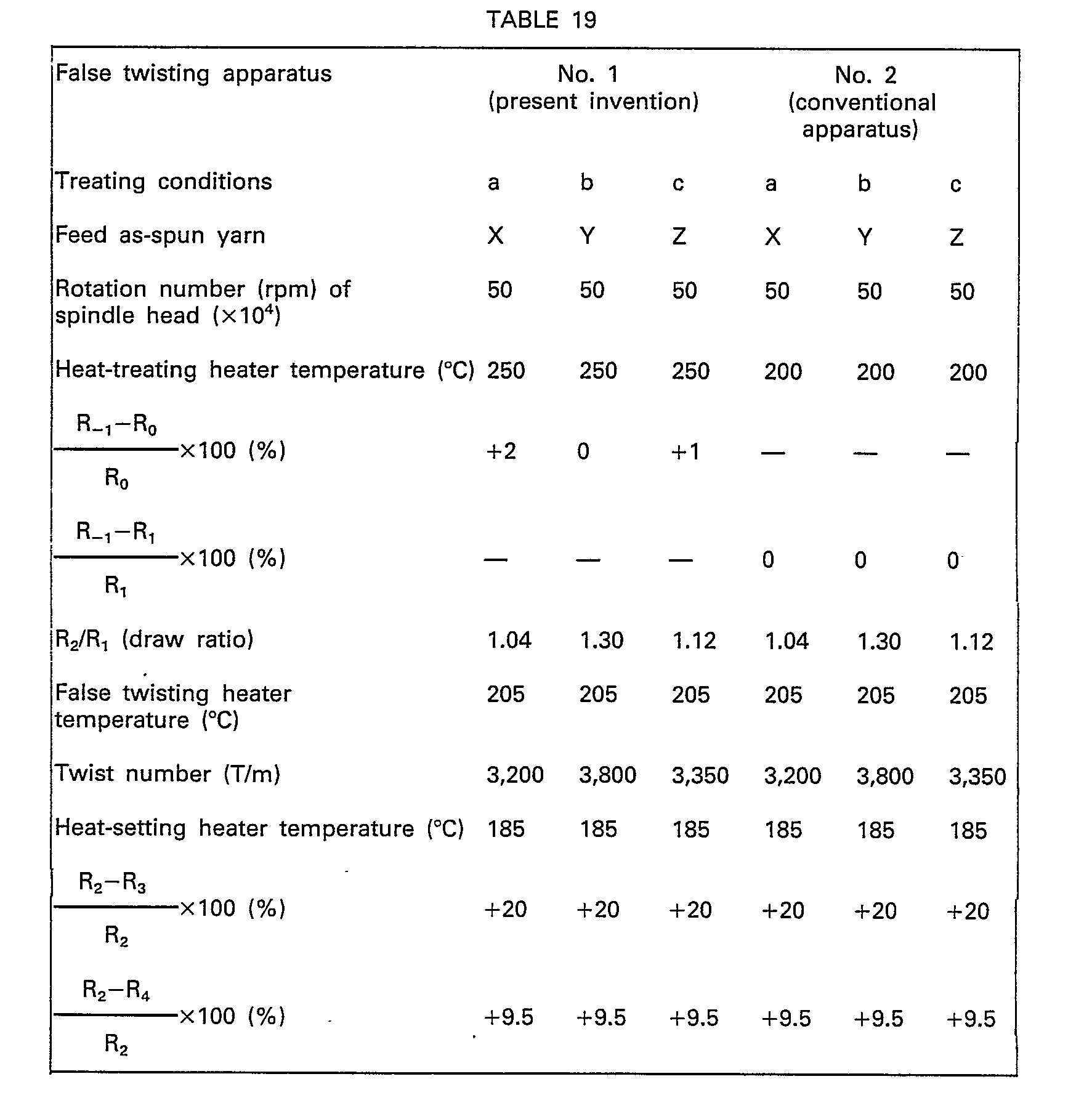


- From the results shown in Table 20, it is seen that the false twisting apparatus described in the present invention is excellent over the conventional heat-treating heater-provided false twisting apparatus because formation of fluffs and occurrence of yarn breakage are remarkably reduced and good false twisting properties can be obtained, and the false-twisted yarn obtained by using the false twisting apparatus described in the present invention is highly improved in the tight spot property, evenness of dyeing, yield of acceptable dyeing level and dyeability.
- The as-spun yarn Y of Example 10 was subjected to the partially molten-false twisting by using the apparatus No. 1 or No. 2 used in Example 10 to obtain a linen-like partially molten-false-twisted yarn. Treating conditions were as follows.

- The above conditions were commonly adopted in both the apparatuses, but the heat-treating temperature was different between the two apparatuses. Namely, this temperature was 265°C in the apparatus No. 1 and 220°C in the apparatus No. 2.
- The obtained results are shown in Table 21.

- From the results shown in Table 21, it is seen that even in case of the partially molten-false twisting treatment, the false twisting apparatus described in the present invention is advantageous over the conventional heat-treating heater-provided false twisting apparatus in that formation of fluffs and occurrence of yarn breakage are remarkably reduced, the adaptability to the false twisting treatment is improved and the dye up-take ratio of the obtained yarn is enhanced.
- Polyethylene terephthalate having an intrinsic viscosity of 0.65 dl/g was melt-extruded from a spinneret having 24 orifices, each 0.23 mm in diameter at a spinning temperature of 300°C. The yarn extruded was cooled and solidified with a stream of air at 20°C supplied in parallel to the direction of the running yarn, and then the yarn was wound at a winding speed of 4,500 m/min to give multifilaments of 50 d/24 f by using the spinning apparatus shown in Fig. 1. A mean birefringence index An of the yarn was 71 x10-3. The wound yarn was subjected to heat treatment for 0.8 second at an elongation ratio of 0% by passing through a
heat treating heater 9 as shown in Fig. 9, which was placed in an atmosphere of mixed gas containing 80 mol% of super heated steam and 20 mol% of air heated at 235°C. Subsequently the yarn was naturally cooled for 1.2 second in an atmosphere maintained at 25°C, and then the yarn was false-twisted at a false twisting temperature of 212°C at a draw ratio of 7% and a twisting number of 3,900 t/m. The tenacity and dye up-take ratio of the false-twisted yarn are 3.3 g/d and 87%, respectivelv.
Claims (14)

Priority Applications (1)
| Application Number | Priority Date | Filing Date | Title |
|---|---|---|---|
| AT83101510T ATE47163T1 (en) | 1982-02-19 | 1983-02-17 | PROCESS AND APPARATUS FOR THE MANUFACTURE OF FALSE TWIST TEXTURED EASILY DYEABLE POLYESTER YARN. |
Applications Claiming Priority (8)
| Application Number | Priority Date | Filing Date | Title |
|---|---|---|---|
| JP24561/82 | 1982-02-19 | ||
| JP2456182A JPS58144138A (en) | 1982-02-19 | 1982-02-19 | False twisting machine |
| JP9851082A JPS58220829A (en) | 1982-06-10 | 1982-06-10 | Production of polyester false twisted processed yarn improved in dyeability |
| JP98510/82 | 1982-06-10 | ||
| JP137611/82 | 1982-08-07 | ||
| JP13761182A JPS5930924A (en) | 1982-08-07 | 1982-08-07 | Production of polyester processed yarn improved in dyeability |
| JP17251882A JPS5966529A (en) | 1982-10-02 | 1982-10-02 | Production of polyester false twisted yarn |
| JP172518/82 | 1982-10-02 |
Publications (3)
| Publication Number | Publication Date |
|---|---|
| EP0087124A2 EP0087124A2 (en) | 1983-08-31 |
| EP0087124A3 EP0087124A3 (en) | 1986-03-19 |
| EP0087124B1 true EP0087124B1 (en) | 1989-10-11 |
Family
ID=27458166
Family Applications (1)
| Application Number | Title | Priority Date | Filing Date |
|---|---|---|---|
| EP19830101510 Expired EP0087124B1 (en) | 1982-02-19 | 1983-02-17 | Process and apparatus for producing easily dyeable polyester false-twisted yarns |
Country Status (2)
| Country | Link |
|---|---|
| EP (1) | EP0087124B1 (en) |
| DE (1) | DE3380700D1 (en) |
Families Citing this family (2)
| Publication number | Priority date | Publication date | Assignee | Title |
|---|---|---|---|---|
| JP4060508B2 (en) * | 2000-02-16 | 2008-03-12 | Tmtマシナリー株式会社 | Drawing false twisting machine |
| CN116427074B (en) * | 2023-04-24 | 2023-12-15 | 吴江广宇纺织有限公司 | Elasticizer and control system |
Family Cites Families (7)
| Publication number | Priority date | Publication date | Assignee | Title |
|---|---|---|---|---|
| DE2212346A1 (en) * | 1971-03-16 | 1972-09-28 | Naz Cogne S P A Soc | Apparatus and method for use in an apparatus for treating yarn |
| BE788497A (en) * | 1971-09-08 | 1973-03-07 | Bayer Ag | PROCESS AND APPARATUS FOR THE MANUFACTURE OF TEXTURED POLYESTER YARNS |
| GB1416706A (en) * | 1972-07-25 | 1975-12-03 | Scragg & Sons | Yarn texturing process |
| DE2259434A1 (en) * | 1972-12-05 | 1974-06-06 | Bayer Ag | METHOD FOR SIMULTANEOUSLY DRAW TEXTURING OF CONTINUOUS YARNS |
| US3977175A (en) * | 1973-12-13 | 1976-08-31 | Teijin Limited | Draw-texturing polyester yarns |
| US3956878A (en) * | 1974-09-10 | 1976-05-18 | Fiber Industries, Inc. | High speed texturing |
| US4426516A (en) * | 1981-03-31 | 1984-01-17 | Asahi Kasei Kogyo Kabushiki Kaisha | Polyester fiber dyeable under normal pressure |
-
1983
- 1983-02-17 DE DE8383101510T patent/DE3380700D1/en not_active Expired
- 1983-02-17 EP EP19830101510 patent/EP0087124B1/en not_active Expired
Also Published As
| Publication number | Publication date |
|---|---|
| DE3380700D1 (en) | 1989-11-16 |
| EP0087124A2 (en) | 1983-08-31 |
| EP0087124A3 (en) | 1986-03-19 |
Similar Documents
| Publication | Publication Date | Title |
|---|---|---|
| US4496505A (en) | Process for the production of a polyester fiber dyeable under normal pressure | |
| EP0013101B1 (en) | A process for producing a latent heat-bulkable polyethylene terephthalate yarn, the so produced yarn and its use in producing a bulked fabric | |
| US3977175A (en) | Draw-texturing polyester yarns | |
| CA1104777A (en) | Process | |
| EP0061770B1 (en) | Polyester fiber dyeable under normal pressure and process for the production thereof | |
| JPH0258365B2 (en) | ||
| EP1283285A2 (en) | Poly(lactic acid) fiber | |
| CA2478286C (en) | Process for producing polyester fine multifilament yarn and polyester fine false-twist textured yarn, polyester fine multifilament yarn and polyester fine false-twist textured yarn | |
| US4539805A (en) | Process and apparatus for producing easily dyeable polyester false-twisted yarns | |
| EP0059418B1 (en) | Uniformly dyeable nylon 66 fiber and process for the production thereof | |
| US6723265B1 (en) | Method for producing polyester-based combined filament yarn | |
| US3956878A (en) | High speed texturing | |
| EP0089005B1 (en) | Textured yarn and method and apparatus for producing the same | |
| EP0207489A2 (en) | Highly-shrinkable polyester fiber, process for preparation thereof, blended polyester yarn and process for preparation thereof | |
| US4096222A (en) | Process of treating polyester yarn to provide a pattern of portions that differ in dyeability | |
| JPS6242044B2 (en) | ||
| EP0087124A2 (en) | Process and apparatus for producing easily dyeable polyester false-twisted yarns | |
| US6503622B1 (en) | Texturized, combined polyester multifilament yarn and process for producing same | |
| US4835053A (en) | Dark dyeing yarn containing polyester fibers and method of preparation | |
| Pal et al. | Draw-texturing of microfiber polyester yarn | |
| US5593777A (en) | Two-component loop yarns, production thereof and use thereof as sewing and embroidery yarns | |
| EP0126055B1 (en) | Improved partially oriented nylon yarn and process | |
| US4646514A (en) | Partially oriented nylon yarn and process | |
| JPS6343484B2 (en) | ||
| CA1101648A (en) | Low-torque textured yarn and process |
Legal Events
| Date | Code | Title | Description |
|---|---|---|---|
| PUAI | Public reference made under article 153(3) epc to a published international application that has entered the european phase |
Free format text: ORIGINAL CODE: 0009012 |
|
| 17P | Request for examination filed |
Effective date: 19830217 |
|
| AK | Designated contracting states |
Designated state(s): AT BE CH DE FR GB IT LI LU NL SE |
|
| PUAL | Search report despatched |
Free format text: ORIGINAL CODE: 0009013 |
|
| AK | Designated contracting states |
Kind code of ref document: A3 Designated state(s): AT BE CH DE FR GB IT LI LU NL SE |
|
| 17Q | First examination report despatched |
Effective date: 19870825 |
|
| GRAA | (expected) grant |
Free format text: ORIGINAL CODE: 0009210 |
|
| AK | Designated contracting states |
Kind code of ref document: B1 Designated state(s): AT BE CH DE FR GB IT LI LU NL SE |
|
| PG25 | Lapsed in a contracting state [announced via postgrant information from national office to epo] |
Ref country code: SE Effective date: 19891011 Ref country code: NL Effective date: 19891011 Ref country code: IT Free format text: LAPSE BECAUSE OF FAILURE TO SUBMIT A TRANSLATION OF THE DESCRIPTION OR TO PAY THE FEE WITHIN THE PRESCRIBED TIME-LIMIT;WARNING: LAPSES OF ITALIAN PATENTS WITH EFFECTIVE DATE BEFORE 2007 MAY HAVE OCCURRED AT ANY TIME BEFORE 2007. THE CORRECT EFFECTIVE DATE MAY BE DIFFERENT FROM THE ONE RECORDED. Effective date: 19891011 Ref country code: BE Effective date: 19891011 Ref country code: AT Effective date: 19891011 |
|
| REF | Corresponds to: |
Ref document number: 47163 Country of ref document: AT Date of ref document: 19891015 Kind code of ref document: T |
|
| REF | Corresponds to: |
Ref document number: 3380700 Country of ref document: DE Date of ref document: 19891116 |
|
| ET | Fr: translation filed | ||
| REG | Reference to a national code |
Ref country code: CH Ref legal event code: PL |
|
| PG25 | Lapsed in a contracting state [announced via postgrant information from national office to epo] |
Ref country code: LU Free format text: LAPSE BECAUSE OF NON-PAYMENT OF DUE FEES Effective date: 19900228 Ref country code: LI Free format text: LAPSE BECAUSE OF NON-PAYMENT OF DUE FEES Effective date: 19900228 Ref country code: CH Free format text: LAPSE BECAUSE OF NON-PAYMENT OF DUE FEES Effective date: 19900228 |
|
| NLV1 | Nl: lapsed or annulled due to failure to fulfill the requirements of art. 29p and 29m of the patents act | ||
| PLBI | Opposition filed |
Free format text: ORIGINAL CODE: 0009260 |
|
| 26 | Opposition filed |
Opponent name: HOECHST AKTIENGESELLSCHAFT ZENTRALE PATENTABTEILUN Effective date: 19900706 |
|
| PGFP | Annual fee paid to national office [announced via postgrant information from national office to epo] |
Ref country code: GB Payment date: 19920210 Year of fee payment: 10 |
|
| PGFP | Annual fee paid to national office [announced via postgrant information from national office to epo] |
Ref country code: FR Payment date: 19920211 Year of fee payment: 10 |
|
| PGFP | Annual fee paid to national office [announced via postgrant information from national office to epo] |
Ref country code: DE Payment date: 19920331 Year of fee payment: 10 |
|
| RDAG | Patent revoked |
Free format text: ORIGINAL CODE: 0009271 |
|
| STAA | Information on the status of an ep patent application or granted ep patent |
Free format text: STATUS: PATENT REVOKED |
|
| 27W | Patent revoked |
Effective date: 19930108 |
|
| GBPR | Gb: patent revoked under art. 102 of the ep convention designating the uk as contracting state |
Free format text: 930108 |
|
| REG | Reference to a national code |
Ref country code: CH Ref legal event code: PL |
|
| APAH | Appeal reference modified |
Free format text: ORIGINAL CODE: EPIDOSCREFNO |