EP0086884A2 - Low temperature preparation of graphitized carbons using boron and silicon - Google Patents
Low temperature preparation of graphitized carbons using boron and silicon Download PDFInfo
- Publication number
- EP0086884A2 EP0086884A2 EP82111275A EP82111275A EP0086884A2 EP 0086884 A2 EP0086884 A2 EP 0086884A2 EP 82111275 A EP82111275 A EP 82111275A EP 82111275 A EP82111275 A EP 82111275A EP 0086884 A2 EP0086884 A2 EP 0086884A2
- Authority
- EP
- European Patent Office
- Prior art keywords
- fuel cell
- carbon
- mixture
- silicon
- boron
- Prior art date
- Legal status (The legal status is an assumption and is not a legal conclusion. Google has not performed a legal analysis and makes no representation as to the accuracy of the status listed.)
- Withdrawn
Links
Images
Classifications
-
- C—CHEMISTRY; METALLURGY
- C04—CEMENTS; CONCRETE; ARTIFICIAL STONE; CERAMICS; REFRACTORIES
- C04B—LIME, MAGNESIA; SLAG; CEMENTS; COMPOSITIONS THEREOF, e.g. MORTARS, CONCRETE OR LIKE BUILDING MATERIALS; ARTIFICIAL STONE; CERAMICS; REFRACTORIES; TREATMENT OF NATURAL STONE
- C04B35/00—Shaped ceramic products characterised by their composition; Ceramics compositions; Processing powders of inorganic compounds preparatory to the manufacturing of ceramic products
- C04B35/515—Shaped ceramic products characterised by their composition; Ceramics compositions; Processing powders of inorganic compounds preparatory to the manufacturing of ceramic products based on non-oxide ceramics
- C04B35/52—Shaped ceramic products characterised by their composition; Ceramics compositions; Processing powders of inorganic compounds preparatory to the manufacturing of ceramic products based on non-oxide ceramics based on carbon, e.g. graphite
-
- H—ELECTRICITY
- H01—ELECTRIC ELEMENTS
- H01M—PROCESSES OR MEANS, e.g. BATTERIES, FOR THE DIRECT CONVERSION OF CHEMICAL ENERGY INTO ELECTRICAL ENERGY
- H01M4/00—Electrodes
- H01M4/86—Inert electrodes with catalytic activity, e.g. for fuel cells
- H01M4/96—Carbon-based electrodes
-
- H—ELECTRICITY
- H01—ELECTRIC ELEMENTS
- H01M—PROCESSES OR MEANS, e.g. BATTERIES, FOR THE DIRECT CONVERSION OF CHEMICAL ENERGY INTO ELECTRICAL ENERGY
- H01M8/00—Fuel cells; Manufacture thereof
- H01M8/02—Details
- H01M8/0202—Collectors; Separators, e.g. bipolar separators; Interconnectors
- H01M8/0204—Non-porous and characterised by the material
- H01M8/0213—Gas-impermeable carbon-containing materials
-
- Y—GENERAL TAGGING OF NEW TECHNOLOGICAL DEVELOPMENTS; GENERAL TAGGING OF CROSS-SECTIONAL TECHNOLOGIES SPANNING OVER SEVERAL SECTIONS OF THE IPC; TECHNICAL SUBJECTS COVERED BY FORMER USPC CROSS-REFERENCE ART COLLECTIONS [XRACs] AND DIGESTS
- Y02—TECHNOLOGIES OR APPLICATIONS FOR MITIGATION OR ADAPTATION AGAINST CLIMATE CHANGE
- Y02E—REDUCTION OF GREENHOUSE GAS [GHG] EMISSIONS, RELATED TO ENERGY GENERATION, TRANSMISSION OR DISTRIBUTION
- Y02E60/00—Enabling technologies; Technologies with a potential or indirect contribution to GHG emissions mitigation
- Y02E60/30—Hydrogen technology
- Y02E60/50—Fuel cells
-
- Y—GENERAL TAGGING OF NEW TECHNOLOGICAL DEVELOPMENTS; GENERAL TAGGING OF CROSS-SECTIONAL TECHNOLOGIES SPANNING OVER SEVERAL SECTIONS OF THE IPC; TECHNICAL SUBJECTS COVERED BY FORMER USPC CROSS-REFERENCE ART COLLECTIONS [XRACs] AND DIGESTS
- Y02—TECHNOLOGIES OR APPLICATIONS FOR MITIGATION OR ADAPTATION AGAINST CLIMATE CHANGE
- Y02P—CLIMATE CHANGE MITIGATION TECHNOLOGIES IN THE PRODUCTION OR PROCESSING OF GOODS
- Y02P70/00—Climate change mitigation technologies in the production process for final industrial or consumer products
- Y02P70/50—Manufacturing or production processes characterised by the final manufactured product
Definitions
- the present invention is directed to a method for enhancing the corrosion resistance of carbonaceous components of a fuel cell.
- the present invention is directed to a method for enhancing the corrosion resistance of carbonaceous components in a fuel cell by doping the carbon with boron or silicon and graphitizing the carbon by heating.
- a typical fuel cell is an electrochemical cell comprising a matrix for holding electrolyte and an electrode disposed on each side of the matrix and in contact therewith.
- Reactant gases such as hydrogen as fuel and oxygen as oxidant may be fed to the nonelectrolyte facing side of each electrode.
- separator plates may be disposed between adjacent cells. Due to the low solubility of reactant gases, such as hydrogen and oxygen in electrolytes, the fuel cell reactions take place at the electrode-electrolyte interface.
- the required surface area at the interface is typically obtained utilizing porous materials which fulfill the functions of providing contact between electrolyte and gas, catalyzing the reaction, maintaining the electrolyte in a very thin area on the surface of the electrode, and acting as leads for the transmission of electrons.
- aqueous electrolyte fuel cells may comprise carbonaceous material, such as the cathode, separator plates and .current collectors.
- carbonaceous material such as the cathode, separator plates and .current collectors.
- a particular problem in acid electrolyte fuel cells is that at operating temperatures, typically above 200° C , the carbonaceous components are particularly susceptible to corrosion. The frequency of replacement of such corroded carbonaceous components may be a major disadvantage of fuel cells which may make them less commercially attractive than other sources of electrical energy.
- carbonaceous components for fuel cells in particular the cathodes, may be provided which exhibit enhanced resistance to corrosion by introducing boron or silicon into the carbonaceous material utilized in the fuel cell component. Subsequent heat treatment of the carbonaceous boron-containing or silicon- containing mixture produces graphitized carbon having enhanced corrosion resistance.
- degree of lattice ordering hereinafter referred to as graphitization
- the closeness of approach for the lattice ordering (d 0 ) to 3.35A defines the degree of graphitization.
- boron may be introduced into carbonaceous material conventionally utilized in the production in components for fuel cells.
- Carbonaceous material such as carbon-black may be intimately mixed with a boric acid solution by ultrasonic agitation, forming a slurry which is then evaporated to dryness.
- concentration of the boric acid solution and the proportions of the solution mixed with carbon are not particularly critical, however, slurries formed utilizing from about 80% to about 98% carbon by weight with 20% to 2% by weight boric acid in a 0.3M solution are preferred.
- the slurry may then be dried and the resulting mixed solids heated for approximately one hour at temperatures ranging from 1000-2000 0 C in an inert atmosphere. After the heat treatment the boron doped carbon may be rinsed, for example, in boiling distilled water to remove residual boric acid.
- Heat treatment at a temperature sufficient to graphitize the carbons is necessary. Such a temperature may be as low as 1000° C. While at least 1600° C is preferred, heat treatment above 2500° C may provide improved graphitized carbon according to the present invention. However, temperatures less than about 2500° C are preferred.
- boron-doped carbon which has been heat treated as described above exhibits superior resistance to corrosion at fuel cell cathode operating conditions. Resistance to corrosion is particularly advantageous when the boron-doped carbon is heat treated from 1000° - 1600° C.
- the boron content of the heat treated graphitized carbon may vary depending on the rate of cooling. However, the degree of graphitization which occurs is not due only to heat treatment. The presence of boron is believed to be critical to achieving the degree of graphitization attainable according to the present invention.
- FIG. 1 there is shown a plot of d 0 (half the carbon unit cell c dimension) versus the temperature of heat treatment for heat treated Vulcan (Cabot's Vulcan XC-72R) samples undoped or doped by boron.
- the value for d 0 for natural graphite is 3.35A, therefore, it may be seen from Figure 1 that a higher degree of graphitization may be obtained by'boron doping and heat treatment at a lower temperature rather than by heat treatment alone.
- Figure 1 shows that in heat treatments above 1400° C the boron- ° doped carbons have a d 0 less than 3.47 A.
- FIG. 2 there is shown a plot of d 0 for heat treated Vulcan XC-72R and heat treated boron doped Vulcan XC-72R versus BET (Brunauer-Emmett-Teller method) surface areas. It may be seen from Figure 2 that the least graphitic boron-doped carbon which is that carbon treated at 1600° C having the d 0 which deviates most from » the value of 3.35A has a higher BET surface area and a higher degree of graphitization than the most graphitic undoped carbon (which is the undoped carbon heat treated at approximately 3000°).
- BET Brunauer-Emmett-Teller method
- Carbonaceous components of fuel cells exhibiting enhanced resistance to corrosion may also be provided according to the present invention by doping carbon with silicon and heat treating.
- carbon black which may be used in the manufacture of components for fuel cells may be slurried with fumed silicon oxide (Cabot's Cab-0-Sil).
- the carbon black may be impregnated with silicon by mixing with an aqueous solution of sodium silicate.
- the carbon black may be slurried with fumed silicon oxide, evaporated to dryness and heat treated for approximately one hour.at approximately 800° C in an inert atmosphere.
- the silicon impregnated carbon may be heated at 2300° C for approximately one hour in an inert atmosphere. In either method, subsequent to heat treatment the carbon may be boiled in aqueous sodium hydroxide to remove unreacted silicon oxide.
- Heat treatment at a temperature sufficient to graphitize the carbon is necessary. Such temperature may be as low as 1400° C. A temperature of at least 1800° C is preferred. Heat treatment as temperatures greater than 1800° C may provide improved graphitized carbon according to the present invention, however, temperatures less than about 2500° C are preferred.
- FIG. 3 there is shown a plot of d 0 versus heat treatment temperatures for samples of turbostratic carbon black (Cabot's Vulcan XC -72R) made by slurrying with fumed silicon oxide.
- the silicon doped samples exhibit a d 0 value closer to 3.35 A than the undoped samples, thereby indicating a higher degree of graphitization for the silicon doped samples.
- FIG 4 there is shown a plot of d 0 versus d 0 for silicon doped and undoped carbon samples.
- the silicon doped samples not only are more highly graphitized, but also exhibit a higher BET surface area than even the most graphitized undoped sample.
- Tafel slopes the slope of potential versus logarithm of current density
- the silicon doped carbon exhibits lower Tafel slopes than the undoped heat treated samples.
- a low value for the Tafel slope means that corrosion currents are lower at potentials of interest in fuel cells (0.65-0.8 V) than those for materials showing higher Tafel slopes.
- Table 1 Shown below in Table 1 is a summary of properties shown in Figures 3, 4 and 5 of silicon doped versus undoped carbon. Additionally, in Table 1 there is shown a comparison of corrosion resistance, as evidenced by the corrosion current at 1000 minutes. The corrosion test procedure is described by EPRI Publication No. EM-1664, p. A-1 (1981), published by the Electric Power Research Institute, Palo Alto, California 94303.
- the heat treated silicon doped samples were tested for corrosion at one volt at 200° C in concentrated phosphoric acid.
- the corrosion characteristics are shown in Table I above with the comparable corrosion characteristics for an undoped Vulcan XC-72R carbon sample which had been similarly heat treated.
- the silicon doped carbon samples show significantly lower corrosion current (i at 1000 minutes) than the comparable heat treated carbon in the absence of silicon.
- the silicon doped carbon samples exhibit a higher surface area retention (BET surface area) than the undoped carbon.
Abstract
A method for fabricating graphitized carbonaceous components for a fuel cell is provided wherein graphitized carbon contains at least one element from the group consisting of boron and silicon. The graphitized carbon containing components exhibit improved corrosion resistance at fuel cell operating temperatures.
Description
- The present invention is directed to a method for enhancing the corrosion resistance of carbonaceous components of a fuel cell. In particular the present invention is directed to a method for enhancing the corrosion resistance of carbonaceous components in a fuel cell by doping the carbon with boron or silicon and graphitizing the carbon by heating.
- A typical fuel cell is an electrochemical cell comprising a matrix for holding electrolyte and an electrode disposed on each side of the matrix and in contact therewith. Reactant gases such as hydrogen as fuel and oxygen as oxidant may be fed to the nonelectrolyte facing side of each electrode. In a stack of fuel cells separator plates may be disposed between adjacent cells. Due to the low solubility of reactant gases, such as hydrogen and oxygen in electrolytes, the fuel cell reactions take place at the electrode-electrolyte interface. The required surface area at the interface is typically obtained utilizing porous materials which fulfill the functions of providing contact between electrolyte and gas, catalyzing the reaction, maintaining the electrolyte in a very thin area on the surface of the electrode, and acting as leads for the transmission of electrons.
- In typical aqueous electrolyte fuel cells, several of the components may comprise carbonaceous material, such as the cathode, separator plates and .current collectors. A particular problem in acid electrolyte fuel cells is that at operating temperatures, typically above 200° C, the carbonaceous components are particularly susceptible to corrosion. The frequency of replacement of such corroded carbonaceous components may be a major disadvantage of fuel cells which may make them less commercially attractive than other sources of electrical energy.
- It is therefore an object of the present invention to provide a method for fabricating carbonaceous components for fuel cells which exhibit enhanced resistance to corrosion under fuel cell operating conditions.
- It is a further object of the present invention to provide fuel cells which exhibit enhanced resistance to corrosion at operating temperatures and conditions.
- In the accompanying drawings:
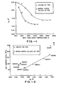
- Figure 1 is a graph of d0 (half the carbon cell unit c dimension) of heat-treated undoped and boron-doped graphitized carbon versus heat treatment temperature.
- Figure 2 is a graph of d0 heat-treated undoped and boron-doped graphitized carbon versus BET surface area.
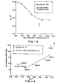
- Figure 3 is a graph of d0 of heat-treated undoped and silicon-doped graphitized carbon versus heat treatment temperature.
- Figure 4 is a graph of d0 of heat-treated undoped and silicon-doped graphitized carbon versus BET surface area.
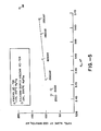
- Figure 5 is a graph of Tafel slope versus d0 for heat-treated undoped and silicon-doped graphitized carbons.
- According to the present invention, carbonaceous components for fuel cells, in particular the cathodes, may be provided which exhibit enhanced resistance to corrosion by introducing boron or silicon into the carbonaceous material utilized in the fuel cell component. Subsequent heat treatment of the carbonaceous boron-containing or silicon- containing mixture produces graphitized carbon having enhanced corrosion resistance. Furthermore the degree of lattice ordering (hereinafter referred to as graphitization) which is achieved by the method according to the present invention is greater than the degree of graphitization which may be achieved by heat-treating the carbonaceous material in absence of boron or silicon. The closeness of approach for the lattice ordering (d0) to 3.35A defines the degree of graphitization.
- According to the present invention, boron may be introduced into carbonaceous material conventionally utilized in the production in components for fuel cells. Carbonaceous material such as carbon-black may be intimately mixed with a boric acid solution by ultrasonic agitation, forming a slurry which is then evaporated to dryness. The concentration of the boric acid solution and the proportions of the solution mixed with carbon are not particularly critical, however, slurries formed utilizing from about 80% to about 98% carbon by weight with 20% to 2% by weight boric acid in a 0.3M solution are preferred. The slurry may then be dried and the resulting mixed solids heated for approximately one hour at temperatures ranging from 1000-20000 C in an inert atmosphere. After the heat treatment the boron doped carbon may be rinsed, for example, in boiling distilled water to remove residual boric acid.
- Heat treatment at a temperature sufficient to graphitize the carbons is necessary. Such a temperature may be as low as 1000° C. While at least 1600° C is preferred, heat treatment above 2500° C may provide improved graphitized carbon according to the present invention. However, temperatures less than about 2500° C are preferred.
- It has been found that boron-doped carbon which has been heat treated as described above exhibits superior resistance to corrosion at fuel cell cathode operating conditions. Resistance to corrosion is particularly advantageous when the boron-doped carbon is heat treated from 1000° - 1600° C. The boron content of the heat treated graphitized carbon may vary depending on the rate of cooling. However, the degree of graphitization which occurs is not due only to heat treatment. The presence of boron is believed to be critical to achieving the degree of graphitization attainable according to the present invention.
- Referring to Figure 1, there is shown a plot of d0 (half the carbon unit cell c dimension) versus the temperature of heat treatment for heat treated Vulcan (Cabot's Vulcan XC-72R) samples undoped or doped by boron. The value for d0 for natural graphite is 3.35A, therefore, it may be seen from Figure 1 that a higher degree of graphitization may be obtained by'boron doping and heat treatment at a lower temperature rather than by heat treatment alone. Figure 1 shows that in heat treatments above 1400° C the boron- ° doped carbons have a d0 less than 3.47 A.
- Referring to Figure 2, there is shown a plot of d0 for heat treated Vulcan XC-72R and heat treated boron doped Vulcan XC-72R versus BET (Brunauer-Emmett-Teller method) surface areas. It may be seen from Figure 2 that the least graphitic boron-doped carbon which is that carbon treated at 1600° C having the d0 which deviates most from » the value of 3.35A has a higher BET surface area and a higher degree of graphitization than the most graphitic undoped carbon (which is the undoped carbon heat treated at approximately 3000°). As shown in Figure 2, all of the heat-treated boron-doped carbons have higher BET surface areas than the most graphitic undoped carbon. Thus, the achievement of substantially improved BET surface area is a further advantage of the present invention since it is advantageous to have the highest surface area possible in fuel cell components, particularly wherein the surface involves catalytic reactions.
- Carbonaceous components of fuel cells exhibiting enhanced resistance to corrosion may also be provided according to the present invention by doping carbon with silicon and heat treating. According to the present invention carbon black which may be used in the manufacture of components for fuel cells may be slurried with fumed silicon oxide (Cabot's Cab-0-Sil). Alternatively, the carbon black may be impregnated with silicon by mixing with an aqueous solution of sodium silicate. Preferably, the carbon black may be slurried with fumed silicon oxide, evaporated to dryness and heat treated for approximately one hour.at approximately 800° C in an inert atmosphere. If the impregnation method is used, the silicon impregnated carbon may be heated at 2300° C for approximately one hour in an inert atmosphere. In either method, subsequent to heat treatment the carbon may be boiled in aqueous sodium hydroxide to remove unreacted silicon oxide.
- Heat treatment at a temperature sufficient to graphitize the carbon is necessary. Such temperature may be as low as 1400° C. A temperature of at least 1800° C is preferred. Heat treatment as temperatures greater than 1800° C may provide improved graphitized carbon according to the present invention, however, temperatures less than about 2500° C are preferred.
- Referring to Figure 3, there is shown a plot of d0 versus heat treatment temperatures for samples of turbostratic carbon black (Cabot's Vulcan XC-72R) made by slurrying with fumed silicon oxide. As may be seen from Figure 3, the silicon doped samples exhibit a d0 value closer to 3.35 A than the undoped samples, thereby indicating a higher degree of graphitization for the silicon doped samples.
- Referring to Figure 4, there is shown a plot of d0 versus d0 for silicon doped and undoped carbon samples. As may be seen from Figure 4, the silicon doped samples not only are more highly graphitized, but also exhibit a higher BET surface area than even the most graphitized undoped sample.
- Referring to Figure 5, there is shown a plot of Tafel slopes (the slope of potential versus logarithm of current density) at 1000 minutes versus d0 for heat treated undoped and silicon doped carbon. It may be seen from Figure 5, that the silicon doped carbon exhibits lower Tafel slopes than the undoped heat treated samples. A low value for the Tafel slope means that corrosion currents are lower at potentials of interest in fuel cells (0.65-0.8 V) than those for materials showing higher Tafel slopes.
- Shown below in Table 1 is a summary of properties shown in Figures 3, 4 and 5 of silicon doped versus undoped carbon. Additionally, in Table 1 there is shown a comparison of corrosion resistance, as evidenced by the corrosion current at 1000 minutes. The corrosion test procedure is described by EPRI Publication No. EM-1664, p. A-1 (1981), published by the Electric Power Research Institute, Palo Alto, California 94303.

- The heat treated silicon doped samples were tested for corrosion at one volt at 200° C in concentrated phosphoric acid. The corrosion characteristics are shown in Table I above with the comparable corrosion characteristics for an undoped Vulcan XC-72R carbon sample which had been similarly heat treated. In all instances the silicon doped carbon samples show significantly lower corrosion current (i at 1000 minutes) than the comparable heat treated carbon in the absence of silicon. In addition, the silicon doped carbon samples exhibit a higher surface area retention (BET surface area) than the undoped carbon.
- Samples of boron doped carbon were heat treated at various temperatures and the corrosion currents tested as shown in TABLE II.

- From Table II it may be seen that the boron doped carbons which were heat treated exhibit superior resistance to corrosion at fuel cell cathode operating conditions. Corrosion currents were monitored at 1 volt in both 165° and 200° C phosphoric acid. Corrosion currents at 1000 minutes are given in Table II. The values for undoped Vulcan XC-72R and Vulcan XC-72R 2500HT are included for a comparison. It may be seen from Table II that, although resistance to corrosion in the heat treated boron doped samples improves with higher temperature of heat treatment, treatments above 1600° C exhibit only small improvements.
Claims (11)
1. A method of fabricating a graphitized carbon containing component for an electrochemical fuel cell comprising the steps of;
a) intimately mixing carbon with an aqueous solution of boric acid;
b) removing water from the mixture from step a);
c) heating the mixture from step b) in an inert atmosphere at a temperature sufficient to graphitize said mixture.
2. A method according to Claim 1 wherein step c) is performed at a temperature in the range 1000° to 2500° C.
3. A method for fabricating a graphitized carbon containing component for an electrochemical fuel cell comprising the steps of;
a) intimately mixing carbon with an aqueous solution of silicon oxide;
b) removing water from the mixture from step a);
c) heating the mixture from step b) in an inert atmosphere at a temperature sufficient to graphitize said mixture.
4. A method according to Claim 3 wherein said step c) is performed at a temperature range of 1400° to 2500° C.
5. A method for fabricating a graphitized carbon containing component for an electrochemical fuel cell comprising the steps of;
a) intimately mixing carbon with an aqueous solution of sodium silicate;
b) removing water from the mixture from step a);
c) heating the dry mixture from step b) in an inert atmosphere at a temperature sufficient to graphitize said mixture.
6. A method according to Claim 5 wherein said step c) is performed at a temperature with the range of 1400° C to 2500° C.
7. In an electrochemical fuel cell, the improvement comprising a carbonaceous component comprising graphitized carbon and an element from the group consisting of silicon and boron.
8. A fuel cell according to Claim 7 wherein said graphitized carbon is characterized by a half unit cell c dimension of less than 3.47 A.
9. A fuel cell according to Claim 8 wherein said component is a cathode.
10. A fuel cell according to Claim 8 wherein said component is a current collector.
11. A fuel cell according to Claim 8 wherein said component is a separator plate.
Applications Claiming Priority (2)
| Application Number | Priority Date | Filing Date | Title |
|---|---|---|---|
| US35100782A | 1982-02-22 | 1982-02-22 | |
| US351007 | 1982-02-22 |
Publications (1)
| Publication Number | Publication Date |
|---|---|
| EP0086884A2 true EP0086884A2 (en) | 1983-08-31 |
Family
ID=23379195
Family Applications (1)
| Application Number | Title | Priority Date | Filing Date |
|---|---|---|---|
| EP82111275A Withdrawn EP0086884A2 (en) | 1982-02-22 | 1982-12-06 | Low temperature preparation of graphitized carbons using boron and silicon |
Country Status (2)
| Country | Link |
|---|---|
| EP (1) | EP0086884A2 (en) |
| JP (1) | JPS58145609A (en) |
Cited By (5)
| Publication number | Priority date | Publication date | Assignee | Title |
|---|---|---|---|---|
| FR2585187A1 (en) * | 1985-07-17 | 1987-01-23 | Int Fuel Cells Corp | CARBON-GRAPHITE COMPONENT FOR ELECTROCHEMICAL CELL AND METHOD FOR THE PRODUCTION THEREOF |
| EP0903795A1 (en) * | 1996-11-26 | 1999-03-24 | Kao Corporation | Negative electrode material for nonaqueous secondary battery |
| WO2001092151A1 (en) * | 2000-05-31 | 2001-12-06 | Showa Denko K.K. | Electrically conductive fine carbon composite, catalyst for solid polymer fuel cell and fuel battery |
| US6346225B1 (en) | 1996-12-20 | 2002-02-12 | Danionics A/S | Preparation of modified cokes and/or blacks |
| US6780388B2 (en) | 2000-05-31 | 2004-08-24 | Showa Denko K.K. | Electrically conducting fine carbon composite powder, catalyst for polymer electrolyte fuel battery and fuel battery |
Families Citing this family (2)
| Publication number | Priority date | Publication date | Assignee | Title |
|---|---|---|---|---|
| JPH0711963B2 (en) * | 1985-08-31 | 1995-02-08 | 東洋紡績株式会社 | Carbon-based electrode material for flow-through electrolyzer |
| JPH061701B2 (en) * | 1987-11-18 | 1994-01-05 | 富士電機株式会社 | Catalyst carrier for fuel cell electrodes |
Family Cites Families (1)
| Publication number | Priority date | Publication date | Assignee | Title |
|---|---|---|---|---|
| JPS543682A (en) * | 1977-06-09 | 1979-01-11 | Daikin Ind Ltd | Operation control valve of agaicultural machinery |
-
1982
- 1982-12-06 EP EP82111275A patent/EP0086884A2/en not_active Withdrawn
- 1982-12-24 JP JP57235102A patent/JPS58145609A/en active Pending
Cited By (7)
| Publication number | Priority date | Publication date | Assignee | Title |
|---|---|---|---|---|
| FR2585187A1 (en) * | 1985-07-17 | 1987-01-23 | Int Fuel Cells Corp | CARBON-GRAPHITE COMPONENT FOR ELECTROCHEMICAL CELL AND METHOD FOR THE PRODUCTION THEREOF |
| US4938942A (en) * | 1985-07-17 | 1990-07-03 | International Fuel Cells | Carbon graphite component for an electrochemical cell and method for making the component |
| EP0903795A1 (en) * | 1996-11-26 | 1999-03-24 | Kao Corporation | Negative electrode material for nonaqueous secondary battery |
| EP0903795A4 (en) * | 1996-11-26 | 2005-03-16 | Kao Corp | Negative electrode material for nonaqueous secondary battery |
| US6346225B1 (en) | 1996-12-20 | 2002-02-12 | Danionics A/S | Preparation of modified cokes and/or blacks |
| WO2001092151A1 (en) * | 2000-05-31 | 2001-12-06 | Showa Denko K.K. | Electrically conductive fine carbon composite, catalyst for solid polymer fuel cell and fuel battery |
| US6780388B2 (en) | 2000-05-31 | 2004-08-24 | Showa Denko K.K. | Electrically conducting fine carbon composite powder, catalyst for polymer electrolyte fuel battery and fuel battery |
Also Published As
| Publication number | Publication date |
|---|---|
| JPS58145609A (en) | 1983-08-30 |
Similar Documents
| Publication | Publication Date | Title |
|---|---|---|
| Ravikumar et al. | Effect of methanol crossover in a liquid‐feed polymer‐electrolyte direct methanol fuel cell | |
| JP4772254B2 (en) | Conductive fine carbon composite powder, catalyst for polymer electrolyte fuel cell and fuel cell | |
| US6780388B2 (en) | Electrically conducting fine carbon composite powder, catalyst for polymer electrolyte fuel battery and fuel battery | |
| Wu et al. | Titanium dioxide-supported non-precious metal oxygen reduction electrocatalyst | |
| JP3383953B2 (en) | Method for producing graphite member for polymer electrolyte fuel cell | |
| US20160013497A1 (en) | Improved electrode for flow batteries | |
| US8716167B2 (en) | Catalyst for fuel cell and polymer electrolyte fuel cell using the same | |
| KR101202122B1 (en) | Catalyst, process for production of the same, and use of the same | |
| KR100512221B1 (en) | Electrode Catalyst for Fuel Cell and Fuel Cell Using the Same | |
| KR102081006B1 (en) | Method for producing carbon felt electrode for redox flow battery | |
| WO2003058739A1 (en) | Porous carbon body for a fuel cell having an electronically conductive hydrophilic agent | |
| KR20180076957A (en) | Cathode for fuel cell, and method for preparing membrane electrode assembly comprising the same | |
| WO2014109957A1 (en) | Improved bipolar plate for flow batteries | |
| JP2006310201A (en) | Gas diffusion layer for fuel cell and fuel cell using it | |
| EP0086884A2 (en) | Low temperature preparation of graphitized carbons using boron and silicon | |
| US4938942A (en) | Carbon graphite component for an electrochemical cell and method for making the component | |
| JPS61161666A (en) | Electrochemical battery separator plate, manufacture thereofand fuel battery | |
| CA2434086A1 (en) | Catalyst composition for cell, gas diffusion layer, and fuel cell comprising the same | |
| JP6310413B2 (en) | Lithium air secondary battery, method for producing catalyst for air electrode, and method for producing lithium air secondary battery | |
| CN114097120A (en) | Composition for fuel cell catalyst and fuel cell comprising same | |
| Duman et al. | Acid modified graphite felt cathode electrode for low temperature H2/Br2 redox flow battery | |
| JPH11317231A (en) | Carbon-based electrode material for electrolytic cell | |
| JP2689686B2 (en) | Method for producing electrode catalyst layer for phosphoric acid fuel cell | |
| JPH06196173A (en) | Fuel cell | |
| Manjunath et al. | Rama pem fuel cell” |
Legal Events
| Date | Code | Title | Description |
|---|---|---|---|
| PUAI | Public reference made under article 153(3) epc to a published international application that has entered the european phase |
Free format text: ORIGINAL CODE: 0009012 |
|
| AK | Designated contracting states |
Designated state(s): AT BE CH DE FR GB IT LI LU NL SE |
|
| 17P | Request for examination filed |
Effective date: 19831111 |
|
| STAA | Information on the status of an ep patent application or granted ep patent |
Free format text: STATUS: THE APPLICATION HAS BEEN WITHDRAWN |
|
| 18W | Application withdrawn |
Withdrawal date: 19841016 |
|
| R18W | Application withdrawn (corrected) |
Effective date: 19841016 |
|
| RIN1 | Information on inventor provided before grant (corrected) |
Inventor name: STONEHART, PAUL |