EP0086797B1 - Instrument de mesure de la reflectance - Google Patents
Instrument de mesure de la reflectance Download PDFInfo
- Publication number
- EP0086797B1 EP0086797B1 EP82902517A EP82902517A EP0086797B1 EP 0086797 B1 EP0086797 B1 EP 0086797B1 EP 82902517 A EP82902517 A EP 82902517A EP 82902517 A EP82902517 A EP 82902517A EP 0086797 B1 EP0086797 B1 EP 0086797B1
- Authority
- EP
- European Patent Office
- Prior art keywords
- strip
- gate
- light
- reflectance meter
- meter
- Prior art date
- Legal status (The legal status is an assumption and is not a legal conclusion. Google has not performed a legal analysis and makes no representation as to the accuracy of the status listed.)
- Expired
Links
Images


Classifications
-
- G—PHYSICS
- G01—MEASURING; TESTING
- G01N—INVESTIGATING OR ANALYSING MATERIALS BY DETERMINING THEIR CHEMICAL OR PHYSICAL PROPERTIES
- G01N21/00—Investigating or analysing materials by the use of optical means, i.e. using sub-millimetre waves, infrared, visible or ultraviolet light
- G01N21/17—Systems in which incident light is modified in accordance with the properties of the material investigated
- G01N21/47—Scattering, i.e. diffuse reflection
- G01N21/4738—Diffuse reflection, e.g. also for testing fluids, fibrous materials
- G01N21/474—Details of optical heads therefor, e.g. using optical fibres
-
- F—MECHANICAL ENGINEERING; LIGHTING; HEATING; WEAPONS; BLASTING
- F16—ENGINEERING ELEMENTS AND UNITS; GENERAL MEASURES FOR PRODUCING AND MAINTAINING EFFECTIVE FUNCTIONING OF MACHINES OR INSTALLATIONS; THERMAL INSULATION IN GENERAL
- F16H—GEARING
- F16H7/00—Gearings for conveying rotary motion by endless flexible members
- F16H7/08—Means for varying tension of belts, ropes, or chains
- F16H7/10—Means for varying tension of belts, ropes, or chains by adjusting the axis of a pulley
- F16H7/12—Means for varying tension of belts, ropes, or chains by adjusting the axis of a pulley of an idle pulley
- F16H7/1209—Means for varying tension of belts, ropes, or chains by adjusting the axis of a pulley of an idle pulley with vibration damping means
- F16H7/1236—Means for varying tension of belts, ropes, or chains by adjusting the axis of a pulley of an idle pulley with vibration damping means of the fluid and restriction type, e.g. dashpot
-
- G—PHYSICS
- G01—MEASURING; TESTING
- G01N—INVESTIGATING OR ANALYSING MATERIALS BY DETERMINING THEIR CHEMICAL OR PHYSICAL PROPERTIES
- G01N21/00—Investigating or analysing materials by the use of optical means, i.e. using sub-millimetre waves, infrared, visible or ultraviolet light
- G01N21/84—Systems specially adapted for particular applications
- G01N21/8483—Investigating reagent band
-
- F—MECHANICAL ENGINEERING; LIGHTING; HEATING; WEAPONS; BLASTING
- F16—ENGINEERING ELEMENTS AND UNITS; GENERAL MEASURES FOR PRODUCING AND MAINTAINING EFFECTIVE FUNCTIONING OF MACHINES OR INSTALLATIONS; THERMAL INSULATION IN GENERAL
- F16H—GEARING
- F16H7/00—Gearings for conveying rotary motion by endless flexible members
- F16H7/08—Means for varying tension of belts, ropes, or chains
- F16H2007/0802—Actuators for final output members
- F16H2007/0806—Compression coil springs
-
- F—MECHANICAL ENGINEERING; LIGHTING; HEATING; WEAPONS; BLASTING
- F16—ENGINEERING ELEMENTS AND UNITS; GENERAL MEASURES FOR PRODUCING AND MAINTAINING EFFECTIVE FUNCTIONING OF MACHINES OR INSTALLATIONS; THERMAL INSULATION IN GENERAL
- F16H—GEARING
- F16H7/00—Gearings for conveying rotary motion by endless flexible members
- F16H7/08—Means for varying tension of belts, ropes, or chains
- F16H7/0848—Means for varying tension of belts, ropes, or chains with means for impeding reverse motion
- F16H2007/0859—Check valves
-
- F—MECHANICAL ENGINEERING; LIGHTING; HEATING; WEAPONS; BLASTING
- F16—ENGINEERING ELEMENTS AND UNITS; GENERAL MEASURES FOR PRODUCING AND MAINTAINING EFFECTIVE FUNCTIONING OF MACHINES OR INSTALLATIONS; THERMAL INSULATION IN GENERAL
- F16H—GEARING
- F16H7/00—Gearings for conveying rotary motion by endless flexible members
- F16H7/08—Means for varying tension of belts, ropes, or chains
- F16H2007/0889—Path of movement of the finally actuated member
- F16H2007/0891—Linear path
Definitions
- the present invention relates to a reflectance meter.
- the invention is directed to a reflectance meter for use in a blood glucose tester for measuring the colour change of test strips treated with the blood to be tested.
- each individual test strip is encoded and the code is read when the test strip is inserted in the reflectometer.
- coding of each strip is not necessary and such individual coding makes this device and the test strips too expensive for day-to-day use by diabetics. It is not necessary to adjust the meter for each strip, but only for each type or make of strip.
- the present invention uses commonly available test strips but encodes the strip gate in which the test strips are inserted.
- Each strip gate is designed for a particular type or make of test strip, and the strip gates are interchangeable in the reflectometer. It is the code on the strip gate, rather than the strip itself, which is read by the reflectometer. This results in significant costs savings since the reflectometer can be used with commonly available strips, yet the device can compensate for the characteristics of the particular type of strip being used.
- the aim of the invention is to provide an improved reflectance meter which is accurate and reliable, yet portable, which can be manufactured inexpensively, and which is easy to operate and practically foolproof.
- the present invention provides a reflectance meter for measuring blood glucose level of a blood sample on a treated strip, the reflectance meter comprising optical testing means having strip receiving means, a light source, and at least one light sensitive device, the light sensitive device being positioned to receive light from the light source after reflection from a strip positioned in the strip receiving means; electronic circuit means connected to the light sensitive device and providing an output proportional to the output of the light sensitive device; code reading means connected to the electronic circuit means; and display means connected to the output of the electronic circuit means for providing a display indicative of the measured blood glucose level; characterized in that the strip receiving means comprises a removable strip gate for holding a corresponding strip type in use, the strip gate having a code thereon indicative of the strip type used, in that the code reading means is provided for reading the code when the strip gate is inserted into the meter, and in that the strip receiving means is adapted to receive coded strip gate interchangeably.
- the electronic circuit means comprises a measurement circuit having a bridge circuit of which said light sensitive device forms a part.
- the electronic circuit means also comprises voltage stabilizer means for stabilizing the voltage supplied to said measurement means, and timing means for providing timing periods for testing said strip.
- said display means comprises a digital numerical display, a moving coil meter or a LED display.
- a mechanical display such as pop-up pins, or a thermal display such as an incandescent lamp matrix, can be provided.
- said strip receiving means comprises a hinged lid adapted to hold said strip in position by means of a spring device on said lid.
- the strip is held in position in the strip receiving means so that the activated area covers an aperture or gate through which the light from the optical source is received and reflected back to the light sensitive device.
- Multicoloured strips are also available commercially. Such strips provide more criteria for judging the colour of the treated strip. With a modification, the present invention can also use multicoloured strips.
- the gate is divided into more than one aperture, each aperture corresponding to a particularly coloured portion of the strip.
- each strip receiving means is mechanically coded so that when it is inserted, the electronic circuit means will interpret the reflected light reading according to an algorithm corresponding to the code of the particular strip receiving means used. Accordingly, strips of a particular characteristic will be used with a correspondingly coded strip receiving means so that the electronic circuit means will compensate for the particular characteristic.
- the device can be used in the home and also adapted for large scale medical or industrial use.
- the electrical circuit of the reflectance meter is simplified so that the device can be repaired by an ordinary technician.
- the invention is designed to perform the practical functions of glucose testing required by diabetics with little technical or medical knowledge.
- the applicability of the invention is not limited to diabetics, the device is designed particularly for use by diabetic patients, especially young children, for obtaining a quantitative measurement of blood glucose levels in their blood stream. This enables the diabeticto control and balance his condition, and thereby lead a near normal lifestyle.
- the operator In testing blood glucose levels, the operator (usually the patient himself) takes a small drop of blood from the patient, e.g. from the tip of a finger. This blood sample is then placed on the activated pad of a commercially available reagent strip.
- the activated pad changes colour in direct relation to the amount of glucose present in the blood sample. A dark colour indicates a high glucose level while a light colour indicates a low glucose level.
- the blood is left on the strip of a predetermined period of time, typically one minute. After this period of time, excess blood is wiped or washed from the strip.
- the resultant colour is measured by the reflectance meter according to the reflectance method, i.e. the treated reagent strip is illuminated, and the light reflected therefrom is monitored by a light sensitive device.
- the display means can be calibrated for the particular system used.
- the measurement unit used is milli-mole of glucose per litre of blood (mmol/I).
- the normal range for a diabetic is generally taken as 5 to 9 mmol/I with an upper limit for children set at approximately 10 mmol/I.
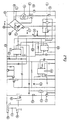
- the apparatus of the preferred embodiment is housed in a plastic case constructed in two parts, a top part 1 and a bottom part 2.
- a printed circuit board 3 containing the electronic circuit means, and display means such as meter 5, are fixed to the inside of the top part 1.
- the bottom part 2 houses a battery pack 4 which can be an alkaline battery or rechargeable nickel cadmium battery, for example.
- the battery pack 4 is connected to the printed circuit board 3 to power the electronic circuit means 55 which comprises (a) a control system, (b) a warning (timing) system and (c) a measuring system.
- the electronic circuit means can also be powered from a low voltage mains operated unit which can also act as a charger unit when rechargeable batteries are used.
- the optical testing means comprises a plastic light chamber 7 mounted adjacent the printed circuit board 3, but preferably not rigidly connected thereto.
- the light chamber 7 houses a light source such as a precision LED 8.
- the light chamber 7 also contains a light sensitive device such as a light dependent resistor cell 9.
- a removable strip gate 13 is fitted onto the light chamber 7, the LDR 9 being arranged to receive light from the precision lamp 8 after reflection from a reagent strip inserted in the strip gate 13. Since the strip gate 13 is removable, it may be replaced with different strip gates catering for different size reagent strips.
- a treated test strip is placed into gate slot 13A of the gate 13.
- the dimensions of the gate slot are such that the reagent active pad of the test strip is positioned centrally over aperture 13B.
- Light from the precision light source 8 is projected through the aperture 13B onto the activated pad of the test strip, and the reflected light (which is dependent upon the colour of the test strip) passes backthrough the aperture and is received in chamber 7A.
- the chamber 7A contains the light dependent resistor (LDR) cell 9.
- the resistance of the LDR 9 varies in proportion to the intensity of light received.
- the LDR 9 is used as the variable arm of a modified Wheatstone bridge circuit 50 in the measurement system of the electronic circuit means 55.
- the resultant inbalance in the arms of the bridge is sensed and measured by meter 5, the scale of which can be calibrated to read the appropriate units of measurement of the strip under test.
- the upper and lower meter readings are standardized or calibrated by use of a LOW reference strip (dark colour) and a HIGH reference strip (light colour).
- a reference strip is inserted in the gate slot 13A and the meter reading is adjusted to the appropriate minimum or maximum setting by means of respective variable potentiometers SET 1 (17) and SET 2 (18).
- the zero meter reading is adjusted by SET 1 while full scale deflection is adjusted by SET 2.
- potentiometer 17 (SET 1) is wired across the LDR sensing cell 9 and is not in the "C" arm of the bridge circuit as in a standard bridge circuit.
- bridge arms B and C also act as part of a potential divider chain when the meter 5 is in a stabilizer voltage measurement mode which is selected by the N/C contacts of switch 19. When the switch 19 is pressed, the N/0 contacts close, thereby placing meter 5 in a reflectance measurement mode.
- the system compensates for resistance changes of LDR 9 due to temperature variations, for example.
- the calibration procedure also compensates for long term ageing of the precision light source 8, and any foreign body that may be lodged in the aperture and affecting the intensity of the transmitted and/or reflected light beams.
- the bridge circuit 50, light source 8, and accurate timer functions of the electronic circuit means are all fed by a stabilized voltage on line 51.
- the stabilized voltage is monitored by the meter 5 when switch 19 is in the N/C position, the meter deflection being adjusted by a potentiometer 20.
- the voltage stabilizer can be of the standard type series regulator designed to maintain small differential voltages. This ensures maximum battery life when dry batteries are being used.
- a warning system comprises an LED indicator 10 and a piezo-electric buzzer 11. Also, by placing meter 5 in the voltage measurement mode, the voltage supply to electronic circuit means can be monitored, and meter 5 indicates any significant variation in the stabilized voltage.
- Timing means providing a first short timing period of approximately one minute comprises a standard type 555 timer integrated circuit 21.
- a switch 22 initiates the timing cycle, and after the timing period is completed, LED 10 turns off, thereby generating a negative pulse which is fed via capacitance 37 to the start pin of a second 555 timer 23 with a time constant of approximately 3 seconds.
- the output of IC 23 goes high and activates the piezo-electric buzzer 11 which emits an audible tone thereby signalling the end of the timing cycle.
- Pressing the switch 22 also activates a further 555 IC timer 24 which is preset to approximately 5 minutes.
- Timer 24 acts as an automatic cutout system, the 5 minute period being of sufficient time in which to carry out a single test.
- the automatic turnoff function is only operative when the device is operating from internal batteries so that battery power is conserved.
- the output of the mains adaptor is arranged to by-pass the automatic cutoff circuit via jack socket 38.
- a separate socket 39 is also provided so that the mains adaptor can be used as a battery charger when rechargeable batteries are being used.
- the final charge current can be adjusted by resistance 40.
- the operation of the automatic cutoff function is as follows. Operation of switch 22 connects the reed relay coil 25 to earth or the negative rail of the supply. Energisation of the coil 25 causes the reed contacts to close, thereby supplying power to the voltage stabilizer circuit. The stabilized voltage supply, which is preferably 4 volts, is then applied to the electronic components of the electronic circuit means.
- timer 24 When the period (5 minutes) preset on timer 24 has elapsed, the timer 24 turns off, causing transistor 42 to turn off and relay 25 to open. The device is then automatically turned off.
- the closing of switch 22 also gates, via diode 41, the timer IC 24 thereby causing it to commence timing.
- the output of the timer is connected to the base of transistor 42 ' turning it on.
- the transistor 42 then maintains a current through the relay coil 25 and holds the relay in the closed position.
- a potentiometer 26 is provided in the relay coil circuit, the coil current being variable by adjustment of the variable resistor 26. The coil current can be adjusted to allow the relay to open (thereby turning the device off) when the battery voltage falls below a predetermined value, typically 5.3 to 5.5 volts.
- the automatic cutoff circuit When the machine is connected to mains power via an adaptor (not shown) the automatic cutoff circuit is disconnected.
- the regulation of the dc supply to the electronics is such that the ac input voltage can fall by approximately one-third before the stabilizer voltage falls below its critical voltage. This is unlikely to occur under normal conditions.
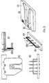
- the preferred embodiment also comprises improved means for holding the test strip in position during testing.
- a metal leaf spring 29 is provided in a gate cover 28, the spring 29 being adjusted to place a downward pressure on the test strip. This ensures that the distance from the light source 8 to the test strip surface is held constant and equal to the distance of the reference strips used in the original calibration.
- the gate cover 28 is preferably hinged for easy cleaning of the aperture 13B.
- the hinge system comprises two tabs 30 on the gate cover 28 which engage, and are rotatable in, bearing blocks 31. It has been found that in portable equipment of plastic construction, a hinged lid or door is very vulnerable to damage if the unit is dropped. In the preferred embodiment, the hinge system is such that the bearing blocks 31 are held in slots 32. Hence, if the lid is damaged it can be readily changed without the need to dismantle the whole unit. Further, the lid change operation can be performed by the owner without any disruption to the electronic circuit or calibration settings.
- the preferred embodiment also comprises display means for displaying the measured blood glucose level.
- the display means is fed with output current from the electronic circuit means and can comprise an output meter, digital display, or bargraph using LEDs.
- the output meter is a specially designed moving coil meter 5.
- the bargraph display can comprise a series of LEDs 43, the output reading being indicated by the number of LEDs which are enabled.
- the output is displayed as a coloured band of light which has the advantage of providing a quasi-digital display and yet giving analog information using colours which are easily understood by a child.
- the LEDs corresponding to high levels of blood glucose can be red LEDs while those corresponding to low levels can be green LEDs.
- the operator can determine the nature (safe or dangerous) of the blood glucose level at a glance.
- An analog readout i.e. moving coil meter or bargraph
- the meter read out is preferable as it can be repaired easily without the need for expensive or complex service equipment or specialized electronic knowledge.
- the bargraph or digital display can be used.
- a diabetic patient should test for Ketones in the urine. If a bargraph display is used, the readings above 15 mmol/I can be made to flash to thereby remind the patient to test for Ketones.
- This feature can be implemented by supplying the anodes of the LEDs reading over 15 mmol/I with a pulsating dc voltage. Oscillator IC 36 is provided for this purpose.
- the analog moving coil meter can be replaced with the bargraph display without any change to the main printed circuit board 3.
- a printed plastic screen 15 containing the numerical output readings corresponding to the particular strip used, is placed in position over the LED matrix 43.
- An integrated circuit 6 is used to interface the output of measurement means on PC board 3 to the bargraph unit.
- the integrated circuit 6 matches the balanced output of the bridge with the unbalanced input of the bargraph, which comprises comparator integrated circuits 35.
- the output from the comparators 35 is connected to a LED indicator matrix 43, which is typically a 4 x 5 matrix.
- the LEDs will light up in proportionate number to the colour of the strip being tested.
- the comparators 35 are operated in a linear mode, but the colour change of the test strip is non-linear.
- the input to output characteristic of integrated circuit 6 is made non-linear and matched to the subject test strip by means of a feedback resistor network 16.
- the resistor network 16 is a plug in unit and can be changed to suit the colour proportionality law of different strips.
- SET 1 and SET 2 are adjusted by the respective potentiometer to just light up the first and last LED.
- a mechanical or thermal display can be used.
- the mechanical display is analogous to the bargraph display except that the LEDs are replaced by pins which "pop up” on energization. The blind operator can then "read” the pin display by touch.
- the LEDs are replaced by incandescent lamps. The operator can then “read” the display by sensing the heat radiated by the enabled lamps.
- High accuracy in blood glucose readings can be achieved if there are more criteria for judging the colour of the treated strip. For example, the effect of the blood stain on a light strip and a dark strip can be compared to pin point the glucose level more accurately.
- a modified strip gate 48 is provided in which the aperture 49 is divided into two.
- the gate is designed to be used with commercially available strips of two colours so that when the strip is inserted into the gate, two treated portions of different colours 45, 46 will be positioned respectively across two apertures. This is achieved by ensuring that the divider line 47 (which divides the total aperture 49 into the two apertures) covers the boundary line between the two coloured portions of the strip.
- An eccentric adjustable strip stop 44 is provided to ensure that the treated section is properly positioned with respect to the light source, and that the boundary of the two coloured sections coincides with the dividing line 47.
- coded interchangeable strip gates 60 are provided, the gate code indicating the particular strip being used.
- the gate is physically coded by notches 61 at predetermined distances across the front of the gate as shown in Fig. 5E.
- a code reader is shown in Figs. 5B-5D and comprises a horizontal contact bar 62 and a plurality of vertical contact rods 63. When the gate 60 is inserted, the rods 63 will be bent out of contact with the bar 62, except for those rods corresponding to notches 61 in the gate. Thus, by sensing which rods are still in electrical contact with the bar 62, the code is decoded and the electronic circuit means automatically compensates for the particular strip used.
- the reference meter described above could be modified in a number of ways.
- the reflectance meters can be used for strips treated with other liquids, e.g. urine.
Claims (8)
Applications Claiming Priority (2)
| Application Number | Priority Date | Filing Date | Title |
|---|---|---|---|
| AU477/81 | 1981-08-28 | ||
| AUPF047781 | 1981-08-28 |
Publications (3)
| Publication Number | Publication Date |
|---|---|
| EP0086797A1 EP0086797A1 (fr) | 1983-08-31 |
| EP0086797A4 EP0086797A4 (fr) | 1984-03-01 |
| EP0086797B1 true EP0086797B1 (fr) | 1987-04-22 |
Family
ID=3769191
Family Applications (1)
| Application Number | Title | Priority Date | Filing Date |
|---|---|---|---|
| EP82902517A Expired EP0086797B1 (fr) | 1981-08-28 | 1982-08-26 | Instrument de mesure de la reflectance |
Country Status (4)
| Country | Link |
|---|---|
| EP (1) | EP0086797B1 (fr) |
| AU (1) | AU552675B2 (fr) |
| DE (1) | DE3276136D1 (fr) |
| WO (1) | WO1983000926A1 (fr) |
Cited By (3)
| Publication number | Priority date | Publication date | Assignee | Title |
|---|---|---|---|---|
| DE3735176A1 (de) * | 1987-10-17 | 1989-04-27 | Draegerwerk Ag | Dosimeter |
| DE8907967U1 (fr) * | 1989-06-29 | 1989-09-14 | Lre Relais + Elektronik Gmbh, 8000 Muenchen, De | |
| DE8907969U1 (fr) * | 1989-06-29 | 1989-09-14 | Lre Relais + Elektronik Gmbh, 8000 Muenchen, De |
Families Citing this family (18)
| Publication number | Priority date | Publication date | Assignee | Title |
|---|---|---|---|---|
| EP0290013B1 (fr) * | 1987-05-06 | 1996-03-13 | Fuji Photo Film Co., Ltd. | Appareil de mesure de densité et son usage |
| DE8716270U1 (fr) * | 1987-12-09 | 1988-02-18 | Lre Relais + Elektronik Gmbh, 8000 Muenchen, De | |
| DE3921391A1 (de) * | 1989-06-29 | 1991-01-10 | Lre Relais & Elektronik Gmbh | Geraet zur remissions-photometrischen analyse von fluessigkeitsproben |
| AU635314B2 (en) * | 1989-09-08 | 1993-03-18 | Terumo Kabushiki Kaisha | Measuring apparatus |
| JPH0365953U (fr) * | 1989-10-30 | 1991-06-26 | ||
| US5179288A (en) * | 1991-09-30 | 1993-01-12 | Ortho Pharmaceutical Corporation | Apparatus and method for measuring a bodily constituent |
| DE4321548A1 (de) * | 1993-06-29 | 1995-01-12 | Boehringer Mannheim Gmbh | Verfahren zum Erfassen und Auswerten analoger photometrischer Signale in einem Testträger-Analysesystem und Anordnung zur Durchführung des Verfahrens |
| JP2001522043A (ja) | 1997-10-31 | 2001-11-13 | テクニカル ケミカルズ アンド プロダクツ、 インコーポレイテッド | 反射率計 |
| US6239445B1 (en) | 1999-03-01 | 2001-05-29 | Bayer Corporation | Optical inspection apparatus with removable inserts |
| US7577469B1 (en) | 1999-03-11 | 2009-08-18 | Jack L. Aronowitz | Noninvasive transdermal systems for detecting an analyte in a biological fluid and methods |
| US6525330B2 (en) * | 2001-02-28 | 2003-02-25 | Home Diagnostics, Inc. | Method of strip insertion detection |
| US6541266B2 (en) * | 2001-02-28 | 2003-04-01 | Home Diagnostics, Inc. | Method for determining concentration of an analyte in a test strip |
| US7488601B2 (en) | 2003-06-20 | 2009-02-10 | Roche Diagnostic Operations, Inc. | System and method for determining an abused sensor during analyte measurement |
| RU2006132051A (ru) | 2004-02-06 | 2008-03-20 | БАЙЕР ХЕЛТКЭР ЭлЭлСи (US) | Окисляемые соединения в качестве внутреннего стандарта для биосенсоров и способ их применения |
| US7569126B2 (en) | 2004-06-18 | 2009-08-04 | Roche Diagnostics Operations, Inc. | System and method for quality assurance of a biosensor test strip |
| AR054851A1 (es) | 2005-07-20 | 2007-07-18 | Bayer Healthcare Llc | Amperometria regulada |
| US8404100B2 (en) | 2005-09-30 | 2013-03-26 | Bayer Healthcare Llc | Gated voltammetry |
| WO2009076302A1 (fr) | 2007-12-10 | 2009-06-18 | Bayer Healthcare Llc | Marqueurs de contrôle pour la détection automatique d'une solution de contrôle et procédés d'utilisation |
Citations (1)
| Publication number | Priority date | Publication date | Assignee | Title |
|---|---|---|---|---|
| US3907503A (en) * | 1974-01-21 | 1975-09-23 | Miles Lab | Test system |
Family Cites Families (3)
| Publication number | Priority date | Publication date | Assignee | Title |
|---|---|---|---|---|
| US3604815A (en) * | 1968-04-22 | 1971-09-14 | Miles Lab | Reflectance meter |
| GB1598086A (en) * | 1977-12-22 | 1981-09-16 | Medistron Ltd | Reflectometers |
| DE3026439A1 (de) * | 1980-07-10 | 1982-02-11 | Sigma Instrumente GmbH, 1000 Berlin | Photometer, insbesondere reflexionsphotometer, fuer diagnosestreifen |
-
1982
- 1982-08-26 DE DE8282902517T patent/DE3276136D1/de not_active Expired
- 1982-08-26 EP EP82902517A patent/EP0086797B1/fr not_active Expired
- 1982-08-26 WO PCT/AU1982/000141 patent/WO1983000926A1/fr active IP Right Grant
- 1982-08-26 AU AU88223/82A patent/AU552675B2/en not_active Ceased
Patent Citations (1)
| Publication number | Priority date | Publication date | Assignee | Title |
|---|---|---|---|---|
| US3907503A (en) * | 1974-01-21 | 1975-09-23 | Miles Lab | Test system |
Cited By (3)
| Publication number | Priority date | Publication date | Assignee | Title |
|---|---|---|---|---|
| DE3735176A1 (de) * | 1987-10-17 | 1989-04-27 | Draegerwerk Ag | Dosimeter |
| DE8907967U1 (fr) * | 1989-06-29 | 1989-09-14 | Lre Relais + Elektronik Gmbh, 8000 Muenchen, De | |
| DE8907969U1 (fr) * | 1989-06-29 | 1989-09-14 | Lre Relais + Elektronik Gmbh, 8000 Muenchen, De |
Also Published As
| Publication number | Publication date |
|---|---|
| DE3276136D1 (en) | 1987-05-27 |
| AU8822382A (en) | 1983-03-08 |
| WO1983000926A1 (fr) | 1983-03-17 |
| EP0086797A4 (fr) | 1984-03-01 |
| AU552675B2 (en) | 1986-06-12 |
| EP0086797A1 (fr) | 1983-08-31 |
Similar Documents
| Publication | Publication Date | Title |
|---|---|---|
| EP0086797B1 (fr) | Instrument de mesure de la reflectance | |
| US4397725A (en) | Apparatus for measuring electrochemical activity | |
| US7220597B2 (en) | Assay test device and method of making same | |
| US7214542B2 (en) | Method of processing assay test results | |
| CA1239477A (fr) | Thermometre electronique a temporisation fixee de reaction | |
| US5277870A (en) | Blood glucose reflectance meter including a null prompting means and a device for providing a constant brightness light | |
| AU622293B2 (en) | A compact semi-programmable device for reading reagent test strips and method relating thereto | |
| EP0637808B1 (fr) | Système de mémoire sans touches pour un dispositif de mesure électronique | |
| EP0764469B1 (fr) | Méthode et dispositif et dispositif pour l'enregistrement d'événements prédéterminés par un biocapteur | |
| CA2300090C (fr) | Dispositif de verification de systemes d'essais clinique optique | |
| US4436610A (en) | Apparatus for measuring electrochemical activity | |
| US4069716A (en) | Apparatus and method for use in determining conditions related to a plant | |
| US4268173A (en) | Reflectometers | |
| US4336121A (en) | Apparatus for measuring electrochemical activity | |
| JP2002531827A (ja) | 改良校正及び通信プロセスを有するアナライト検査器具 | |
| US4124301A (en) | Device for measuring light transmitted through a material | |
| US6222371B1 (en) | Hand-held fluid tester for process fluids | |
| CA1066913A (fr) | Thermoson des electroniques pour fins medicales | |
| JP3738357B2 (ja) | 携帯型検体分析装置 | |
| US3476516A (en) | Gas analyzer | |
| CA1067717A (fr) | Thermometres cliniques transportables a senseurs electroniques | |
| JP4734495B2 (ja) | 分析検査結果を処理するための方法及び装置 | |
| US3427537A (en) | Direct measuring moisture apparatus including replaceable scale dials | |
| CA1333230C (fr) | Illuminateur pour refractometre | |
| EP1037183B1 (fr) | Dispositif d'alarme pour la détection de gaz |
Legal Events
| Date | Code | Title | Description |
|---|---|---|---|
| PUAI | Public reference made under article 153(3) epc to a published international application that has entered the european phase |
Free format text: ORIGINAL CODE: 0009012 |
|
| AK | Designated contracting states |
Designated state(s): DE GB SE |
|
| 17P | Request for examination filed |
Effective date: 19831013 |
|
| R17P | Request for examination filed (corrected) |
Effective date: 19830913 |
|
| GRAA | (expected) grant |
Free format text: ORIGINAL CODE: 0009210 |
|
| AK | Designated contracting states |
Kind code of ref document: B1 Designated state(s): DE GB SE |
|
| PG25 | Lapsed in a contracting state [announced via postgrant information from national office to epo] |
Ref country code: SE Effective date: 19870430 |
|
| REF | Corresponds to: |
Ref document number: 3276136 Country of ref document: DE Date of ref document: 19870527 |
|
| PLBE | No opposition filed within time limit |
Free format text: ORIGINAL CODE: 0009261 |
|
| STAA | Information on the status of an ep patent application or granted ep patent |
Free format text: STATUS: NO OPPOSITION FILED WITHIN TIME LIMIT |
|
| 26N | No opposition filed | ||
| PGFP | Annual fee paid to national office [announced via postgrant information from national office to epo] |
Ref country code: GB Payment date: 19890831 Year of fee payment: 8 |
|
| PGFP | Annual fee paid to national office [announced via postgrant information from national office to epo] |
Ref country code: DE Payment date: 19891017 Year of fee payment: 8 |
|
| PG25 | Lapsed in a contracting state [announced via postgrant information from national office to epo] |
Ref country code: GB Effective date: 19900826 |
|
| GBPC | Gb: european patent ceased through non-payment of renewal fee | ||
| PG25 | Lapsed in a contracting state [announced via postgrant information from national office to epo] |
Ref country code: DE Effective date: 19910501 |