EP0086617A2 - Remotely controllable lockable container for safekeeping articles - Google Patents
Remotely controllable lockable container for safekeeping articles Download PDFInfo
- Publication number
- EP0086617A2 EP0086617A2 EP83300612A EP83300612A EP0086617A2 EP 0086617 A2 EP0086617 A2 EP 0086617A2 EP 83300612 A EP83300612 A EP 83300612A EP 83300612 A EP83300612 A EP 83300612A EP 0086617 A2 EP0086617 A2 EP 0086617A2
- Authority
- EP
- European Patent Office
- Prior art keywords
- container
- key
- electrical
- lock
- control device
- Prior art date
- Legal status (The legal status is an assumption and is not a legal conclusion. Google has not performed a legal analysis and makes no representation as to the accuracy of the status listed.)
- Granted
Links
Images
Classifications
-
- G—PHYSICS
- G08—SIGNALLING
- G08B—SIGNALLING OR CALLING SYSTEMS; ORDER TELEGRAPHS; ALARM SYSTEMS
- G08B13/00—Burglar, theft or intruder alarms
- G08B13/02—Mechanical actuation
-
- E—FIXED CONSTRUCTIONS
- E05—LOCKS; KEYS; WINDOW OR DOOR FITTINGS; SAFES
- E05B—LOCKS; ACCESSORIES THEREFOR; HANDCUFFS
- E05B19/00—Keys; Accessories therefor
- E05B19/0005—Key safes
-
- G—PHYSICS
- G08—SIGNALLING
- G08B—SIGNALLING OR CALLING SYSTEMS; ORDER TELEGRAPHS; ALARM SYSTEMS
- G08B29/00—Checking or monitoring of signalling or alarm systems; Prevention or correction of operating errors, e.g. preventing unauthorised operation
Abstract
Description
- The invention relates to a remotely controllable lockable container for safekeeping articles.
- Lockable containers of this kind are known, in particular, in the form of so-called fire-brigade key boxes which contain a master key which enables a fire brigade or other supervising authority to gain access to the associated premises in the event of a fire alarm or burglar alarm occurring. Key boxes of this kind have proved necessary because fire brigades and other supervising organisations otherwise have to. keep ready for use a great number of keys going far beyond that which can be reasonably managed with the amount of property to be supervised. Fire-brigade key boxes are accordingly used to hold ready the necessary key or keys at the entry to a building or its grounds. Securing such keys against mis-use by break-in or loss requires effective securing means for such key boxes, however.
- Fire brigade key boxes of known kind are accordingly already equipped with an outer door which normally can only be opened electrically and which can only be unlocked remotely, e.g. from a fire-alarm centre. For this purpose, such a key box contains a control switch which monitors the locking of its outer door and indicates when the door is opened. The box may further possess monitoring devices for indicating the condition of its outer walls, thereby to secure the box against break-in without warning. Furthermore, it must be arranged that, in the event of permissible, remote-controlled unlocking of the outer door of the box, no alarm is set off. In respect of the wiring for the known fire brigade key boxes, therefore, there is a problem in securing the wiring against sabotage or mis-use and heavy expense on cabling is necessary, even if most of the electrical parts are disposed in the security of the associated fire-alarm centre - as already proposed.
- It is an object of the present invention to achieve a greater degree of security and reliability for remotely controllable, lockable containers for safe keeping articles with lesser expense.
- According to the present invention, there is provided a remotely controllable, lockable container for safekeeping articles or equipment against unauthorised use comprising at least one door having a lock which can be unlocked by electrical signals to be conveyed over long-distance electrical conductors and which can be monitored via electrical signals as to its locked or unlocked state, and an electronic control device for comparing the signals in order to avoid false alarms, the control device being disposed in the container.
- Since the control device for comparing the electrical signals is positioned in the normally locked container, the electrical conductors associated with the control device are also protected from manipulation or sabotage. Furthermore, a reduced number of electrical conductors are required, emanating from the box, because it is no longer necessary to transmit the individual monitoring signals to a remote centre to be combined and/or compared as required. Instead, it is necessary to transmit only a single alarm signal from the container to the fire-alarm or security centre and a single unlocking signal from the centre to the container for authorised opening of the container.
- Although the main use of a container of the present invention is to make keys available, it is understood that a container in accordance with the invention may perform a large number of other tasks, for example, to prevent the unauthorised use of switches or other actuating equipment.
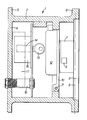
- A specific embodiment of the present invention will now be described by way of example, and not by way of limitation, with reference to the accompanying diagrammatic drawing which shows, in cross-section, and in locked condition, a fire brigade key box in accordance with the present invention.
- The key box illustrated in the drawing and designated as a whole by the reference numeral 1 comprises a housing 2 having a
door 3.. In the diagrammatic illustration, constructional details are omitted but as may be seen, the basic shape of the housing 2 is particularly suitable for installation in a wall with a surrounding anchoring flange 5 projecting from its flat rear wall 4 to be embedded in the wall and asimilar flange 6 surrounding thedoor 3, which may overlie the front surface of the wall to provide a satisfactory seal and .lie flush with the wall facing and at the same time guard the fabric of the wall adjacent the side walls of the housing, and the side walls of the housing itself, against tampering. - The housing walls themselves and also the
outer door 3 contain narrowly spaced apart electrical conductors (not shown) for monitoring any penetration or breaking through of the walls or the door. - The
outer door 3 has, at the inside, an electrically operable lock 7 having a bolt 8 so that the front of the key box 1 has no keyhole enabling the door lock to be picked or more readily forced. The unlocking of the electrically operable lock 7 is usually signalled from a remote control centre, such as a fire-alarm centre or security centre. The unlocked door can then be swung aside about avertical axis 9 to gain access to a second,inner door 10. Theinner door 10 situated behind theouter door 3 is hinged to swing outwards about a horizontal,bottom axis 11, as soon as it, too, is unlocked. In the present case, theinner door 10 has amechanical lock 12 which can be unlocked by means of a fire brigade master key. This master key would be designed to fit a plurality oflocks 12 likely to require to be operated by the fire brigade. - With the opening'of the
inner door 10, the article to be secured against mis-use, in this example akey 13 of opening all the doors of the house, becomes accessible. According to some fire insurance guidelines already in existence, such a key 13 must always be monitored for its presence in the fire brigade box. - In the present example, such monitoring is effected in a particularly reliable manner in as far as the
key 13 is fitted in alock cylinder 14 of a cylinder lock which is operable by the key to actuate a surroundingcontrol switching device 15. Thus, there is a check that only the proper key can be fitted and has actually been inserted in the box and is ready in case of need. - The fire brigade security box 1 being described contains various electrical monitoring and control devices such as the electrically operable lock 7, the electrical conductors monitoring the security of the housing walls and outer door and also control switches (not shown) in the door and monitoring the opening and closing of the outer door and the operation of the lock 7. To these monitoring devices for the box, which can be supplemented and extended if necessary, there must be added the monitoring of the presence of the
key 13. - The electrical signals, in total, have to be combined, compared and/or rationalized with one another. For example, when the
door 3 is unlocked, it must be assured that no false alarm is set off or that no false alarm is given by the actual opening of the door. On the other hand, when thedoor 3 is closed prior to being locked, a combination of the door monitoring signals with the signal of theswitch device 15 has to be effected to ensure that theouter door 3 cannot be locked or correctly monitored as being locked unless thecorrect key 13 has been inserted and thecylinder lock 14 operated. The combination, comparison and/or rationalization of the various electrical signals for the fire brigade key box could be effected in the associated fire-alarm centre. The electrical conductors (not shown) carrying the signals would be taken through acable duct 16 opening through the rear wall 4 of the housing 2, i.e. to the rear of, or in, the building wall. - In this case, however, an extensive array of conductors is required emanating from the fire brigade key box which are expensive to secure and protect.
- Instead, therefore, the key box houses a
control device 17 disposed inside the key box. Thecontrol device 17 is indicated by chain lines and lies close to the rear wall 4 of the key box. Thecontrol device 17 combines the electrical monitoring and control functions of the key box with one another in the required manner so that the number of electrical conductors which have to be taken out through thecable duct 16 are reduced to a minimum. The arrangement of the control device in the locked key box itself also offers the greatest possible security against sabotage or manipulation, because the electrical or electronic components associated with the control and supervision of the key box themselves and also a large proportion of the associated wiring are secured in safe keeping within the box. - It is to be understood that the embodiment of the present invention described with reference to the accompanying drawing may be modified to safeguard other objects and articles against mis-use, in which case the monitoring regime would be modified to suit the article or object concerned. The
control device 17 might well become more complex for a more complex supervising task in which case greater benefits are obtained in that thecontrol device 17 is disposed in the locked container 1 itself and so, is also secured in itself.
Claims (4)
Priority Applications (1)
| Application Number | Priority Date | Filing Date | Title |
|---|---|---|---|
| AT83300612T ATE26759T1 (en) | 1982-02-11 | 1983-02-08 | REMOTE CONTROLLED LOCKABLE CONTAINER TO PROTECT ITEMS. |
Applications Claiming Priority (2)
| Application Number | Priority Date | Filing Date | Title |
|---|---|---|---|
| DE3204763 | 1982-02-11 | ||
| DE19823204763 DE3204763A1 (en) | 1982-02-11 | 1982-02-11 | SEALING CONTAINER |
Publications (3)
| Publication Number | Publication Date |
|---|---|
| EP0086617A2 true EP0086617A2 (en) | 1983-08-24 |
| EP0086617A3 EP0086617A3 (en) | 1984-11-07 |
| EP0086617B1 EP0086617B1 (en) | 1987-04-22 |
Family
ID=6155390
Family Applications (1)
| Application Number | Title | Priority Date | Filing Date |
|---|---|---|---|
| EP83300612A Expired EP0086617B1 (en) | 1982-02-11 | 1983-02-08 | Remotely controllable lockable container for safekeeping articles |
Country Status (6)
| Country | Link |
|---|---|
| EP (1) | EP0086617B1 (en) |
| AT (2) | AT379200B (en) |
| AU (1) | AU558809B2 (en) |
| DE (2) | DE3204763A1 (en) |
| DK (1) | DK160625C (en) |
| NO (1) | NO155408C (en) |
Cited By (9)
| Publication number | Priority date | Publication date | Assignee | Title |
|---|---|---|---|---|
| FR2630563A1 (en) * | 1988-04-25 | 1989-10-27 | Warfman Daniel | SAFETY BOX, IN PARTICULAR FOR THE MANAGEMENT OF ACCESS MEANS FOR CONTROLLED USE |
| EP0668421A1 (en) * | 1994-02-21 | 1995-08-23 | Schloss- und Beschlägefabrik AG | Safe for the containment of object keys |
| FR2741103A1 (en) * | 1995-11-15 | 1997-05-16 | Brink S Sa | Electronic control system for locks of cash storage safes in cash dispenser |
| EP1088958A3 (en) * | 1999-09-28 | 2003-01-22 | Siemens Aktiengesellschaft | Key-safe and system for allowing access to a building for a service provider |
| EP1304443A3 (en) * | 1998-10-19 | 2004-11-03 | Helbling & Co. AG | Tubular key safe |
| US7042334B2 (en) | 2003-01-31 | 2006-05-09 | General Electric Company | Methods for managing access to physical assets |
| WO2006102895A1 (en) * | 2005-03-30 | 2006-10-05 | Birepo Aps | A key box for locked storage of coded access items - such as access cards and keys |
| US7123127B2 (en) | 2003-01-31 | 2006-10-17 | General Electric Company | System for managing physical assets |
| US9670694B2 (en) | 2007-04-12 | 2017-06-06 | Utc Fire & Security Americas Corporation, Inc. | Restricted range lockbox, access device and methods |
Families Citing this family (5)
| Publication number | Priority date | Publication date | Assignee | Title |
|---|---|---|---|---|
| ES2587062T3 (en) * | 2008-11-18 | 2016-10-20 | Inventio Ag | Building access system |
| CN105370146A (en) * | 2015-12-25 | 2016-03-02 | 海宁市引领知识产权咨询服务有限公司 | Novel mechano-electronic double-safety protecting box |
| DK3339129T3 (en) | 2016-12-22 | 2021-09-20 | Bombardier Transp Gmbh | RAIL VEHICLE AND METHOD OF OPERATING A RAIL VEHICLE |
| DE202019104559U1 (en) * | 2019-08-20 | 2020-11-30 | Kruse Sicherheitssysteme Gmbh & Co. Kg | Key deposit |
| CN112922493A (en) * | 2021-03-04 | 2021-06-08 | 南宁市广迪自动化科技有限公司 | But safe deposit box of remote monitoring |
Citations (3)
| Publication number | Priority date | Publication date | Assignee | Title |
|---|---|---|---|---|
| CA931430A (en) * | 1971-02-15 | 1973-08-07 | Desaulniers Jacques | Remote controlled strong box assembly and latch therefor |
| DE2902193A1 (en) * | 1979-01-20 | 1980-07-31 | Frentrup Adolf | Electromechanically protected lock with magnetic bolt - which prevents unauthorised opening of lock even with proper key and includes lockable key stowage |
| EP0021670A1 (en) * | 1979-06-07 | 1981-01-07 | Bjoern Lyng | Code type lock especially for safes |
-
1982
- 1982-02-11 DE DE19823204763 patent/DE3204763A1/en not_active Withdrawn
-
1983
- 1983-02-03 AT AT0037783A patent/AT379200B/en not_active IP Right Cessation
- 1983-02-08 AT AT83300612T patent/ATE26759T1/en not_active IP Right Cessation
- 1983-02-08 EP EP83300612A patent/EP0086617B1/en not_active Expired
- 1983-02-08 AU AU11219/83A patent/AU558809B2/en not_active Ceased
- 1983-02-08 DE DE8383300612T patent/DE3371131D1/en not_active Expired
- 1983-02-10 DK DK058283A patent/DK160625C/en not_active IP Right Cessation
- 1983-02-10 NO NO830448A patent/NO155408C/en unknown
Patent Citations (3)
| Publication number | Priority date | Publication date | Assignee | Title |
|---|---|---|---|---|
| CA931430A (en) * | 1971-02-15 | 1973-08-07 | Desaulniers Jacques | Remote controlled strong box assembly and latch therefor |
| DE2902193A1 (en) * | 1979-01-20 | 1980-07-31 | Frentrup Adolf | Electromechanically protected lock with magnetic bolt - which prevents unauthorised opening of lock even with proper key and includes lockable key stowage |
| EP0021670A1 (en) * | 1979-06-07 | 1981-01-07 | Bjoern Lyng | Code type lock especially for safes |
Cited By (13)
| Publication number | Priority date | Publication date | Assignee | Title |
|---|---|---|---|---|
| FR2630563A1 (en) * | 1988-04-25 | 1989-10-27 | Warfman Daniel | SAFETY BOX, IN PARTICULAR FOR THE MANAGEMENT OF ACCESS MEANS FOR CONTROLLED USE |
| EP0340078A1 (en) * | 1988-04-25 | 1989-11-02 | Prestations Européennes de Sécurité s.a.r.l. | Safe, particularly for accounting access means or other objects for monitored usage |
| US4967576A (en) * | 1988-04-25 | 1990-11-06 | Daniel Warfman | Security cabinet, in particular for the management of means of access or other controlled-use objects |
| EP0668421A1 (en) * | 1994-02-21 | 1995-08-23 | Schloss- und Beschlägefabrik AG | Safe for the containment of object keys |
| FR2741103A1 (en) * | 1995-11-15 | 1997-05-16 | Brink S Sa | Electronic control system for locks of cash storage safes in cash dispenser |
| EP1304443A3 (en) * | 1998-10-19 | 2004-11-03 | Helbling & Co. AG | Tubular key safe |
| EP1088958A3 (en) * | 1999-09-28 | 2003-01-22 | Siemens Aktiengesellschaft | Key-safe and system for allowing access to a building for a service provider |
| US7042334B2 (en) | 2003-01-31 | 2006-05-09 | General Electric Company | Methods for managing access to physical assets |
| US7123127B2 (en) | 2003-01-31 | 2006-10-17 | General Electric Company | System for managing physical assets |
| WO2006102895A1 (en) * | 2005-03-30 | 2006-10-05 | Birepo Aps | A key box for locked storage of coded access items - such as access cards and keys |
| EP1863987B1 (en) | 2005-03-30 | 2017-03-29 | Birepo APS | A key box for locked storage of coded access items - such as access cards and keys |
| NO341487B1 (en) * | 2005-03-30 | 2017-11-27 | Birepo Aps | Procedure for mounting a key box, as well as a key box for locked storage of encoded access objects |
| US9670694B2 (en) | 2007-04-12 | 2017-06-06 | Utc Fire & Security Americas Corporation, Inc. | Restricted range lockbox, access device and methods |
Also Published As
| Publication number | Publication date |
|---|---|
| EP0086617A3 (en) | 1984-11-07 |
| ATE26759T1 (en) | 1987-05-15 |
| ATA37783A (en) | 1985-04-15 |
| NO155408C (en) | 1987-03-25 |
| DE3371131D1 (en) | 1987-05-27 |
| NO155408B (en) | 1986-12-15 |
| AT379200B (en) | 1985-11-25 |
| EP0086617B1 (en) | 1987-04-22 |
| AU558809B2 (en) | 1987-02-12 |
| DK160625C (en) | 1991-09-02 |
| DK58283A (en) | 1983-08-12 |
| DK160625B (en) | 1991-04-02 |
| DK58283D0 (en) | 1983-02-10 |
| NO830448L (en) | 1983-08-12 |
| DE3204763A1 (en) | 1983-08-18 |
| AU1121983A (en) | 1983-08-18 |
Similar Documents
| Publication | Publication Date | Title |
|---|---|---|
| EP0086617B1 (en) | Remotely controllable lockable container for safekeeping articles | |
| US5486812A (en) | Security arrangement | |
| US6310549B1 (en) | Wireless security system | |
| US7116224B2 (en) | Method and apparatus for securing firearms and other valuables in an alarm protected facility | |
| GB2286423A (en) | Security system | |
| US5764729A (en) | Local alarm system tamper protection device with dual conduits | |
| EP3581740B1 (en) | Security lock for trailer cargo compartment | |
| US20180279456A1 (en) | System and method for two-level protection for accessing closed and semi-closed enclosures | |
| NZ203866A (en) | Remote unlocking safe:electrical control housed in safe | |
| PL181796B1 (en) | Electronic access controlling and safeguarding device | |
| KR102113881B1 (en) | Door Look System having Improved Crime Prevention Function Fireproof Function | |
| US4413492A (en) | Deadbolt lock protector | |
| EP3942128A1 (en) | A smart lock for operating a door lock and an alarm installation with such smart lock and a central unit | |
| GB2354286A (en) | A secure receptacle | |
| GB2280709A (en) | Building security system | |
| JP2548627Y2 (en) | Door locking device | |
| US1174125A (en) | Electrical burglar-alarm. | |
| JPH02108779A (en) | Locker with monitoring function | |
| UA151683U (en) | Method of placing the security alarm sensor | |
| WO2007100235A1 (en) | Locking mechanism protection | |
| NL9000754A (en) | Radio controlled key safe for security patrol vehicle - allows patrol access to keys only when two pass-words are supplied | |
| KR20080069785A (en) | Eqbox |
Legal Events
| Date | Code | Title | Description |
|---|---|---|---|
| PUAI | Public reference made under article 153(3) epc to a published international application that has entered the european phase |
Free format text: ORIGINAL CODE: 0009012 |
|
| AK | Designated contracting states |
Designated state(s): AT BE CH DE FR GB IT LI LU NL SE |
|
| PUAL | Search report despatched |
Free format text: ORIGINAL CODE: 0009013 |
|
| AK | Designated contracting states |
Designated state(s): AT BE CH DE FR GB IT LI LU NL SE |
|
| 17P | Request for examination filed |
Effective date: 19841227 |
|
| 17Q | First examination report despatched |
Effective date: 19860430 |
|
| ITF | It: translation for a ep patent filed |
Owner name: BARZANO' E ZANARDO MILANO S.P.A. |
|
| GRAA | (expected) grant |
Free format text: ORIGINAL CODE: 0009210 |
|
| AK | Designated contracting states |
Kind code of ref document: B1 Designated state(s): AT BE CH DE FR GB IT LI LU NL SE |
|
| REF | Corresponds to: |
Ref document number: 26759 Country of ref document: AT Date of ref document: 19870515 Kind code of ref document: T |
|
| REF | Corresponds to: |
Ref document number: 3371131 Country of ref document: DE Date of ref document: 19870527 |
|
| ET | Fr: translation filed | ||
| PLBE | No opposition filed within time limit |
Free format text: ORIGINAL CODE: 0009261 |
|
| STAA | Information on the status of an ep patent application or granted ep patent |
Free format text: STATUS: NO OPPOSITION FILED WITHIN TIME LIMIT |
|
| 26N | No opposition filed | ||
| ITTA | It: last paid annual fee | ||
| PGFP | Annual fee paid to national office [announced via postgrant information from national office to epo] |
Ref country code: SE Payment date: 19930208 Year of fee payment: 11 Ref country code: GB Payment date: 19930208 Year of fee payment: 11 |
|
| PGFP | Annual fee paid to national office [announced via postgrant information from national office to epo] |
Ref country code: BE Payment date: 19930216 Year of fee payment: 11 |
|
| PGFP | Annual fee paid to national office [announced via postgrant information from national office to epo] |
Ref country code: LU Payment date: 19930218 Year of fee payment: 11 |
|
| PGFP | Annual fee paid to national office [announced via postgrant information from national office to epo] |
Ref country code: FR Payment date: 19930219 Year of fee payment: 11 |
|
| PGFP | Annual fee paid to national office [announced via postgrant information from national office to epo] |
Ref country code: CH Payment date: 19930222 Year of fee payment: 11 |
|
| PGFP | Annual fee paid to national office [announced via postgrant information from national office to epo] |
Ref country code: AT Payment date: 19930226 Year of fee payment: 11 |
|
| EPTA | Lu: last paid annual fee | ||
| PG25 | Lapsed in a contracting state [announced via postgrant information from national office to epo] |
Ref country code: LU Free format text: LAPSE BECAUSE OF NON-PAYMENT OF DUE FEES Effective date: 19940208 Ref country code: GB Effective date: 19940208 Ref country code: AT Effective date: 19940208 |
|
| PG25 | Lapsed in a contracting state [announced via postgrant information from national office to epo] |
Ref country code: SE Effective date: 19940209 |
|
| PG25 | Lapsed in a contracting state [announced via postgrant information from national office to epo] |
Ref country code: LI Effective date: 19940228 Ref country code: CH Effective date: 19940228 Ref country code: BE Effective date: 19940228 |
|
| BERE | Be: lapsed |
Owner name: COLT INTERNATIONAL HOLDINGS A.G. Effective date: 19940228 |
|
| GBPC | Gb: european patent ceased through non-payment of renewal fee |
Effective date: 19940208 |
|
| PG25 | Lapsed in a contracting state [announced via postgrant information from national office to epo] |
Ref country code: FR Effective date: 19941031 |
|
| REG | Reference to a national code |
Ref country code: CH Ref legal event code: PL |
|
| REG | Reference to a national code |
Ref country code: FR Ref legal event code: ST |
|
| EUG | Se: european patent has lapsed |
Ref document number: 83300612.5 Effective date: 19940910 |
|
| PGFP | Annual fee paid to national office [announced via postgrant information from national office to epo] |
Ref country code: NL Payment date: 19970225 Year of fee payment: 15 |
|
| PGFP | Annual fee paid to national office [announced via postgrant information from national office to epo] |
Ref country code: DE Payment date: 19970303 Year of fee payment: 15 |
|
| PG25 | Lapsed in a contracting state [announced via postgrant information from national office to epo] |
Ref country code: NL Free format text: LAPSE BECAUSE OF NON-PAYMENT OF DUE FEES Effective date: 19980901 |
|
| NLV4 | Nl: lapsed or anulled due to non-payment of the annual fee |
Effective date: 19980901 |
|
| PG25 | Lapsed in a contracting state [announced via postgrant information from national office to epo] |
Ref country code: DE Free format text: LAPSE BECAUSE OF NON-PAYMENT OF DUE FEES Effective date: 19981103 |