EP0086597A2 - Elektroosmotischer Tintendruckkopf - Google Patents
Elektroosmotischer Tintendruckkopf Download PDFInfo
- Publication number
- EP0086597A2 EP0086597A2 EP83300534A EP83300534A EP0086597A2 EP 0086597 A2 EP0086597 A2 EP 0086597A2 EP 83300534 A EP83300534 A EP 83300534A EP 83300534 A EP83300534 A EP 83300534A EP 0086597 A2 EP0086597 A2 EP 0086597A2
- Authority
- EP
- European Patent Office
- Prior art keywords
- ink
- electrodes
- electrode
- porous member
- printer head
- Prior art date
- Legal status (The legal status is an assumption and is not a legal conclusion. Google has not performed a legal analysis and makes no representation as to the accuracy of the status listed.)
- Granted
Links
Images

Classifications
-
- B—PERFORMING OPERATIONS; TRANSPORTING
- B41—PRINTING; LINING MACHINES; TYPEWRITERS; STAMPS
- B41J—TYPEWRITERS; SELECTIVE PRINTING MECHANISMS, i.e. MECHANISMS PRINTING OTHERWISE THAN FROM A FORME; CORRECTION OF TYPOGRAPHICAL ERRORS
- B41J2/00—Typewriters or selective printing mechanisms characterised by the printing or marking process for which they are designed
- B41J2/005—Typewriters or selective printing mechanisms characterised by the printing or marking process for which they are designed characterised by bringing liquid or particles selectively into contact with a printing material
- B41J2/01—Ink jet
- B41J2/015—Ink jet characterised by the jet generation process
- B41J2/04—Ink jet characterised by the jet generation process generating single droplets or particles on demand
-
- G—PHYSICS
- G01—MEASURING; TESTING
- G01D—MEASURING NOT SPECIALLY ADAPTED FOR A SPECIFIC VARIABLE; ARRANGEMENTS FOR MEASURING TWO OR MORE VARIABLES NOT COVERED IN A SINGLE OTHER SUBCLASS; TARIFF METERING APPARATUS; MEASURING OR TESTING NOT OTHERWISE PROVIDED FOR
- G01D15/00—Component parts of recorders for measuring arrangements not specially adapted for a specific variable
- G01D15/16—Recording elements transferring recording material, e.g. ink, to the recording surface
- G01D15/18—Nozzles emitting recording material
Definitions
- the present invention relates to an ink printer head utilizing the electroosmotic movement of the liquid in a system comprising a porous member sandwiched between opposed electrodes.
- a known electroosmotic ink printer head as shown and described in European Patent Applications Nos. 81.107382 and 82.105894, comprises a plurality of first electrodes successively arranged on a surface of a dielectric support, a second, liquid-permeable electrode and a porous member sandwiched between the first and second electrode. Means are provided,to cause ink to permeate through the second electrode to the porous member. Potentials of recording signals are applied to the first electrodes with respect to the second electrode to cause the ink in the porous member to electroosmotically migrate along the paths of first electrodes to the front edge of the support adjacent to which a recording medium is located.
- the ink employed in the printer has a tendency to spontaneously leak through the porous member and wet the portions of the support's front edge where the first electrodes are not provided. This stains the edge portions of the recording medium.
- an object of the present invention is to provide an electroosmotic ink printer head which is free from the wetting problem.
- the invention contemplates the provision of an additional electrode adjacent to the otherwise wet area of a dielectric support and the application of a potential thereto with respect to the second electrode to cause the ink in the porous member to electroosmotically move in a direction from the additional electrode toward the second electrode. This causes the ink in the otherwise wet area to be pulled from the front edge of the support.
- the electroosmotic ink printer head of the invention comprises a dielectric support having a surface defined by front and rear sides and a pair of opposite ends.
- An array of first electrodes is provided on said surface extending rearward from the front side of the support.
- a porous member is provided in overlying relation with the first electrodes in contact with said surface.
- On the porous member is a second, liquid-permeable electrode on which is provided a means for supplying ink thereto to allow it to permeate therethrough to the porous member.
- a third electrode is located adjacent to each end of the array of the first electrodes and to the front side of the support.
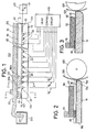
- the printer head 100 comprises a dielectric support 10 of rectangular shape formed typically of sodium borosilicate glass.
- the dielectric support 10 has a front side wall 10a, a rear side wall lOb, and a pair of opposite end walls 10c and lOd.
- On the upper surface of the dielectric support 10 is formed an array of successively arranged parallel strip electrodes 20 which extend rearward from the front side wall 10a of the dielectric support.
- the electrodes 20 are coupled individually to a known head control circuit 400 which drives them in a manner as disclosed in the aforesaid Copending applications.
- the electrodes 20 are impressed with modulated voltages to form a print line on a recording sheet 500 engaging a platen 600, the sheet being successively advanced by the width of a line by a paper feeder, not shown.
- Each of the electrodes 20 preferably has a U-shaped cross-section. This is achieved by depositing metal on the inner walls and bottom of a groove formed on the upper surface of the dielectric support 10 to a depth of 20 to 70 micrometers. Three to eight such grooves are formed per millimeter within an intermediate area between the opposite end walls 10c and 10d as by etching or machining to leave space in each end portion of the support 10 for reasons of manufacture.
- the electrodes 20 and 30 are made of a nonporous metal which may be formed by vacuum depositing chrome or the like to a thickness of 0.1 to 0.3 micrometers as a precoat and subsequently by vacuum depositing gold to a thickness of 1 micrometer or by electroplating.
- a block of porous material 40 is secured to the upper surface of the dielectric support 10 to define electroosmotic liquid passages with the grooved electrodes 20.
- the porous member 40 has an average pore size such that it permits the ink employed in the invention to permeate therethrough in the direction of thickness.
- the porous member 40 is a microporous membrane filter comprising cellulose acetate having a porosity of 60% to 80% with an average pore size of 0.1 to 8 micrometers and has a thickness of 20 to 200 micrometers.
- the material of the porous member 40 may be selected from plastic materials, glass and porcelain.
- the porous member 40 is preferably spaced inwardly at the front edge thereof from the front side wall 10a of the support 10 by a distance of typically 50 to 300 micrometers as shown in Fig. 4 to leave the portion of the support's upper surface exposed which is adjacent to the front side 10a.
- the manner of this exposure is to utilize to the fullest extent the liquid's electroosmotic movement and the edge converging effect of the dielectric support 10 that affects on the behavior of ink adjacent to the front side 10a of the support.
- the front-to-rear dimension of the porous member 40 determines the amount of ink to be supplied to the front side 10a of the support. In most appations an appropriate value of this dimension is 20 millimeters or greater.
- a liquid-pervious mesh electrode 50 On the porous member 40 is a liquid-pervious mesh electrode 50 having a mesh of 100 to 300 and a thickness of 50 to 300 micrometers to permit the ink to permeate therethrough to the underlying porous member 40.
- This electrode is coupled to ground to serve as a common electrode and may be formed by depositing a conductive paint such as graphite on the surface of the porous member 40.
- Illustrated at 60 is a sealing member such as adhesive which serves to bond the rear edge portion of the porous member 40 to the dielectric support 10 as shown in Figs. 2 and 3 to prevent ink from flowing rearward.
- Ink is supplied to the mesh electrode 40 from an ink container 200 by means of a capillary conduit 70 formed preferably of sponge.
- the ink supply means 70 extends over the electrode array 20 to spread ink spreads and permeates uniformly in the porous member 40.
- Suitable material for the ink is a liquid containing gamma-methacryloxypropyltrimethoxysilane with the necessary binding and charge controlling agents and surfactant mixed at a weight ratio ; of 2 to 5% with oil-soluble dyestuffs such as azo or anthraquinone dyes-to-serve as a colorant.
- the ink preferably has a specific resistivity of 10 6 ohm-cm or greater and a viscosity of 10 centimeter-stokes or less.
- the ink of the type referred to above exhibits an electroosmotic movement within the porous member from a given point toward a negatively charged area of the head.
- the speed of this movement increases as a function of the applied voltage whose maximum value is determined so that the field intensity generated never exceeds 2 volts/micrometer to avoid insulation breakdown.
- electrodes 20 are applied with negative turn-on voltages (V B ) and positive turn-off (V B ') voltages alternately across the electrode array.
- the negative turn-on voltages are modulated in amplitude or in pulse duration or both with a video signal to be recorded.
- Electroosmotic movements of ink occur in various parts of the porous member 40 including those moving upward from the V B -applied electrodes to the upper electrode 50 as"indicated by broken-line arrows 210a in Fig. 1 and those moving downwarc from the latter to the V B '-applied electrodes as indicated by broken-line arrows 210b.
- the front edge of porous member 40 be spaced uniformly from the front side of support 10 to leave a portion of the surface of the support LO exposed which is adjacent to its front edge. If this spacing is too small the edge converging effect is reduced, causing a reduction in the power of resolution and if the spacing is too large the electroosmotic effect on the liquid at the front edge is reduced, causing a failure to pull back all the unnessary ink producing a smeared image.
- the front side wall 10a of the support is rounded along its lower edge as at 10a' to provide smooth contact with the recording sheet 500. Furthermore, the support 10 has its front corners rounded as at 10e as seen in Fig. 6. This ensures against the contacting of the ink in the corner areas with the recording sheet. It is preferable in that instance that the overlying porous member 40 and electrode 50 have rounded corners.
- the subsidiary electrodes 30 be spaced a predetermined distance from the outermost ones of the electrodes 20. If this spacing is not observed ink would emerge from the porous member 40 toward the front edge of the support.
- the embodiment of Fig. 1 thus needs a close manufacturing tolerance which would increase cost.
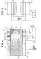
- Fig. 5 is an illustration of a modified embodiment of the invention in which the subsidiary electrodes 30 are coupled edgewise with the outermost electrodes 20 and connected to the same biasing potential Vc.
- the outermost electrodes 20 serve as a part of the subsidiary electrodes 30. This arrangement eliminates the need to observe the close tolerance mentioned above. The sacrificing of two recording electrodes is not substantial for practical purposes.
- the electrodes 20 are formed by initially creating parallel grooves, then follows the vacuum deposition of metal over the entire surface of the support 10. The portions of the metal which lies over raised areas are then removed to produce the grooved electrodes 20. Therefore, the provision of the subsidiary electrodes 30 involves an additional vacuum-deposition step after the metal on the raised areas has been removed.
- the outer end portions of the support 10 are initially machined or etched to create patterns for the subsidiary electrodes 30 together with the grooves for the electrodes 20 and the entire surface is coated by vacuum-deposition of metal and then the raised areas are removed.
- F ig. 6 is an illustration of an example of etching patterns of the recording electrodes 20 and subsidiary electrodes 30.
- Each of the subsidiary electrode patterns comprises an area 30a extending parallel to the end-walls of the support 10 and a plurality of intermediate areas 30b connected from the area 30a to the groove of adjacent outermost electrode 20'.
- the intermediate areas 30b are located adjacent to the front edge of the support 10.
- a layer of metal is deposited on the support 10 and then the portions of the deposited layer on the raised areas are removed, leaving the metal indicated by hatching in the etched areas,
- the metal strip in the area 30a is connected to the voltage source 401 to serve as a current feeder.
- the outermost electrodes 20' are biased to the same potential as in Fig. 5.
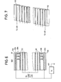
- the subsidiary electrode 30 is further modified as shown in Fig. 7.
- subsidiary electrodes are formed on the front side wall 10a and the end walls 10c, 10d of the support 10.
- Each subsidiary electrode 130 is in contact with the adjacent outermost electrode 20' and extends to the corner of the support and turns to extends along the end wall.
- the outermost electrodes 20' are connected to the voltage source 401 to bias the subsidiary electrodes 130.
- the porous member 4 0 is located so that its outer periphery near the front side and end walls is spaced inwardly therefrom.
- Application of the biasing voltage to the subsidiary electrodes 130 pulls in the otherwise leaking ink via the peripheral areas of the porous member 40 to the upper electrode 50. This embodiment minimizes the areas otherwise occupied by the subsidiary electrodes 30 on the upper surface of the support 10.
- the ink employed in the present invention exhibits a varying electrical resistance and capacitance depending on the amount of its dyestuff in proportion to its solvent. If the amount of ink supply is reduced, the solvent tends to evaporate through the porous member 40 and the dyestuff will increase in proportion to the solvent. As a result, the resistance increases sharply from a certain value as indicated by RL in Fig. 8 and the capacitance decreases sharply from a certain value indicated by C L if the amount of ink contained in the porous member 40 decreases below a limit value a. As a result, the interstices of the porous member 40 are clogged by the excessive dyestuff.
- the ink is excessively supplied to the head 100, the excessive amount of ink will leak through the porous member 40 to the periphery of the support 10.
- a means for controlling the amount of ink supplied to the head 100 at a constant value it is preferable to include a means for controlling the amount of ink supplied to the head 100 at a constant value.
- an embodiment shown in Fig. 9 includes a DC bridge circuit 80 having resistors 81 and 82 connected in the first opposite arms of the bridge and a resistor 83 connected in one of the second opposite arms. The other of the second arms is provided by the electrical resistance between the subsidiary electrode 30 and the upper electrode 50.
- the resistors 81 and 83 are connected in series with the DC voltage source 401 at voltage Vc.
- the values of resistors 81 to 83 are determined so that there is no current in a resistor 85 when the liquid's resistance corresponds to the reference value R L .
- the resistor 85 is coupled to a DC amplifier 86 to supply it with a voltage indicative of the amount of deviation of resistance from R L and the direction of that deviation.
- a flow-rate regulating means 90 is provided in the sponge 70 to respond to the voltage developed in the amplifier 86 by regulating the flow rate of ink supplied to the head 100.
- the regulating means 90 comprises a pair of mesh electrodes 87 and 88 and a porous member 89 between them. When the resistance deviates from R Ll the DC amplifier 86 supplies the electrodes 87 and 88 with a voltage proportional to that deviation to electroosmotically control the movement of the liquid passing through the porous member 89 until the deviation reduces to zero.
- Fig. 10 is an illustration of a circuit 90 for detecting the capacitance value of the ink that permeates the porous member 40.
- the circuit is generally similar to that shown in Fig. 9 with the exception that an AC voltage source 84 is connected in series with the DC voltage source 401 and a capacitor 183 is coupled in parallel with the resistor 83.
- An AC-DC convertor 186 is used instead of the DC amplifier 86.
- the porous member 89 has an average pore size smaller than the average pore size of the porous member 40. This excludes unsoluble dyestuff and foreign particles from the ink and prevents the intrusion of such matters to the porous member 40 to avoid the clogging of the latter.
Landscapes
- Physics & Mathematics (AREA)
- General Physics & Mathematics (AREA)
- Particle Formation And Scattering Control In Inkjet Printers (AREA)
Applications Claiming Priority (4)
| Application Number | Priority Date | Filing Date | Title |
|---|---|---|---|
| JP16021/82 | 1982-02-03 | ||
| JP57016021A JPS58132569A (ja) | 1982-02-03 | 1982-02-03 | インク記録ヘツド |
| JP57097936A JPS58215356A (ja) | 1982-06-07 | 1982-06-07 | インク記録装置 |
| JP97936/82 | 1982-06-07 |
Publications (3)
| Publication Number | Publication Date |
|---|---|
| EP0086597A2 true EP0086597A2 (de) | 1983-08-24 |
| EP0086597A3 EP0086597A3 (en) | 1985-04-03 |
| EP0086597B1 EP0086597B1 (de) | 1988-05-04 |
Family
ID=26352261
Family Applications (1)
| Application Number | Title | Priority Date | Filing Date |
|---|---|---|---|
| EP83300534A Expired EP0086597B1 (de) | 1982-02-03 | 1983-02-02 | Elektroosmotischer Tintendruckkopf |
Country Status (3)
| Country | Link |
|---|---|
| US (1) | US4481520A (de) |
| EP (1) | EP0086597B1 (de) |
| DE (1) | DE3376504D1 (de) |
Families Citing this family (3)
| Publication number | Priority date | Publication date | Assignee | Title |
|---|---|---|---|---|
| JP3161635B2 (ja) * | 1991-10-17 | 2001-04-25 | ソニー株式会社 | インクジェットプリントヘッド及びインクジェットプリンタ |
| IL106803A (en) * | 1993-08-25 | 1998-02-08 | Scitex Corp Ltd | Printable inkjet head |
| US7147955B2 (en) * | 2003-01-31 | 2006-12-12 | Societe Bic | Fuel cartridge for fuel cells |
Family Cites Families (4)
| Publication number | Priority date | Publication date | Assignee | Title |
|---|---|---|---|---|
| CA1109920A (en) * | 1977-07-22 | 1981-09-29 | Nobuo Sonoda | Method and apparatus for nozzleless magnetofluidic recording |
| US4162502A (en) * | 1978-05-05 | 1979-07-24 | Northern Telecom Limited | Printer with electrostatic ink control |
| JPS5738163A (en) * | 1980-08-18 | 1982-03-02 | Matsushita Electric Ind Co Ltd | Image recording method and apparatus therefor |
| US4396925A (en) * | 1980-09-18 | 1983-08-02 | Matsushita Electric Industrial Co., Ltd. | Electroosmotic ink printer |
-
1983
- 1983-01-31 US US06/462,631 patent/US4481520A/en not_active Expired - Fee Related
- 1983-02-02 DE DE8383300534T patent/DE3376504D1/de not_active Expired
- 1983-02-02 EP EP83300534A patent/EP0086597B1/de not_active Expired
Also Published As
| Publication number | Publication date |
|---|---|
| DE3376504D1 (en) | 1988-06-09 |
| US4481520A (en) | 1984-11-06 |
| EP0086597B1 (de) | 1988-05-04 |
| EP0086597A3 (en) | 1985-04-03 |
Similar Documents
| Publication | Publication Date | Title |
|---|---|---|
| EP0048460B1 (de) | Elektroosmotischer Tintendrucker | |
| EP0086675B1 (de) | Elektroosmotischer Tintendrucker | |
| EP0046295B1 (de) | Bildaufzeichnungsvorrichtung | |
| DE3233651C2 (de) | Druckvorrichtung | |
| US4751532A (en) | Thermal electrostatic ink-jet recording head | |
| US6247797B1 (en) | Method and apparatus for ejecting particulate material including secondary electrode disposed transverse to a row of ejection electrodes | |
| DE2615713C3 (de) | Tintenstrahlschreiber | |
| EP0086597B1 (de) | Elektroosmotischer Tintendruckkopf | |
| EP0049843B1 (de) | Tintenaufzeichnungsapparat | |
| DE1671522C3 (de) | Verfahren zur Herstellung eines Ladungsbildes | |
| US4479135A (en) | Ink recording apparatus | |
| JP3135816B2 (ja) | 画像形成装置および画像形成方法 | |
| US4290076A (en) | Compensatory means improving the operation of electrostatic printers | |
| DE3205590A1 (de) | Vorrichtung zum andruecken eines elektrostatischen aufzeichnungsmediums an einen mehrnadelelektrodenkopf | |
| JPH0226586B2 (de) | ||
| DE69700679T2 (de) | Aufzeichnungskopfe für eine elektrostatische Tintenstrahlaufzeichnungsvorrichtung | |
| DE2908446A1 (de) | Druckeinrichtung zur elektrophoretischen aufzeichnung | |
| JPH046550B2 (de) | ||
| EP0760290A2 (de) | Elektrostatischer Tintenstrahldruckkopf | |
| JPH0454586B2 (de) | ||
| DE68914208T2 (de) | Nassaufzeichnungsgerät. | |
| DE3051241C2 (de) | Aufzeichnungskopf zum Ausstoßen von Flüssigkeitströpfchen auf einen Aufzeichnungsträger | |
| JP2845854B2 (ja) | 静電式インクジェット記録ヘッド | |
| DE3824140A1 (de) | Befestigen und elektrisches kontaktieren von piezokeramiken | |
| JP3532018B2 (ja) | 画像形成装置および画像形成方法 |
Legal Events
| Date | Code | Title | Description |
|---|---|---|---|
| PUAI | Public reference made under article 153(3) epc to a published international application that has entered the european phase |
Free format text: ORIGINAL CODE: 0009012 |
|
| AK | Designated contracting states |
Designated state(s): DE FR GB IT NL |
|
| PUAL | Search report despatched |
Free format text: ORIGINAL CODE: 0009013 |
|
| RHK1 | Main classification (correction) |
Ipc: G01D 15/16 |
|
| AK | Designated contracting states |
Designated state(s): DE FR GB IT NL |
|
| 17P | Request for examination filed |
Effective date: 19850328 |
|
| 17Q | First examination report despatched |
Effective date: 19861008 |
|
| GRAA | (expected) grant |
Free format text: ORIGINAL CODE: 0009210 |
|
| AK | Designated contracting states |
Kind code of ref document: B1 Designated state(s): DE FR GB IT NL |
|
| REF | Corresponds to: |
Ref document number: 3376504 Country of ref document: DE Date of ref document: 19880609 |
|
| ET | Fr: translation filed | ||
| ITF | It: translation for a ep patent filed | ||
| PLBE | No opposition filed within time limit |
Free format text: ORIGINAL CODE: 0009261 |
|
| STAA | Information on the status of an ep patent application or granted ep patent |
Free format text: STATUS: NO OPPOSITION FILED WITHIN TIME LIMIT |
|
| 26N | No opposition filed | ||
| ITTA | It: last paid annual fee | ||
| PGFP | Annual fee paid to national office [announced via postgrant information from national office to epo] |
Ref country code: GB Payment date: 19940126 Year of fee payment: 12 |
|
| PGFP | Annual fee paid to national office [announced via postgrant information from national office to epo] |
Ref country code: DE Payment date: 19940209 Year of fee payment: 12 |
|
| PGFP | Annual fee paid to national office [announced via postgrant information from national office to epo] |
Ref country code: FR Payment date: 19940210 Year of fee payment: 12 |
|
| PGFP | Annual fee paid to national office [announced via postgrant information from national office to epo] |
Ref country code: NL Payment date: 19940228 Year of fee payment: 12 |
|
| PG25 | Lapsed in a contracting state [announced via postgrant information from national office to epo] |
Ref country code: GB Effective date: 19950202 |
|
| PG25 | Lapsed in a contracting state [announced via postgrant information from national office to epo] |
Ref country code: NL Effective date: 19950901 |
|
| GBPC | Gb: european patent ceased through non-payment of renewal fee |
Effective date: 19950202 |
|
| PG25 | Lapsed in a contracting state [announced via postgrant information from national office to epo] |
Ref country code: FR Effective date: 19951031 |
|
| NLV4 | Nl: lapsed or anulled due to non-payment of the annual fee |
Effective date: 19950901 |
|
| PG25 | Lapsed in a contracting state [announced via postgrant information from national office to epo] |
Ref country code: DE Effective date: 19951101 |
|
| REG | Reference to a national code |
Ref country code: FR Ref legal event code: ST |