EP0086384B1 - Method of heat-treating a material having a carbon degradable content - Google Patents
Method of heat-treating a material having a carbon degradable content Download PDFInfo
- Publication number
- EP0086384B1 EP0086384B1 EP83100857A EP83100857A EP0086384B1 EP 0086384 B1 EP0086384 B1 EP 0086384B1 EP 83100857 A EP83100857 A EP 83100857A EP 83100857 A EP83100857 A EP 83100857A EP 0086384 B1 EP0086384 B1 EP 0086384B1
- Authority
- EP
- European Patent Office
- Prior art keywords
- accordance
- heating
- intervals
- rates
- maximum
- Prior art date
- Legal status (The legal status is an assumption and is not a legal conclusion. Google has not performed a legal analysis and makes no representation as to the accuracy of the status listed.)
- Expired
Links
- 239000000463 material Substances 0.000 title claims description 46
- OKTJSMMVPCPJKN-UHFFFAOYSA-N Carbon Chemical compound [C] OKTJSMMVPCPJKN-UHFFFAOYSA-N 0.000 title claims description 33
- 229910052799 carbon Inorganic materials 0.000 title claims description 27
- 238000000034 method Methods 0.000 title claims description 25
- 238000010438 heat treatment Methods 0.000 claims description 65
- 229910002804 graphite Inorganic materials 0.000 claims description 6
- 239000010439 graphite Substances 0.000 claims description 6
- 239000011347 resin Substances 0.000 claims description 6
- 229920005989 resin Polymers 0.000 claims description 6
- 230000001419 dependent effect Effects 0.000 claims 1
- 239000000446 fuel Substances 0.000 description 5
- 238000003763 carbonization Methods 0.000 description 2
- 230000000694 effects Effects 0.000 description 2
- 230000015556 catabolic process Effects 0.000 description 1
- 238000006243 chemical reaction Methods 0.000 description 1
- 238000006731 degradation reaction Methods 0.000 description 1
- 238000004519 manufacturing process Methods 0.000 description 1
Images

Classifications
-
- C—CHEMISTRY; METALLURGY
- C04—CEMENTS; CONCRETE; ARTIFICIAL STONE; CERAMICS; REFRACTORIES
- C04B—LIME, MAGNESIA; SLAG; CEMENTS; COMPOSITIONS THEREOF, e.g. MORTARS, CONCRETE OR LIKE BUILDING MATERIALS; ARTIFICIAL STONE; CERAMICS; REFRACTORIES; TREATMENT OF NATURAL STONE
- C04B35/00—Shaped ceramic products characterised by their composition; Ceramics compositions; Processing powders of inorganic compounds preparatory to the manufacturing of ceramic products
- C04B35/515—Shaped ceramic products characterised by their composition; Ceramics compositions; Processing powders of inorganic compounds preparatory to the manufacturing of ceramic products based on non-oxide ceramics
- C04B35/52—Shaped ceramic products characterised by their composition; Ceramics compositions; Processing powders of inorganic compounds preparatory to the manufacturing of ceramic products based on non-oxide ceramics based on carbon, e.g. graphite
- C04B35/528—Shaped ceramic products characterised by their composition; Ceramics compositions; Processing powders of inorganic compounds preparatory to the manufacturing of ceramic products based on non-oxide ceramics based on carbon, e.g. graphite obtained from carbonaceous particles with or without other non-organic components
- C04B35/532—Shaped ceramic products characterised by their composition; Ceramics compositions; Processing powders of inorganic compounds preparatory to the manufacturing of ceramic products based on non-oxide ceramics based on carbon, e.g. graphite obtained from carbonaceous particles with or without other non-organic components containing a carbonisable binder
-
- H—ELECTRICITY
- H01—ELECTRIC ELEMENTS
- H01M—PROCESSES OR MEANS, e.g. BATTERIES, FOR THE DIRECT CONVERSION OF CHEMICAL ENERGY INTO ELECTRICAL ENERGY
- H01M8/00—Fuel cells; Manufacture thereof
- H01M8/02—Details
- H01M8/0202—Collectors; Separators, e.g. bipolar separators; Interconnectors
- H01M8/0204—Non-porous and characterised by the material
- H01M8/0213—Gas-impermeable carbon-containing materials
-
- Y—GENERAL TAGGING OF NEW TECHNOLOGICAL DEVELOPMENTS; GENERAL TAGGING OF CROSS-SECTIONAL TECHNOLOGIES SPANNING OVER SEVERAL SECTIONS OF THE IPC; TECHNICAL SUBJECTS COVERED BY FORMER USPC CROSS-REFERENCE ART COLLECTIONS [XRACs] AND DIGESTS
- Y02—TECHNOLOGIES OR APPLICATIONS FOR MITIGATION OR ADAPTATION AGAINST CLIMATE CHANGE
- Y02E—REDUCTION OF GREENHOUSE GAS [GHG] EMISSIONS, RELATED TO ENERGY GENERATION, TRANSMISSION OR DISTRIBUTION
- Y02E60/00—Enabling technologies; Technologies with a potential or indirect contribution to GHG emissions mitigation
- Y02E60/30—Hydrogen technology
- Y02E60/50—Fuel cells
Definitions
- This invention relates to the treatment of materials and, in particular, to the heat treating of materials having a carbon degradable content in order to convert the carbon degradable content to carbon.
- the plates are subjected to heat which is increased at a uniform rate to the temperature at which the carbon degradable content of the plates is converted to carbon.
- the rate of increase in temperature is maintained quite low (i.e. at about 5°C/hr.). This, in turn, requires that the processing time be quite long (i.e., about 180 hrs.). Long processing times, however, make the process inefficient and undesirable from a production cost standpoint.
- the above and other objectives are realized in a method of heat treating a material having carbon degradable content in order to convert said carbon degradable content to carbon wherein a temperature range is defined and is segmented into several intervals with different heating rates, the method being characterized in that:
- the defined range is a range over the entire extent of which heating of said material can cause blistering, which includes two critical sections with respect to blistering separated by a non or less critical section, each of the two critical sections are segmented into at least two intervals, the maximum heating rate for said material without blistering is determined for each interval, the maximum heating rates of adjacent intervals being different, and wherein the material is heated in each interval at a rate equal to or below the maximum rate for said interval.
- the temperature range for heating is thus divided into intervals and heating during each interval is based on the maximum heating rate supportable within that interval without the occurrence of blistering.
- heating in intervals having high maximum rates can be relatively rapid, thereby enabling an overall reduction in total heating time as compared to the prior practice of using a single rate over the entire range.
- the temperature intervals and heating rates within the intervals are such as to account for temperature gradients present in the heating apparatus.
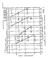
- Figures 1 and 2 indicate graphically for various heating rates and heating intervals the surface condition of materials of different thickness and carbon degradable content.
- the practice of the present invention contemplates heating of the material or materials to be treated in different intervals at rates related to the maximum heating rates determined for these intervals. In order to practice the present invention, it is thus first necessary to segment the defined heating range into intervals and to determine the maximum heating rates for the intervals. Once these parameters are determined, the rates of heating in a particular interval for a material can be determined to thereby practice the invention.
- a heating range will depend upon the particular makeup of the carbon degradable content of the materials to be treated.
- the range should extend to a temperature which is sufficient to ensure substantial conversion of the carbon degradable content to carbon.
- the upper temperature of the range is at a lower temperature for which such carbonization can be realized so as to avoid unnecessary heating and heating time.
- the range is then divided into a plurality of heating intervals.
- the initial selection of the number of intervals can be arbitrary and for the sake of simplicity the intervals can be initially made of equal extent.
- the maximum heating rates can then be determined. In particular, these rates can be established for a material of given thickness and given carbon degradable content ratio for each interval. To accomplish this a sample of the material is heated at a first rate in the first defined interval and then examined to determine whether blistering has occurred. If no blistering has occurred then a new sample of the material is heated at a second rate and examined. This process of heating at different rates is continued until the rate is reached at which blistering first occurs, this rate then being established as the maximum rate for the material of given thickness and given carbon degradable content in the first interval.
- each selected rate should be close to the maximum rate for a particular interval.
- the above procedure should be carried out for each thickness and content combination to assess the maximum heating rates therefor. Heating for a particular material should then be at or below the heating rates associated with the particular thickness and carbon degradable content.
- an equation approximating the particular maximum heating rates for the different combinations can be determined for each interval and this equation used to approximate the maximum rate for other combinations.
- FIGS. 1 and 2 illustrate the results of the above procedure adapted to plates to be used for making fuel cells.
- the particular plates contained various ratios of Varcum O 29-703 resin and Asbury A-99 graphite and were of various thicknesses.
- different indicia indicate points related to different carbon degradable contents and indicia which have been blackened represent points at which blistering occurred and indicia which are clear points at which blistering did not occur.
- the graphical representations demonstrate that certain temperature ranges are much more critical as regards heating rate than other ranges. Thus, the heating rate for the 20 to 200°C range was not critical, while the rate for the 400 to 450°C range was highly critical.
- Table I shows estimated heating programs or cycles determined using the data of Figures 1 and 2 for plates of various thickness.
- heating cycles for plates of .152 cm (.060 inches), .254 cm (.100 inches), .356 cm (.140 inches), .406 cm (.160 inches), .508 cm (.200 inches) and .610 cm (.240 inches) are set forth.
- the cycles in Table I are based upon the use of the maximum heating rates in each temperature interval and result in total heating times which, as can be readily shown, are significantly less than the times which would have resulted from cycles using a uniform heating rate throughout.
- this rate would have had to be set at the lowest maximum rate of all the intervals, if blistering were to be avoided. Hence, the rate would have had to be set at 11°C/hr.
- the cycles of Table I assume a heating apparatus capable of providing the same heating rate to all parts of the material at any given time.
- the heating apparatus employed might well depart from the ideal and exhibit a temperature gradient which would then be imparted to the material.
- the heating rates employed for an interval while always below the maximum rate for that interval, might also have to be below the maximum rate of a subsequent or preceding interval or intervals.
- the rate at any particular time in an interval would have to be equal to or below the lowest of the maximum rates associated with that interval and the other intervals spanned by the temperatures across the material.
- the material will have points which span temperatures between 275°C and 350°C. These temperatures will then encompass the intervals 250°C to 300°C, 300°C to 350°C and 350°C to 400°C and the rate at the beginning of the latter interval will thus have to be below the lowest of the maximum rates for the three intervals. As heating continues, the lowest temperature will be brought out of the 250°C to 300°C interval so at this point the heating rate can be reset at the lowest of the maximum rates for the remaining two intervals. Hence, the actual heating rate during a given interval might change, as the intervals spanned by the temperature across the material change.
Landscapes
- Chemical & Material Sciences (AREA)
- Engineering & Computer Science (AREA)
- Manufacturing & Machinery (AREA)
- Ceramic Engineering (AREA)
- General Chemical & Material Sciences (AREA)
- Structural Engineering (AREA)
- Chemical Kinetics & Catalysis (AREA)
- Electrochemistry (AREA)
- Life Sciences & Earth Sciences (AREA)
- Sustainable Development (AREA)
- Materials Engineering (AREA)
- Sustainable Energy (AREA)
- Organic Chemistry (AREA)
- Resistance Heating (AREA)
- Ceramic Products (AREA)
- Carbon And Carbon Compounds (AREA)
- Fuel Cell (AREA)
- Inert Electrodes (AREA)
Description
- This invention relates to the treatment of materials and, in particular, to the heat treating of materials having a carbon degradable content in order to convert the carbon degradable content to carbon.
- In processes of the above type, it is often desirable that the end effect of the process is carbonization of the carbon degradable content without appreciable disturbance of certain of the other properties of the material. This is especially true in the heat treating of plates to be used to form various gas passages in fuel cells. In particular, in the heat treating of these plates, it is necessary that the surface integrity as well as the negligible through porosity of the plates be maintained. Degradation in surface integrity is evidenced by surface blistering, while increases in through porosity are evidenced by gas leakage, both of which effects could result in a decrease in performance and possible damage to the fuel cell incorporating the plates.
- In one prior practice for heat treating fuel cell plates, the plates are subjected to heat which is increased at a uniform rate to the temperature at which the carbon degradable content of the plates is converted to carbon. To prevent blistering and/or an increase in through porosity beyond predetermined limits, the rate of increase in temperature is maintained quite low (i.e. at about 5°C/hr.). This, in turn, requires that the processing time be quite long (i.e., about 180 hrs.). Long processing times, however, make the process inefficient and undesirable from a production cost standpoint.
- It is therefore an object of the present invention to provide a heat treating practice for materials containing a carbon degradable content which does not suffer from the disadvantages of prior practices.
- It is a further object of the present invention to provide a heat treating practice which is considerably more rapid than prior practices.
- It is also an object of the present invention to provide a heat treating practice for fuel cell plates which can be carried out rapidly without causing surface blistering and/or appreciable increases in through porosity.
- In accordance with the principles of the present invention, the above and other objectives are realized in a method of heat treating a material having carbon degradable content in order to convert said carbon degradable content to carbon wherein a temperature range is defined and is segmented into several intervals with different heating rates, the method being characterized in that:
- the defined range is a range over the entire extent of which heating of said material can cause blistering, which includes two critical sections with respect to blistering separated by a non or less critical section, each of the two critical sections are segmented into at least two intervals, the maximum heating rate for said material without blistering is determined for each interval, the maximum heating rates of adjacent intervals being different, and wherein the material is heated in each interval at a rate equal to or below the maximum rate for said interval.
- With this practice, the temperature range for heating is thus divided into intervals and heating during each interval is based on the maximum heating rate supportable within that interval without the occurrence of blistering. As a result, heating in intervals having high maximum rates can be relatively rapid, thereby enabling an overall reduction in total heating time as compared to the prior practice of using a single rate over the entire range.
- In accordance with a further aspect of the present invention, the temperature intervals and heating rates within the intervals are such as to account for temperature gradients present in the heating apparatus.
- The above and other features and aspects of the present invention will become more apparent upon reading the following detailed description in conjunction with the accompanying drawings in which:
- Figures 1 and 2 indicate graphically for various heating rates and heating intervals the surface condition of materials of different thickness and carbon degradable content.
- As above-indicated, the practice of the present invention contemplates heating of the material or materials to be treated in different intervals at rates related to the maximum heating rates determined for these intervals. In order to practice the present invention, it is thus first necessary to segment the defined heating range into intervals and to determine the maximum heating rates for the intervals. Once these parameters are determined, the rates of heating in a particular interval for a material can be determined to thereby practice the invention.
- The establishment of a heating range will depend upon the particular makeup of the carbon degradable content of the materials to be treated. The range should extend to a temperature which is sufficient to ensure substantial conversion of the carbon degradable content to carbon. Preferably, the upper temperature of the range is at a lower temperature for which such carbonization can be realized so as to avoid unnecessary heating and heating time.
- Once the limits of the heating range are determined, the range is then divided into a plurality of heating intervals. The initial selection of the number of intervals can be arbitrary and for the sake of simplicity the intervals can be initially made of equal extent.
- Having selected the heating intervals, the maximum heating rates can then be determined. In particular, these rates can be established for a material of given thickness and given carbon degradable content ratio for each interval. To accomplish this a sample of the material is heated at a first rate in the first defined interval and then examined to determine whether blistering has occurred. If no blistering has occurred then a new sample of the material is heated at a second rate and examined. This process of heating at different rates is continued until the rate is reached at which blistering first occurs, this rate then being established as the maximum rate for the material of given thickness and given carbon degradable content in the first interval.
- The above procedure is then repeated for the subsequent intervals and maximum heating rates established for these intervals.
- Once the maximum heating rates for each interval are determined, materials to be treated having the given thickness and carbon degradable content can be heated in each interval at the maximum rate or less without blistering occurring. Heating at such rates will also ensure that there will be no appreciable increase in the through porosity of the material as a result of the heating. Preferably, for a fast overall heating time, each selected rate should be close to the maximum rate for a particular interval.
- If the materials to be heated vary in thickness and/or carbon degradable content, then the above procedure should be carried out for each thickness and content combination to assess the maximum heating rates therefor. Heating for a particular material should then be at or below the heating rates associated with the particular thickness and carbon degradable content. In this regard, using the rates established for different combinations, an equation approximating the particular maximum heating rates for the different combinations can be determined for each interval and this equation used to approximate the maximum rate for other combinations.
- The plots of Figures 1 and 2 illustrate the results of the above procedure adapted to plates to be used for making fuel cells. The particular plates contained various ratios of VarcumO 29-703 resin and Asbury A-99 graphite and were of various thicknesses. In the graphs, different indicia indicate points related to different carbon degradable contents and indicia which have been blackened represent points at which blistering occurred and indicia which are clear points at which blistering did not occur.
- As can be observed from these graphical representations, for the materials being tested, the maximum rates for each interval were substantially independent of changes in the ratio of carbon degradable content to total material content. However, the maximum rates did vary for variations in material thickness and equations are presented in the graphs approximating from the measured points the maximum heating rate r in each interval as a function the material thickness t.
- The graphical representations also demonstrate that certain temperature ranges are much more critical as regards heating rate than other ranges. Thus, the heating rate for the 20 to 200°C range was not critical, while the rate for the 400 to 450°C range was highly critical.
- Table I shows estimated heating programs or cycles determined using the data of Figures 1 and 2 for plates of various thickness. In particular, heating cycles for plates of .152 cm (.060 inches), .254 cm (.100 inches), .356 cm (.140 inches), .406 cm (.160 inches), .508 cm (.200 inches) and .610 cm (.240 inches) are set forth.

- The cycles in Table I are based upon the use of the maximum heating rates in each temperature interval and result in total heating times which, as can be readily shown, are significantly less than the times which would have resulted from cycles using a uniform heating rate throughout. Thus, for example, for the cycle associated with .152 cm (.060 inch) thick material, if a uniform rate were used throughout the temperature range, this rate would have had to be set at the lowest maximum rate of all the intervals, if blistering were to be avoided. Hence, the rate would have had to be set at 11°C/hr. Use of such a rate, in turn, would have resulted in a total heating time of approximately 88 hours, as compared to the drastically reduced amount of time, i.e., 12.5 hr., required by the present practice. The cycles for the other thicknesses illustrate a similar relative savings in time, even at the large thickness values (e.g., at the .610 cm (.240 inch) thickness, the total time for uniform heating would have been 4400 hr. as compared with the 612.6 hr. of the present practice).
- It should be noted that in actual practice the rates used for the material thicknesses in the Table I might be made somewhat lower than the maximum rates for safety purposes. This can be accomplished by adding a thickness safety factor s to each actual thickness value t to obtain the value x used in the rate equations.
- It should also be noted that the cycles of Table I assume a heating apparatus capable of providing the same heating rate to all parts of the material at any given time. In practical application, however, the heating apparatus employed might well depart from the ideal and exhibit a temperature gradient which would then be imparted to the material. In such case, the heating rates employed for an interval, while always below the maximum rate for that interval, might also have to be below the maximum rate of a subsequent or preceding interval or intervals. In particular, the rate at any particular time in an interval would have to be equal to or below the lowest of the maximum rates associated with that interval and the other intervals spanned by the temperatures across the material. Thus, for example, if the heating cycle is at the beginning of the temperature interval 350 to 400°C, but the heating apparatus has caused a temperature gradient of 75°C, then the material will have points which span temperatures between 275°C and 350°C. These temperatures will then encompass the intervals 250°C to 300°C, 300°C to 350°C and 350°C to 400°C and the rate at the beginning of the latter interval will thus have to be below the lowest of the maximum rates for the three intervals. As heating continues, the lowest temperature will be brought out of the 250°C to 300°C interval so at this point the heating rate can be reset at the lowest of the maximum rates for the remaining two intervals. Hence, the actual heating rate during a given interval might change, as the intervals spanned by the temperature across the material change.
- In all cases, it is understood that the above-described practices are merely illustrative of the many possible specific embodiments which represent applications of the present invention. Numerous and varied other arrangements can readily be devised in accordance with the principles of the present invention without departing from the scope of the invention.
Claims (14)
Applications Claiming Priority (2)
| Application Number | Priority Date | Filing Date | Title |
|---|---|---|---|
| US344489 | 1982-02-01 | ||
| US06/344,489 US4417872A (en) | 1982-02-01 | 1982-02-01 | Heat treating |
Publications (3)
| Publication Number | Publication Date |
|---|---|
| EP0086384A2 EP0086384A2 (en) | 1983-08-24 |
| EP0086384A3 EP0086384A3 (en) | 1986-02-12 |
| EP0086384B1 true EP0086384B1 (en) | 1989-12-06 |
Family
ID=23350737
Family Applications (1)
| Application Number | Title | Priority Date | Filing Date |
|---|---|---|---|
| EP83100857A Expired EP0086384B1 (en) | 1982-02-01 | 1983-01-31 | Method of heat-treating a material having a carbon degradable content |
Country Status (6)
| Country | Link |
|---|---|
| US (1) | US4417872A (en) |
| EP (1) | EP0086384B1 (en) |
| JP (1) | JPS58140310A (en) |
| BR (1) | BR8300474A (en) |
| CA (1) | CA1195827A (en) |
| DE (1) | DE3380929D1 (en) |
Families Citing this family (1)
| Publication number | Priority date | Publication date | Assignee | Title |
|---|---|---|---|---|
| EP0274702B1 (en) * | 1986-12-18 | 1992-03-18 | Sumitomo Metal Industries, Ltd. | Molding process and device therefor |
Family Cites Families (14)
| Publication number | Priority date | Publication date | Assignee | Title |
|---|---|---|---|---|
| GB860342A (en) | 1956-08-07 | 1961-02-01 | Gen Electric Co Ltd | Improvements in or relating to processes for the production of graphite |
| BE584830A (en) | 1958-11-21 | |||
| GB921236A (en) | 1959-08-28 | 1963-03-20 | Gen Electric Co Ltd | Improvements in or relating to the production of low permeability carbon |
| NL123716C (en) | 1960-01-11 | |||
| GB1024974A (en) | 1962-02-15 | 1966-04-06 | Boulton Aircraft Ltd | Methods of and dies suitable for shaping sheet material |
| US3281509A (en) * | 1963-01-07 | 1966-10-25 | Fialkov Abram Samuilovich | Method for heat treatment of graphite articles |
| FR1388818A (en) | 1963-12-13 | 1965-02-12 | Lorraine Carbone | Macroporous glassy carbon |
| GB1033277A (en) | 1963-12-13 | 1966-06-22 | Tokai Denkyoku Kabushiki Kaish | Improvements in or relating to the manufacture of carbon or graphite bodies |
| FR1573937A (en) * | 1968-02-19 | 1969-07-11 | ||
| GB1228910A (en) | 1968-09-06 | 1971-04-21 | ||
| US3634569A (en) * | 1969-01-08 | 1972-01-11 | United Aircraft Corp | Method of manufacture of dense graphite structures |
| US3914392A (en) * | 1973-03-27 | 1975-10-21 | Us Energy | High temperature insulating carbonaceous material |
| US4030876A (en) * | 1974-06-12 | 1977-06-21 | Unitika Ltd. | Method and apparatus for regenerating activated carbon |
| DE2843676A1 (en) * | 1978-10-06 | 1980-04-24 | Philips Patentverwaltung | METHOD AND DEVICE FOR SOLID PYROLYSIS OF ORGANIC POLYMERS |
-
1982
- 1982-02-01 US US06/344,489 patent/US4417872A/en not_active Expired - Lifetime
-
1983
- 1983-01-13 CA CA000419424A patent/CA1195827A/en not_active Expired
- 1983-01-24 JP JP58010332A patent/JPS58140310A/en active Granted
- 1983-01-31 DE DE8383100857T patent/DE3380929D1/en not_active Expired - Lifetime
- 1983-01-31 BR BR8300474A patent/BR8300474A/en unknown
- 1983-01-31 EP EP83100857A patent/EP0086384B1/en not_active Expired
Also Published As
| Publication number | Publication date |
|---|---|
| BR8300474A (en) | 1983-11-01 |
| JPS58140310A (en) | 1983-08-20 |
| EP0086384A3 (en) | 1986-02-12 |
| DE3380929D1 (en) | 1990-01-11 |
| JPH0159968B2 (en) | 1989-12-20 |
| US4417872A (en) | 1983-11-29 |
| CA1195827A (en) | 1985-10-29 |
| EP0086384A2 (en) | 1983-08-24 |
Similar Documents
| Publication | Publication Date | Title |
|---|---|---|
| US4204769A (en) | Cuvette for flameless atom absorption spectroscopy | |
| US4417872A (en) | Heat treating | |
| US3961888A (en) | Acrylic fiber conversion utilizing a stabilization treatment conducted initially in an essentially inert atmosphere | |
| US6299850B1 (en) | Carbon activation process for increased surface accessibility in electrochemical capacitors | |
| US3321327A (en) | Process for the densification of carbonaceous bodies | |
| US3167447A (en) | Carbon body treatment | |
| Greenstreet et al. | The mechanical behavior of artificial graphites as portrayed by uniaxial tests | |
| Wecker et al. | Study of deformation in polytetrafluoroethylene by x‐ray line broadening | |
| US4521328A (en) | Method of making carbon material | |
| US1670047A (en) | Method of making battery plates | |
| US4728535A (en) | Method of manufacturing thin carbon products | |
| US3475211A (en) | Durable resistive element of glass and a process for preparing the same | |
| US3859422A (en) | Method for reproducibly controlling the crystallinity of synthetic graphite | |
| Tamura et al. | Creep Deformation of Typical Heat Resisting Steels in Long Term Tests | |
| Engle et al. | HIGH-TEMPERATURE IRRADIATION BEHAVIOR OF PRODUCTION-GRADE NUCLEAR GRAPHITES. | |
| Blackman | XLVI. Low Loss Magnesium Manganese Ferrites | |
| Kiessling et al. | Sintering of uranium dioxide | |
| Mochida et al. | Changes of Dynamic Properties of Some Kaolin Minerals by Heat-treatment | |
| Goto et al. | Fatigue Life Assessment of High Temperature Cr--Mo--V Rotors Using X-Ray Diffraction | |
| DE1646611C3 (en) | Process for the subsequent determination of the graphitization temperature of moldings made of carbon or graphite | |
| Hofman et al. | Irradiation behavior of miniature experimental uranium silicide fuel plates | |
| Liu | Deformation and Fracture of Ferrite--Pearlite Steel | |
| Davis | Oxide Growth and Capacitance on Preirradiated Zircaloy‐2 and Zirconium | |
| JPS5613133A (en) | Manufacture of anticorrosion metallic pipe | |
| Simon et al. | Study on anthracene semi-cokes: Eelation between their structural and electronic properties |
Legal Events
| Date | Code | Title | Description |
|---|---|---|---|
| PUAI | Public reference made under article 153(3) epc to a published international application that has entered the european phase |
Free format text: ORIGINAL CODE: 0009012 |
|
| PUAI | Public reference made under article 153(3) epc to a published international application that has entered the european phase |
Free format text: ORIGINAL CODE: 0009012 |
|
| AK | Designated contracting states |
Designated state(s): DE FR GB IT |
|
| PUAL | Search report despatched |
Free format text: ORIGINAL CODE: 0009013 |
|
| AK | Designated contracting states |
Designated state(s): DE FR GB IT |
|
| 17P | Request for examination filed |
Effective date: 19860812 |
|
| 17Q | First examination report despatched |
Effective date: 19870707 |
|
| ITF | It: translation for a ep patent filed | ||
| GRAA | (expected) grant |
Free format text: ORIGINAL CODE: 0009210 |
|
| AK | Designated contracting states |
Kind code of ref document: B1 Designated state(s): DE FR GB IT |
|
| REF | Corresponds to: |
Ref document number: 3380929 Country of ref document: DE Date of ref document: 19900111 |
|
| ET | Fr: translation filed | ||
| ITTA | It: last paid annual fee | ||
| PLBE | No opposition filed within time limit |
Free format text: ORIGINAL CODE: 0009261 |
|
| STAA | Information on the status of an ep patent application or granted ep patent |
Free format text: STATUS: NO OPPOSITION FILED WITHIN TIME LIMIT |
|
| 26N | No opposition filed | ||
| PGFP | Annual fee paid to national office [announced via postgrant information from national office to epo] |
Ref country code: FR Payment date: 19941214 Year of fee payment: 13 |
|
| PGFP | Annual fee paid to national office [announced via postgrant information from national office to epo] |
Ref country code: DE Payment date: 19941227 Year of fee payment: 13 |
|
| PGFP | Annual fee paid to national office [announced via postgrant information from national office to epo] |
Ref country code: GB Payment date: 19941228 Year of fee payment: 13 |
|
| PG25 | Lapsed in a contracting state [announced via postgrant information from national office to epo] |
Ref country code: GB Effective date: 19960131 |
|
| GBPC | Gb: european patent ceased through non-payment of renewal fee |
Effective date: 19960131 |
|
| PG25 | Lapsed in a contracting state [announced via postgrant information from national office to epo] |
Ref country code: FR Effective date: 19960930 |
|
| PG25 | Lapsed in a contracting state [announced via postgrant information from national office to epo] |
Ref country code: DE Effective date: 19961001 |
|
| REG | Reference to a national code |
Ref country code: FR Ref legal event code: ST |