EP0086165B1 - Dispositif pour le maintien, le positionnement et l'entraînement d'un support tubulaire lors de l'enroulement d'une matière en feuille - Google Patents
Dispositif pour le maintien, le positionnement et l'entraînement d'un support tubulaire lors de l'enroulement d'une matière en feuille Download PDFInfo
- Publication number
- EP0086165B1 EP0086165B1 EP83420011A EP83420011A EP0086165B1 EP 0086165 B1 EP0086165 B1 EP 0086165B1 EP 83420011 A EP83420011 A EP 83420011A EP 83420011 A EP83420011 A EP 83420011A EP 0086165 B1 EP0086165 B1 EP 0086165B1
- Authority
- EP
- European Patent Office
- Prior art keywords
- shell
- pivoting
- cradle
- self
- casing
- Prior art date
- Legal status (The legal status is an assumption and is not a legal conclusion. Google has not performed a legal analysis and makes no representation as to the accuracy of the status listed.)
- Expired
Links
- 238000004804 winding Methods 0.000 title description 12
- 239000000463 material Substances 0.000 claims abstract description 13
- 239000000109 continuous material Substances 0.000 claims abstract description 3
- 230000035515 penetration Effects 0.000 claims description 2
- 230000005540 biological transmission Effects 0.000 description 2
- 230000000903 blocking effect Effects 0.000 description 2
- 230000000295 complement effect Effects 0.000 description 2
- 239000004744 fabric Substances 0.000 description 2
- 238000000034 method Methods 0.000 description 2
- 230000006978 adaptation Effects 0.000 description 1
- 238000010586 diagram Methods 0.000 description 1
- 238000006073 displacement reaction Methods 0.000 description 1
- 238000009434 installation Methods 0.000 description 1
- 230000014759 maintenance of location Effects 0.000 description 1
- 238000004519 manufacturing process Methods 0.000 description 1
- 230000002093 peripheral effect Effects 0.000 description 1
- 230000001681 protective effect Effects 0.000 description 1
- 239000004753 textile Substances 0.000 description 1
- 238000011282 treatment Methods 0.000 description 1
Images


Classifications
-
- B—PERFORMING OPERATIONS; TRANSPORTING
- B65—CONVEYING; PACKING; STORING; HANDLING THIN OR FILAMENTARY MATERIAL
- B65H—HANDLING THIN OR FILAMENTARY MATERIAL, e.g. SHEETS, WEBS, CABLES
- B65H18/00—Winding webs
- B65H18/02—Supporting web roll
- B65H18/04—Interior-supporting
-
- B—PERFORMING OPERATIONS; TRANSPORTING
- B65—CONVEYING; PACKING; STORING; HANDLING THIN OR FILAMENTARY MATERIAL
- B65H—HANDLING THIN OR FILAMENTARY MATERIAL, e.g. SHEETS, WEBS, CABLES
- B65H2301/00—Handling processes for sheets or webs
- B65H2301/40—Type of handling process
- B65H2301/41—Winding, unwinding
- B65H2301/413—Supporting web roll
- B65H2301/4136—Mounting arrangements not otherwise provided for
- B65H2301/41366—Mounting arrangements not otherwise provided for arrangements for mounting and supporting and -preferably- driving the (un)winding shaft
- B65H2301/413665—Mounting arrangements not otherwise provided for arrangements for mounting and supporting and -preferably- driving the (un)winding shaft articulated bearing
Definitions
- the present invention relates to a device for holding, positioning and driving a tubular support around which must be wound a continuous material, in sheet form, delivered at constant speed or not, according to the preamble of claim 1.
- a device for holding, positioning and driving a tubular support around which must be wound a continuous material, in sheet form, delivered at constant speed or not, according to the preamble of claim 1.
- Such a device is known from document FR-A-2 443 406.
- the correct winding of the tissues around a tubular support, support which will be designated in the following description by the expression "tube” is generally carried out either by driving the support tube by tangential contact with at least one driving cylinder or , more generally, by placing the tube on which the material is to be wound on a mandrel actuated directly in rotation (axial drive of said support), this mandrel being generally of square section and being held, at each of its ends, by jaws clamp communicating the rotational movement.
- the drive speed of the support mandrel is modified as the diameter of the winding increases, so as to have a constant linear speed and an equally constant tension.
- the device for holding, positioning and driving a tubular support is characterized in that the mounting of the shell inside the housing is achieved by by means of a link also mounted pivoting about a fixed axis, integral with said lower cradle, the tightening and self-locking means associated with said shell being constituted by a link, the ends of which are mounted by means of axes respectively to the housing and the link, the self-locking being ensured by means of rollers mounted eccentrically on the shell.
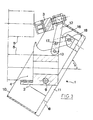
- the jaw according to the invention designated by the general reference (1), and which is capable of being used on any material making it possible to wind a sheet material on a tubular sopport , consists essentially of two elementary parts (2-3) articulated with respect to each other. These two elementary parts (2-3) define between them a cage (4) intended to receive the end of the support tube (5) around which the material is to be wound.
- the part (2) of the jaw will be designated by the expression “lower cradle” while the articulated part (3) will be designated by the expression "clamping shell”.
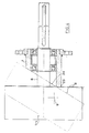
- the lower cradle (2) is mounted at the end of the driving axis (6), shown only in FIG. 4, to ensure the rotation of the jaw.
- This axis (6) is supported by a bearing (7), a particular embodiment of which will be seen in more detail in the following description, and is rotated by any suitable means, for example by a motor (not shown ).
- the shell (3) is pivotally mounted on the lower cradle (2) and comprises means ensuring the tightening and the self-locking of the end of the support tube during winding.
- the retention and articulation of the shell (3) relative to the lower cradle (2) is obtained by means of a housing (8) mounted on the cradle (2) via 'a pivot axis (9).
- This case has an open face (10) and a window (11) on its rear face, allowing it to pivot relative to the fixed lower cradle (2).
- the mounting of the upper shell (3) inside this box (8) is carried out by means of a connecting rod (12) also pivotally mounted around a fixed axis (13) also integral with the lower cradle.
- the cage (4) intended to receive the ends of the tube (5) consists of two circular sectors (or other shape) complementary (14) and (15), one (14 ) formed on the cradle (2), the other (15) on the shell (3).
- the internal faces of these spans (14) and (15) are coated with a layer of protective felt material for example.
- the shell (3) comprises means ensuring the tightening and self-locking of the support tube during the winding of the material.
- clamping and self-locking means are constituted, in this embodiment, by the rod (16) whose ends are mounted, by means of pins (17-18), respectively to the housing (8) and to the link (12).
- the self-locking is ensured by means of rollers (19-20) mounted eccentrically on the shell (3) which, in the closed position, come to bear on the periphery of the support tube (5).
- a clamping force adjustment system constituted for example by a threaded rod (21) mounted on the shell (3), rod which cooperates with a nut (22) integral with the link (12), can be envisaged in order to better define the respective positions between the cradle (2) and said shell (3).
- the jaw according to the invention is mounted on the drive shaft (6) by means of a bearing (7) of particular shape which, automatically , allows to position said jaw so that the lower cradle (2) is necessarily in the low position when it is desired to set up (or remove) the support tube.
- the bearing (7) has an inclined front face whose base (23) serves as a fulcrum for the cradle (2), as well as the housing (8) when it is in the closed position.
- the cutaway (24) of this bearing makes it possible to define the position of the housing (8) in the open position and consequently, to limit the pivoting of the shell (3) to the desired value allowing the positioning and removal of the tube (5).
- the opening and closing can only be carried out with the cradle (2) in the low position.
- Such a bearing shape also makes it possible to ensure very high operating safety of the assembly, taking into account that if, by mistake, the assembly is caused to rotate while the jaw is open, the cutaway will have tendency to automatically cause the shell to close.
- FIGS. 5, 6 and 7 illustrate a variant in accordance with the invention making it possible to use a single device for tubes of variable section, for example of circular, hexagonal, square shape (references 5a, 5b, 5c to Figure 5) and this, at the cost of a simple and quick adaptation to achieve.
- the handling of the assembly is facilitated by providing a peripheral flywheel (31) at the rear of the housing (8).
- the immobilization of the tube and especially in the case of cardboard tubes can be improved by providing on the internal surface of the lower cradle (2) small pins which penetrate inside said tube without however the deteriorate.
- the facing faces (32-33) of the cradle (2) and of the shell (3) may not be smooth and have complementary raised surfaces which interpenetrate (see FIG. 6) and avoid any relative displacement of two elements with respect to each other.
Landscapes
- Replacement Of Web Rolls (AREA)
- Winding Of Webs (AREA)
- Advancing Webs (AREA)
- Unwinding Webs (AREA)
Priority Applications (1)
| Application Number | Priority Date | Filing Date | Title |
|---|---|---|---|
| AT83420011T ATE17110T1 (de) | 1982-02-04 | 1983-01-25 | Vorrichtung zum halten, positionieren und antreiben der wickelwelle beim wickeln von bahnen. |
Applications Claiming Priority (2)
| Application Number | Priority Date | Filing Date | Title |
|---|---|---|---|
| FR8201951A FR2520709A1 (fr) | 1982-02-04 | 1982-02-04 | Dispositif pour le maintien, le positionnement et l'entrainement d'un support tubulaire lors de l'enroulement d'une matiere en feuille |
| FR8201951 | 1982-02-04 |
Publications (2)
| Publication Number | Publication Date |
|---|---|
| EP0086165A1 EP0086165A1 (fr) | 1983-08-17 |
| EP0086165B1 true EP0086165B1 (fr) | 1985-12-27 |
Family
ID=9270742
Family Applications (1)
| Application Number | Title | Priority Date | Filing Date |
|---|---|---|---|
| EP83420011A Expired EP0086165B1 (fr) | 1982-02-04 | 1983-01-25 | Dispositif pour le maintien, le positionnement et l'entraînement d'un support tubulaire lors de l'enroulement d'une matière en feuille |
Country Status (4)
| Country | Link |
|---|---|
| EP (1) | EP0086165B1 (enExample) |
| AT (1) | ATE17110T1 (enExample) |
| DE (1) | DE3361579D1 (enExample) |
| FR (1) | FR2520709A1 (enExample) |
Cited By (1)
| Publication number | Priority date | Publication date | Assignee | Title |
|---|---|---|---|---|
| EP0194356A1 (de) * | 1985-03-14 | 1986-09-17 | Ludwig Boschert GmbH & Co. KG Maschinen- und Apparatebau | Klapplager |
Family Cites Families (2)
| Publication number | Priority date | Publication date | Assignee | Title |
|---|---|---|---|---|
| DE917592C (de) * | 1952-08-15 | 1954-09-06 | Faerberei & Appretur Schutster | Vorrichtung zum Kuppeln von Wickelstaeben |
| DE2852510C2 (de) * | 1978-12-05 | 1983-10-27 | Kunz Maschinen- und Apparatebau GmbH, 7850 Lörrach | Vorrichtung zum Kuppeln von Wickelstäben |
-
1982
- 1982-02-04 FR FR8201951A patent/FR2520709A1/fr active Granted
-
1983
- 1983-01-25 EP EP83420011A patent/EP0086165B1/fr not_active Expired
- 1983-01-25 DE DE8383420011T patent/DE3361579D1/de not_active Expired
- 1983-01-25 AT AT83420011T patent/ATE17110T1/de not_active IP Right Cessation
Cited By (1)
| Publication number | Priority date | Publication date | Assignee | Title |
|---|---|---|---|---|
| EP0194356A1 (de) * | 1985-03-14 | 1986-09-17 | Ludwig Boschert GmbH & Co. KG Maschinen- und Apparatebau | Klapplager |
Also Published As
| Publication number | Publication date |
|---|---|
| EP0086165A1 (fr) | 1983-08-17 |
| DE3361579D1 (en) | 1986-02-06 |
| FR2520709A1 (fr) | 1983-08-05 |
| ATE17110T1 (de) | 1986-01-15 |
| FR2520709B1 (enExample) | 1984-03-16 |
Similar Documents
| Publication | Publication Date | Title |
|---|---|---|
| EP0500405B1 (fr) | Organe de serrage et de préhension | |
| FR2543097A1 (fr) | Frein hydraulique a commande manuelle pour bicyclette et procede de freinage | |
| EP0810944A1 (fr) | Axe de blocage rapide destine a etre utilise sur un cycle | |
| EP0665926B1 (fr) | Frein a tambour a actionnement mecanique | |
| EP1469766B1 (fr) | Dispositif de controle et de regulation de la pression d'une bobine de materiau dans un appareil distributeur a coupe automatique | |
| FR2745524A1 (fr) | Dispositif pour fixer un element de revetement sur un cylindre d'un groupe d'impression | |
| FR2771319A1 (fr) | Dispositif de serrage d'un organe tubulaire notamment au moyen de mors mobiles | |
| EP1054826A1 (fr) | Dispositif de transfert pour corps creux possedant un goulot | |
| EP0385818B1 (fr) | Machine à couper et à plier une bande de papier imprimé | |
| EP0330551B1 (fr) | Pince de préhension automatique d'objet | |
| EP0267112A1 (fr) | Installation de filage de métal | |
| EP0928682B1 (fr) | Machine pour le traitement mécanique du papier comportant des moyens perfectionnés de support d'un rouleau et procédé de remplacements des rouleaux d'une telle machine | |
| EP0086165B1 (fr) | Dispositif pour le maintien, le positionnement et l'entraînement d'un support tubulaire lors de l'enroulement d'une matière en feuille | |
| FR2694233A1 (fr) | Cylindre intermédiaire d'une presse à alimentation par feuilles. | |
| EP0596808B1 (fr) | Tête de bridage | |
| FR3023276A1 (fr) | Dispositif de halage d'un objet de forme tubulaire de grande longueur | |
| FR2745805A1 (fr) | Machine a derouler des bobines en continu comportant au moins un moyen de deroulage de deux bobines jumelees ou coaxiales simultanement | |
| FR2604856A1 (fr) | Presse a grosses balles pour produits de recoltes agricoles | |
| EP0045272B1 (fr) | Dispositif de blocage d'une pièce lors d'une opération d'usinage notamment de perçage | |
| FR2629448A1 (fr) | Appareillage pour decouper une piece en un materiau du type verre ou ceramique le long d'une ligne incisee | |
| FR2700531A1 (fr) | Dispositif de traction sur câble. | |
| EP0394104A1 (fr) | Bloc de serrage à mâchoires auto-serreuses, notamment pour treuil hydraulique linéaire | |
| FR2646627A1 (fr) | Derouleuse de troncs d'arbre avec dispositif antiflexion perfectionne | |
| EP0370914A1 (fr) | Tête de bridage à rattrapage de jeux | |
| FR2649348A1 (fr) | Dispositif pour entrainer en rotation un organe cylindrique |
Legal Events
| Date | Code | Title | Description |
|---|---|---|---|
| PUAI | Public reference made under article 153(3) epc to a published international application that has entered the european phase |
Free format text: ORIGINAL CODE: 0009012 |
|
| AK | Designated contracting states |
Designated state(s): AT BE CH DE GB IT LI NL |
|
| 17P | Request for examination filed |
Effective date: 19840123 |
|
| ITF | It: translation for a ep patent filed | ||
| GRAA | (expected) grant |
Free format text: ORIGINAL CODE: 0009210 |
|
| AK | Designated contracting states |
Designated state(s): AT BE CH DE GB IT LI NL |
|
| PG25 | Lapsed in a contracting state [announced via postgrant information from national office to epo] |
Ref country code: NL Effective date: 19851227 Ref country code: AT Effective date: 19851227 |
|
| REF | Corresponds to: |
Ref document number: 17110 Country of ref document: AT Date of ref document: 19860115 Kind code of ref document: T |
|
| REF | Corresponds to: |
Ref document number: 3361579 Country of ref document: DE Date of ref document: 19860206 |
|
| NLV1 | Nl: lapsed or annulled due to failure to fulfill the requirements of art. 29p and 29m of the patents act | ||
| PLBE | No opposition filed within time limit |
Free format text: ORIGINAL CODE: 0009261 |
|
| STAA | Information on the status of an ep patent application or granted ep patent |
Free format text: STATUS: NO OPPOSITION FILED WITHIN TIME LIMIT |
|
| 26N | No opposition filed | ||
| PG25 | Lapsed in a contracting state [announced via postgrant information from national office to epo] |
Ref country code: LI Effective date: 19870131 Ref country code: CH Effective date: 19870131 |
|
| BERE | Be: lapsed |
Owner name: CHOGNARD JEAN-LOUIS Effective date: 19870131 |
|
| GBPC | Gb: european patent ceased through non-payment of renewal fee | ||
| REG | Reference to a national code |
Ref country code: CH Ref legal event code: PL |
|
| PG25 | Lapsed in a contracting state [announced via postgrant information from national office to epo] |
Ref country code: DE Effective date: 19871001 |
|
| PG25 | Lapsed in a contracting state [announced via postgrant information from national office to epo] |
Ref country code: GB Effective date: 19881122 |
|
| PG25 | Lapsed in a contracting state [announced via postgrant information from national office to epo] |
Ref country code: BE Effective date: 19890131 |