EP0085486B1 - Antennenanordnung - Google Patents
Antennenanordnung Download PDFInfo
- Publication number
- EP0085486B1 EP0085486B1 EP83300139A EP83300139A EP0085486B1 EP 0085486 B1 EP0085486 B1 EP 0085486B1 EP 83300139 A EP83300139 A EP 83300139A EP 83300139 A EP83300139 A EP 83300139A EP 0085486 B1 EP0085486 B1 EP 0085486B1
- Authority
- EP
- European Patent Office
- Prior art keywords
- antenna
- transmission line
- triplate
- plane
- aperture
- Prior art date
- Legal status (The legal status is an assumption and is not a legal conclusion. Google has not performed a legal analysis and makes no representation as to the accuracy of the status listed.)
- Expired
Links
Images


Classifications
-
- H—ELECTRICITY
- H01—ELECTRIC ELEMENTS
- H01Q—ANTENNAS, i.e. RADIO AERIALS
- H01Q13/00—Waveguide horns or mouths; Slot antennas; Leaky-waveguide antennas; Equivalent structures causing radiation along the transmission path of a guided wave
- H01Q13/10—Resonant slot antennas
-
- H—ELECTRICITY
- H01—ELECTRIC ELEMENTS
- H01Q—ANTENNAS, i.e. RADIO AERIALS
- H01Q21/00—Antenna arrays or systems
- H01Q21/06—Arrays of individually energised antenna units similarly polarised and spaced apart
- H01Q21/061—Two dimensional planar arrays
- H01Q21/062—Two dimensional planar arrays using dipole aerials
-
- H—ELECTRICITY
- H01—ELECTRIC ELEMENTS
- H01Q—ANTENNAS, i.e. RADIO AERIALS
- H01Q9/00—Electrically-short antennas having dimensions not more than twice the operating wavelength and consisting of conductive active radiating elements
- H01Q9/04—Resonant antennas
- H01Q9/16—Resonant antennas with feed intermediate between the extremities of the antenna, e.g. centre-fed dipole
- H01Q9/26—Resonant antennas with feed intermediate between the extremities of the antenna, e.g. centre-fed dipole with folded element or elements, the folded parts being spaced apart a small fraction of operating wavelength
Definitions
- This invention relates to antennas which are suitable for transmitting and receiving plane polarised electro-magnetic radiation at a very high frequency, typically in excess of 1 GHz.
- a dipole is particularly suitable for this purpose, but it has proved difficult to satisfactorily produce an antenna arrangement containing an array of dipoles in which the impedance of the dipole is acceptably constant over a reasonably broad bandwidth.
- a triplate transmission line sometimes termed strip-line
- the dipoles lie in the same plane as the triplate, but the electrical performance can be rather unsatisfactory.
- dipole antenna is disclosed in DE-A-2621452, in which a dipole consisting of two co-planar portions which are spaced apart by an elongate aperture is connected to a strip-line feeder.
- the present invention seeks to provide an improved dipole antenna arrangement which utilises a triplate feeder.
- an antenna includes a triplate transmission line having an elongate central conductor sandwiched between two ground planes both of which terminate in two narrow extensions thereof which are separated by two respective longitudinal slots aligned with each other, and the elongate central conductor, the ends of that pair of extensions lying to one side of the longitudinal slots, both being electrically connected to said central conductor, and the ends of the other pair of extensions being connected together; a dipole radiator comprising two co-planar plate portions spaced apart by an elongate aperture, the plate portions being electrically connected together at each end of the elongate aperture, and a mid-point on each side of the aperture being electrically connected to respective ones of said pairs of said extensions; and a planar reflector mounted at the base of said extensions so as to be substantially parallel to said dipole radiator and perpendicular to the triplate transmission line.
- the elongate aperture in the dipole radiator is disposed perpendicularly to the plane of the triplate transmission line, whereas for radiation which is plane polarised perpendicular to the plane of the transmission line, the elongate aperture is aligned with the plane of the transmission line itself.
- the input impedance of the dipole radiator can be made substantially equal to the characteristic impedance of the triplate transmission line over a reasonably wide bandwidth.
- Correct impedance matching is important to prevent undesirable energy loss, either when the antenna is operative to radiate energy, or when it is operative to receive energy.
- the extensions of the ground plane can be shaped so as to provide an impedance transformation between that of the body of the triplate transmission line, and that of the dipole reflector.
- the two co-planar plate portions of the dipole radiator form part of a single continuous conductive sheet having the elongate aperture formed within it.
- the elongate aperture is preferably provided at each end with portions which are considerably wider than the width of the aperture at the mid-point.
- the elongate aperture takes the form of an H.
- the triplate consists of two ground planes which sandwich between them a central conductor in conventional manner - a construction of this kind is sometimes called "stripline".
- the central conductor is spaced apart from each of the two ground planes by a layer of rigid dielectric material, although alternatively an air gap can be provided.
- the invention is particularly applicable to antenna arrangements which contain a large number of similar dipoles mounted side by side, and in such a case preferably a plurality of dipole radiators are connected to a common triplate structure. That is to say, the two ground planes are common, although each triplate transmission line will possess its own separate central conductor.
- a common elongate reflector is provided for all the dipoles which are mounted on the common triplate structure.
- the antenna comprises a triplate structure 1 which itself can be of conventional form, that is to say, it consists of two ground planes 2, 3 which sandwich between them an elongate conductor 4, which is relatively narrow and very thin.
- the two ground planes 2, 3 are spaced apart from the central conductor by sheets 5, 6 of rigid dielectric material such as a suitable polyurethane foam.
- the conductor 4 can be formed as a thin foil printed onto a thin flexible insulating substrate, but the substrate is not separately shown, as its thickness is negligible as compared with that of the sheets 5 and 6.
- the central conductor 4, together with the two ground planes 2 and 3 comprises a transmission line which in operation is connected to an unbalanced transmission line (not shown but which takes the form of a co-axial cable) by a connector 7.
- the transmission line serves to connect the connector 7 to a half-wavelength dipole radiator 8.
- the dipole radiator 8 comprises a flat sheet of metal having an elongate aperture 10 formed centrally in it to define two flat co-planar portions 91 and 92 on either side of it. Each end of the aperture is locally widened so that overall the aperture is in the form of an H.
- the dimensions of the plate radiator 8 and the aperture 10 determine the effective impedance of the dipole radiator, and this determines the effective bandwidth of the antenna.
- the dipole radiator is nominally a half-wavelength radiator, it is capable of operating over a band of frequencies, the bandwidth of which depends on the size and shape of the plate.
- the dipole radiator 8 is coupled to the triplate structure 1 by four extensions, 11, 12, 13, 14 of the ground planes 2 and 3.
- the two extensions 11 and 12 form part of the upper ground plane 2 and are separated from each other by a longitudinal slot 15 which is approximately a quarter wavelength long.
- the extensions 13 and 14 of the lower ground plane 3 are provided with a similar slot 16 which is aligned with the slot 15 and with the central conductor 4.
- the pair of extensions 11 and 13 which lie on one side of the slots, 15 and 16 are each connected to the central conductor 4 by means of electrically conductive pins 17 and 18 whereas the other two extensions 12 and 14 are directly connected together by a link 19.
- the end of the central conductor 4 is provided with a suitable cut-out 20 as to clear the link 19.
- a reflector plate 25 is mounted on the triplate structure at the base of the extensions 11, 12, 13, 14 so as to be perpendicular to the plane of the triplate structure.
- a high frequency signal typically in excess of 1 GHz is coupled via a co-axial cable to the connector 7 and is transmitted along the transmission line to the dipole radiator 8. It is radiated as a plane polarised wave having a plane of polarisation which is determined by the orientation of the aperture 10 with respect to the plane of the triplate structure 1.
- the antenna is, of course, a reciprocal device and it is operative in a similar manner to receive a high frequency signal and the appropriate plane polarised components of the received signal are coupled by the antenna to the conductor 7 for utilisation as required.
- the cross bar of the H is aligned with the plane of the triplate structure 1 and because of this the antenna handles radiation which is plane polarised perpendicular to the plane of the triplate structure.
- the dipole 8 is mounted on the triplate structure by two thin electrically conductive links 21 and 22 the link 22 extending from the tip of the extension 11 to the mid-point 23 of the upper edge of the aperture 10, and the other link extending from the tip of the diagonally opposite extension 14 to the mid-point 24 of the lower edge of the aperture 10. These mid-points are approximate only, and need not lie exactly one above the other.
- the bandwidth of the dipole radiator depends on the size and shape of the plate.
- the bandwidth is increased as the width a (see Figure 3) is increased, but as the width a increases, the length b must be correspondingly reduced to maintain a given centre frequency of operation.
- the width a is between 1/4X and 3/8 ⁇ , and the length b is between 1/2 ⁇ and 1/ 3 ⁇ .
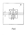
- the cross bar of the H is perpendicular to the plane of the triplate structure 1.
- the antenna handles radiation which is plane polarised in the plane of the triplate structure itself.
- the dipole 8 is mounted on the triplate structure by means of a stub 30 extending from the link 19, and by the end 31 of the conductor 4, which respectively are connected to the mid-point 32 of one edge of the aperture 10, and to the mid-point 33 of the other edge of the aperture 10. These mid-points are approximate only, and need not lie exactly opposite each other.
- the invention is particularly applicable to large antenna arrangements containing a great many individual dipole radiators.
- An antenna arrangement of this kind is illustrated diagrammatically in Figure 7.
- a common triplate structure 41 is similar in construction to the structure 1 described with reference to the preceding Figures.
- a number of similar dipole radiators 48 are coupled to respective connectors 47 via central conductors 44 positioned between the two ground plates of the triplate structure 41.
- a common reflector plate 50 is provided for all of the dipole radiators 48.
- the difference dipole radiators By controlling the relative phases of the high frequency signal transmitted by the difference dipole radiators they can be arranged to combine constructively so as to produce a narrow steerable beam of electro-magnetic energy. In order to produce a very narrow beam having low side lobes, it is desirable to provide a very large number of individual dipole radiators.
- the form of construction illustrated enables this requirement to be met with precision and at relatively low cost. Although only a two dimensional array of dipole radiators is shown, a three dimensional array can easily be made by stacking a large number of individual triplate structures one above the other.
- the reflector 25 is shown as a single plate mounted on the edge of the triplate structure. In some instances it may be more convenient to make it in two pieces 251 and 252, as shown in Figure 5, the dipole radiator 8 itself is unchanged and contains aperture 10 as previously.
Claims (7)
Priority Applications (1)
| Application Number | Priority Date | Filing Date | Title |
|---|---|---|---|
| AT83300139T ATE26195T1 (de) | 1982-01-15 | 1983-01-12 | Antennenanordnung. |
Applications Claiming Priority (6)
| Application Number | Priority Date | Filing Date | Title |
|---|---|---|---|
| GB8201084 | 1982-01-15 | ||
| GB8201084 | 1982-01-15 | ||
| GB8216515 | 1982-06-07 | ||
| GB8216515 | 1982-06-07 | ||
| GB08232564A GB2113476B (en) | 1982-01-15 | 1982-11-15 | Antenna arrangement |
| GB8232564 | 1982-11-15 |
Publications (2)
| Publication Number | Publication Date |
|---|---|
| EP0085486A1 EP0085486A1 (de) | 1983-08-10 |
| EP0085486B1 true EP0085486B1 (de) | 1987-03-25 |
Family
ID=27261424
Family Applications (1)
| Application Number | Title | Priority Date | Filing Date |
|---|---|---|---|
| EP83300139A Expired EP0085486B1 (de) | 1982-01-15 | 1983-01-12 | Antennenanordnung |
Country Status (4)
| Country | Link |
|---|---|
| US (1) | US4528568A (de) |
| EP (1) | EP0085486B1 (de) |
| DE (1) | DE3370567D1 (de) |
| GB (1) | GB2113476B (de) |
Families Citing this family (12)
| Publication number | Priority date | Publication date | Assignee | Title |
|---|---|---|---|---|
| FR2583226B1 (fr) * | 1985-06-10 | 1988-03-25 | France Etat | Antenne omnidirectionnelle cylindrique |
| GB8612908D0 (en) * | 1986-05-28 | 1986-07-02 | Gen Electric Co Plc | Antenna |
| GB2207286A (en) * | 1987-07-22 | 1989-01-25 | Gen Electric Co Plc | Dipole antenna |
| GB2212665B (en) * | 1987-11-23 | 1991-09-04 | Gen Electric Co Plc | A slot antenna |
| FR2634325B1 (fr) * | 1988-07-13 | 1990-09-14 | Thomson Csf | Antenne comportant des circuits de distribution d'energie micro-onde du type triplaque |
| FR2655202B1 (fr) * | 1989-11-24 | 1992-02-07 | Thomson Csf | Antenne a polarisation circulaire, notamment pour reseau d'antennes. |
| FI120522B (fi) * | 2006-03-02 | 2009-11-13 | Filtronic Comtek Oy | Uudenlainen antennirakenne ja menetelmä sen valmistamiseksi |
| US8816910B2 (en) * | 2012-06-20 | 2014-08-26 | Mediatek Inc. | Flexible transmission device and communication device using the same |
| JP6003811B2 (ja) * | 2013-06-05 | 2016-10-05 | 日立金属株式会社 | アンテナ装置 |
| CN103730728B (zh) * | 2013-12-31 | 2016-09-07 | 上海贝尔股份有限公司 | 多频天线 |
| CA3057782C (en) * | 2018-10-23 | 2022-03-22 | Neptune Technology Group Inc. | Compact folded dipole antenna with multiple frequency bands |
| US10992045B2 (en) * | 2018-10-23 | 2021-04-27 | Neptune Technology Group Inc. | Multi-band planar antenna |
Family Cites Families (9)
| Publication number | Priority date | Publication date | Assignee | Title |
|---|---|---|---|---|
| NL77658C (de) * | 1946-03-15 | |||
| US2555443A (en) * | 1948-06-08 | 1951-06-05 | Sylvania Electric Prod | Radio apparatus employing slot antenna |
| US2860339A (en) * | 1953-02-11 | 1958-11-11 | Itt | Ultra-high frequency antenna unit |
| GB756381A (en) * | 1953-12-09 | 1956-09-05 | Emi Ltd | Improvements in or relating to slot aerials |
| FR2311422A1 (fr) * | 1975-05-15 | 1976-12-10 | France Etat | Doublet replie en plaques |
| JPS53103356A (en) * | 1977-02-21 | 1978-09-08 | Mitsubishi Electric Corp | Antenna device |
| FR2442520A1 (fr) * | 1978-11-27 | 1980-06-20 | Havot Henri | Antenne en plaques a double boucles circulaires |
| US4319249A (en) * | 1980-01-30 | 1982-03-09 | Westinghouse Electric Corp. | Method and antenna for improved sidelobe performance in dipole arrays |
| FR2487588A1 (fr) * | 1980-07-23 | 1982-01-29 | France Etat | Doublets replies en plaques pour tres haute frequence et reseaux de tels doublets |
-
1982
- 1982-11-15 GB GB08232564A patent/GB2113476B/en not_active Expired
-
1983
- 1983-01-12 DE DE8383300139T patent/DE3370567D1/de not_active Expired
- 1983-01-12 US US06/457,453 patent/US4528568A/en not_active Expired - Fee Related
- 1983-01-12 EP EP83300139A patent/EP0085486B1/de not_active Expired
Also Published As
| Publication number | Publication date |
|---|---|
| DE3370567D1 (en) | 1987-04-30 |
| GB2113476B (en) | 1985-07-03 |
| US4528568A (en) | 1985-07-09 |
| EP0085486A1 (de) | 1983-08-10 |
| GB2113476A (en) | 1983-08-03 |
Similar Documents
| Publication | Publication Date | Title |
|---|---|---|
| US5070340A (en) | Broadband microstrip-fed antenna | |
| US5675345A (en) | Compact antenna with folded substrate | |
| US4287518A (en) | Cavity-backed, micro-strip dipole antenna array | |
| EP0456680B1 (de) | Gruppenantennen | |
| US4130822A (en) | Slot antenna | |
| US5581266A (en) | Printed-circuit crossed-slot antenna | |
| US4590478A (en) | Multiple ridge antenna | |
| US3681769A (en) | Dual polarized printed circuit dipole antenna array | |
| US5045862A (en) | Dual polarization microstrip array antenna | |
| US3938161A (en) | Microstrip antenna structure | |
| US4623894A (en) | Interleaved waveguide and dipole dual band array antenna | |
| KR100207600B1 (ko) | 공진기 부착형 마이크로스트립 다이폴 안테나 어레이 | |
| EP0685900B1 (de) | Antenne | |
| US6281843B1 (en) | Planar broadband dipole antenna for linearly polarized waves | |
| US4125839A (en) | Dual diagonally fed electric microstrip dipole antennas | |
| EP1790033B1 (de) | Reflexionsantenne | |
| US6133878A (en) | Microstrip array antenna | |
| EP0360861B1 (de) | Zirkular polarisierte streifenleitungsantennengruppe | |
| US3987455A (en) | Microstrip antenna | |
| EP0104536A2 (de) | In Streifenleitungstechnik ausgeführte Reflektorgruppenantenne für Satellitenverbindungen und zur Vergrösserung oder Verminderung der Zurückstrahlbarkeit von Radarwellen | |
| US4087822A (en) | Radio frequency antenna having microstrip feed network and flared radiating aperture | |
| JPH0671171B2 (ja) | 広帯域アンテナ | |
| JP2846081B2 (ja) | トリプレート型平面アンテナ | |
| US6087988A (en) | In-line CP patch radiator | |
| US4656482A (en) | Wideband wing-conformal phased-array antenna having dielectric-loaded log-periodic electrically-small, folded monopole elements |
Legal Events
| Date | Code | Title | Description |
|---|---|---|---|
| PUAI | Public reference made under article 153(3) epc to a published international application that has entered the european phase |
Free format text: ORIGINAL CODE: 0009012 |
|
| AK | Designated contracting states |
Designated state(s): AT BE CH DE FR IT LI LU NL SE |
|
| 17P | Request for examination filed |
Effective date: 19830908 |
|
| GRAA | (expected) grant |
Free format text: ORIGINAL CODE: 0009210 |
|
| AK | Designated contracting states |
Kind code of ref document: B1 Designated state(s): AT BE CH DE FR IT LI LU NL SE |
|
| PG25 | Lapsed in a contracting state [announced via postgrant information from national office to epo] |
Ref country code: AT Effective date: 19870325 Ref country code: BE Effective date: 19870325 Ref country code: CH Effective date: 19870325 Ref country code: LI Effective date: 19870325 |
|
| REF | Corresponds to: |
Ref document number: 26195 Country of ref document: AT Date of ref document: 19870415 Kind code of ref document: T |
|
| ITF | It: translation for a ep patent filed |
Owner name: JACOBACCI & PERANI S.P.A. |
|
| REF | Corresponds to: |
Ref document number: 3370567 Country of ref document: DE Date of ref document: 19870430 |
|
| ET | Fr: translation filed | ||
| REG | Reference to a national code |
Ref country code: CH Ref legal event code: PL |
|
| PLBE | No opposition filed within time limit |
Free format text: ORIGINAL CODE: 0009261 |
|
| STAA | Information on the status of an ep patent application or granted ep patent |
Free format text: STATUS: NO OPPOSITION FILED WITHIN TIME LIMIT |
|
| PG25 | Lapsed in a contracting state [announced via postgrant information from national office to epo] |
Ref country code: LU Free format text: LAPSE BECAUSE OF NON-PAYMENT OF DUE FEES Effective date: 19880131 |
|
| 26N | No opposition filed | ||
| PGFP | Annual fee paid to national office [announced via postgrant information from national office to epo] |
Ref country code: NL Payment date: 19890131 Year of fee payment: 10 |
|
| PGFP | Annual fee paid to national office [announced via postgrant information from national office to epo] |
Ref country code: SE Payment date: 19891222 Year of fee payment: 8 |
|
| PGFP | Annual fee paid to national office [announced via postgrant information from national office to epo] |
Ref country code: FR Payment date: 19891228 Year of fee payment: 8 |
|
| ITTA | It: last paid annual fee | ||
| PGFP | Annual fee paid to national office [announced via postgrant information from national office to epo] |
Ref country code: DE Payment date: 19900223 Year of fee payment: 8 |
|
| PG25 | Lapsed in a contracting state [announced via postgrant information from national office to epo] |
Ref country code: SE Effective date: 19910113 |
|
| PG25 | Lapsed in a contracting state [announced via postgrant information from national office to epo] |
Ref country code: NL Effective date: 19910801 |
|
| NLV4 | Nl: lapsed or anulled due to non-payment of the annual fee | ||
| PG25 | Lapsed in a contracting state [announced via postgrant information from national office to epo] |
Ref country code: FR Effective date: 19910930 |
|
| PG25 | Lapsed in a contracting state [announced via postgrant information from national office to epo] |
Ref country code: DE Effective date: 19911001 |
|
| REG | Reference to a national code |
Ref country code: FR Ref legal event code: ST |
|
| EUG | Se: european patent has lapsed |
Ref document number: 83300139.9 Effective date: 19910910 |