EP0085147B1 - Straight flat shaft for a joint endoprosthesis - Google Patents
Straight flat shaft for a joint endoprosthesis Download PDFInfo
- Publication number
- EP0085147B1 EP0085147B1 EP82110500A EP82110500A EP0085147B1 EP 0085147 B1 EP0085147 B1 EP 0085147B1 EP 82110500 A EP82110500 A EP 82110500A EP 82110500 A EP82110500 A EP 82110500A EP 0085147 B1 EP0085147 B1 EP 0085147B1
- Authority
- EP
- European Patent Office
- Prior art keywords
- stem
- blade
- end piece
- narrow side
- shaft
- Prior art date
- Legal status (The legal status is an assumption and is not a legal conclusion. Google has not performed a legal analysis and makes no representation as to the accuracy of the status listed.)
- Expired
Links
- 241000309551 Arthraxon hispidus Species 0.000 claims abstract description 13
- 210000004394 hip joint Anatomy 0.000 claims description 5
- 230000007704 transition Effects 0.000 claims description 3
- 210000000988 bone and bone Anatomy 0.000 description 12
- 238000004873 anchoring Methods 0.000 description 5
- 239000007943 implant Substances 0.000 description 5
- RTAQQCXQSZGOHL-UHFFFAOYSA-N Titanium Chemical compound [Ti] RTAQQCXQSZGOHL-UHFFFAOYSA-N 0.000 description 3
- 239000000463 material Substances 0.000 description 3
- 239000010936 titanium Substances 0.000 description 3
- 229910052719 titanium Inorganic materials 0.000 description 3
- 238000003466 welding Methods 0.000 description 3
- 229910045601 alloy Inorganic materials 0.000 description 2
- 239000000956 alloy Substances 0.000 description 2
- 239000004568 cement Substances 0.000 description 2
- 238000010276 construction Methods 0.000 description 2
- 229910052751 metal Inorganic materials 0.000 description 2
- 239000002184 metal Substances 0.000 description 2
- 150000002739 metals Chemical class 0.000 description 2
- ATJFFYVFTNAWJD-UHFFFAOYSA-N Tin Chemical compound [Sn] ATJFFYVFTNAWJD-UHFFFAOYSA-N 0.000 description 1
- 230000005540 biological transmission Effects 0.000 description 1
- 239000002639 bone cement Substances 0.000 description 1
- 229910010293 ceramic material Inorganic materials 0.000 description 1
- 238000000576 coating method Methods 0.000 description 1
- 239000002131 composite material Substances 0.000 description 1
- 238000012937 correction Methods 0.000 description 1
- 230000001054 cortical effect Effects 0.000 description 1
- 210000005257 cortical tissue Anatomy 0.000 description 1
- 238000005516 engineering process Methods 0.000 description 1
- 238000000605 extraction Methods 0.000 description 1
- 210000002436 femur neck Anatomy 0.000 description 1
- 239000000945 filler Substances 0.000 description 1
- 210000001624 hip Anatomy 0.000 description 1
- 238000002513 implantation Methods 0.000 description 1
- 229910001092 metal group alloy Inorganic materials 0.000 description 1
- 239000000126 substance Substances 0.000 description 1
- 210000001519 tissue Anatomy 0.000 description 1
- 210000000689 upper leg Anatomy 0.000 description 1
Images
Classifications
-
- A—HUMAN NECESSITIES
- A61—MEDICAL OR VETERINARY SCIENCE; HYGIENE
- A61F—FILTERS IMPLANTABLE INTO BLOOD VESSELS; PROSTHESES; DEVICES PROVIDING PATENCY TO, OR PREVENTING COLLAPSING OF, TUBULAR STRUCTURES OF THE BODY, e.g. STENTS; ORTHOPAEDIC, NURSING OR CONTRACEPTIVE DEVICES; FOMENTATION; TREATMENT OR PROTECTION OF EYES OR EARS; BANDAGES, DRESSINGS OR ABSORBENT PADS; FIRST-AID KITS
- A61F2/00—Filters implantable into blood vessels; Prostheses, i.e. artificial substitutes or replacements for parts of the body; Appliances for connecting them with the body; Devices providing patency to, or preventing collapsing of, tubular structures of the body, e.g. stents
- A61F2/02—Prostheses implantable into the body
- A61F2/30—Joints
- A61F2/30721—Accessories
- A61F2/30734—Modular inserts, sleeves or augments, e.g. placed on proximal part of stem for fixation purposes or wedges for bridging a bone defect
-
- A—HUMAN NECESSITIES
- A61—MEDICAL OR VETERINARY SCIENCE; HYGIENE
- A61F—FILTERS IMPLANTABLE INTO BLOOD VESSELS; PROSTHESES; DEVICES PROVIDING PATENCY TO, OR PREVENTING COLLAPSING OF, TUBULAR STRUCTURES OF THE BODY, e.g. STENTS; ORTHOPAEDIC, NURSING OR CONTRACEPTIVE DEVICES; FOMENTATION; TREATMENT OR PROTECTION OF EYES OR EARS; BANDAGES, DRESSINGS OR ABSORBENT PADS; FIRST-AID KITS
- A61F2/00—Filters implantable into blood vessels; Prostheses, i.e. artificial substitutes or replacements for parts of the body; Appliances for connecting them with the body; Devices providing patency to, or preventing collapsing of, tubular structures of the body, e.g. stents
- A61F2/02—Prostheses implantable into the body
- A61F2/30—Joints
- A61F2/32—Joints for the hip
- A61F2/36—Femoral heads ; Femoral endoprostheses
- A61F2/3662—Femoral shafts
-
- A—HUMAN NECESSITIES
- A61—MEDICAL OR VETERINARY SCIENCE; HYGIENE
- A61F—FILTERS IMPLANTABLE INTO BLOOD VESSELS; PROSTHESES; DEVICES PROVIDING PATENCY TO, OR PREVENTING COLLAPSING OF, TUBULAR STRUCTURES OF THE BODY, e.g. STENTS; ORTHOPAEDIC, NURSING OR CONTRACEPTIVE DEVICES; FOMENTATION; TREATMENT OR PROTECTION OF EYES OR EARS; BANDAGES, DRESSINGS OR ABSORBENT PADS; FIRST-AID KITS
- A61F2/00—Filters implantable into blood vessels; Prostheses, i.e. artificial substitutes or replacements for parts of the body; Appliances for connecting them with the body; Devices providing patency to, or preventing collapsing of, tubular structures of the body, e.g. stents
- A61F2/02—Prostheses implantable into the body
- A61F2/30—Joints
- A61F2002/30001—Additional features of subject-matter classified in A61F2/28, A61F2/30 and subgroups thereof
- A61F2002/30316—The prosthesis having different structural features at different locations within the same prosthesis; Connections between prosthetic parts; Special structural features of bone or joint prostheses not otherwise provided for
- A61F2002/30329—Connections or couplings between prosthetic parts, e.g. between modular parts; Connecting elements
- A61F2002/30383—Connections or couplings between prosthetic parts, e.g. between modular parts; Connecting elements made by laterally inserting a protrusion, e.g. a rib into a complementarily-shaped groove
-
- A—HUMAN NECESSITIES
- A61—MEDICAL OR VETERINARY SCIENCE; HYGIENE
- A61F—FILTERS IMPLANTABLE INTO BLOOD VESSELS; PROSTHESES; DEVICES PROVIDING PATENCY TO, OR PREVENTING COLLAPSING OF, TUBULAR STRUCTURES OF THE BODY, e.g. STENTS; ORTHOPAEDIC, NURSING OR CONTRACEPTIVE DEVICES; FOMENTATION; TREATMENT OR PROTECTION OF EYES OR EARS; BANDAGES, DRESSINGS OR ABSORBENT PADS; FIRST-AID KITS
- A61F2220/00—Fixations or connections for prostheses classified in groups A61F2/00 - A61F2/26 or A61F2/82 or A61F9/00 or A61F11/00 or subgroups thereof
- A61F2220/0025—Connections or couplings between prosthetic parts, e.g. between modular parts; Connecting elements
Definitions
- the invention relates to a straight, sheet-like stem for a joint endoprosthesis, in particular a hip joint prosthesis, the blade sides extend from the distal free end initially symmetrically to a longitudinal central axis of conical, wherein the cone along the lateral narrow side at about 3/4 of the shaft height ends, while medially the Widening of the leaf sides out of the cone opens into a constantly curved curve into the prosthetic neck that supports the condyle.
- a hip joint prosthesis in which a slightly curved shaft is wedged laterally at a location on the cortex with the aid of a wedge, the lateral boundary of which runs parallel to the lateral side of the actual shaft.
- the wedge is guided in a guide on the lateral side of the shaft, driven into the cancellous bone and presses the distal end of the shaft against the cortex on the medial side of the bone cavity.
- the cap-shaped head of the prosthesis is supported on a remaining part of the natural femoral head in order to ensure compliance with a functional height level of the prosthesis head.
- the extension of the cone reaches the shaft height up to about 2/3 of up to 3/4; from there the lateral narrow side 5 of the end piece 4 runs parallel to the longitudinal central axis 2.
Landscapes
- Health & Medical Sciences (AREA)
- Orthopedic Medicine & Surgery (AREA)
- Cardiology (AREA)
- Oral & Maxillofacial Surgery (AREA)
- Transplantation (AREA)
- Engineering & Computer Science (AREA)
- Biomedical Technology (AREA)
- Heart & Thoracic Surgery (AREA)
- Vascular Medicine (AREA)
- Life Sciences & Earth Sciences (AREA)
- Animal Behavior & Ethology (AREA)
- General Health & Medical Sciences (AREA)
- Public Health (AREA)
- Veterinary Medicine (AREA)
- Prostheses (AREA)
- Joining Of Building Structures In Genera (AREA)
Abstract
Description
Die Erfindung betrifft einen geraden, blattartigen Schaft für eine Gelenkendoprothese, insbesondere eine Hüftgelenkprothese, dessen Blattseiten sich vom distalen freien Ende zunächst symmetrisch zu einer Längsmittelachse konisch erweitern, wobei der Konus entlang der lateralen Schmalseite auf etwa 3/4 der Schafthöhe endet, während medial die Erweiterung der Blattseiten aus dem Konus heraus in einer stetig gekrümmten Kurve in den den Gelenkkopf tragenden Prothesenhals mündet.The invention relates to a straight, sheet-like stem for a joint endoprosthesis, in particular a hip joint prosthesis, the blade sides extend from the distal free end initially symmetrically to a longitudinal central axis of conical, wherein the cone along the lateral narrow side at about 3/4 of the shaft height ends, while medially the Widening of the leaf sides out of the cone opens into a constantly curved curve into the prosthetic neck that supports the condyle.
Prothesenschäfte der genannten Art für die Verankerung von Knochenimplantaten, insbesondere von Hüftgelenkprothesen, sind beispielsweise bekannt aus der CH-A-622423; sie dienen vor allem zur zementfreien oder zumindest zementarmen Verankerung einer Prothese, wobei bei einer zementarmen Verankerung der als Füllmaterial dienende Knochenzement von einer tragenden Funktion entlastet ist und auch bei dieser Verankerungsart die tragende Abstützung weitestgehend durch Verklemmen des Schaftes im Knochen erfolgt.Prosthetic stems of the type mentioned for anchoring bone implants, in particular hip prostheses, are known, for example, from CH-A-622423; They are used primarily for cement-free or at least low-cement anchoring of a prosthesis, whereby in the case of a low-cement anchoring, the bone cement serving as filler material is relieved of a load-bearing function and, in this type of anchoring, the load-bearing support is largely carried out by jamming the shaft in the bone.
Weiterhin ist aus der FR-A-1 278 359 eine Hüftgelenksprothese bekannt, bei der ein leicht gebogener Schaft mit Hilfe eines Keiles, dessen laterale Begrenzung parallel zur lateralen Seite des eigentlichen Schaftes verläuft, lateral an einer Stelle der Kortikalis verkeilt wird. Der Keil ist dabei in einer Führung auf der lateralen Seite des Schaftes geführt, in die Spongiosa eingeschlagen und drückt das distale Ende des Schaftes gegen die Kortikalis auf der medialen Seite des Knochenhohlraumes. Der kappenförmige Kopf der Prothese stützt sich auf einem verbliebenen Teil des natürlichen Femurkopfes ab, um die Einhaltung eines funktionsgerechten Höhenniveaus des Prothesenkopfes zu gewährleisten.Furthermore, from FR-A-1 278 359 a hip joint prosthesis is known, in which a slightly curved shaft is wedged laterally at a location on the cortex with the aid of a wedge, the lateral boundary of which runs parallel to the lateral side of the actual shaft. The wedge is guided in a guide on the lateral side of the shaft, driven into the cancellous bone and presses the distal end of the shaft against the cortex on the medial side of the bone cavity. The cap-shaped head of the prosthesis is supported on a remaining part of the natural femoral head in order to ensure compliance with a functional height level of the prosthesis head.
Die mehr oder weniger punktförmige Fixierung an der Kortikalis ergibt keine dauerhafte Verankerung des Schaftes, so daß es sehr häufig zu Schaftlockerungen, besonders bei Knochenabbau infolge von »Spitzen«-Belastungen und Mikrobewegungen kommt.The more or less punctiform fixation on the cortex does not result in permanent anchoring of the shaft, so that shaft loosening very often occurs, especially when bone is broken down as a result of "tip" loads and micro-movements.
Um eine funktionsgerechte Lage des Gelenkkopfes der Prothese sicherzustellen, muß die Prothese bekanntlich so implantiert werden, daß das Zentrum des Gelenkkopfes sich etwa auf der Höhe der Spitze des großen Trochanters befindet. Da, wie vorstehend erwähnt, der Schaft vor allem durch Verklemmen fixiert ist, bereitet die Einhaltung der vorstehenden Forderung dem Operateur sehr oft Schwierigkeiten.In order to ensure a functional position of the joint head of the prosthesis, it is known that the prosthesis must be implanted so that the center of the joint head is approximately at the level of the tip of the large trochanter. Since, as mentioned above, the shaft is fixed primarily by jamming, the surgeon very often has difficulties in meeting the above requirement.
Aufgabe der Erfindung ist es daher, die Fixierung des Gelenkkopfes in einer bestimmten Höhe zu erleichtern; diese Aufgabe wird nach der Erfindung dadurch gelöst, daß der Schaft aus dem eigentlichen Blatt und einem sich über die ganze Schaftlänge erstreckenden keilförmigen, lateralen Endstück besteht, das, in einer Führung der lateralen Schmalseite des Blattes gleitend, auf das Blatt aufschiebbar ist.The object of the invention is therefore to facilitate the fixation of the joint head at a certain height; This object is achieved according to the invention in that the shaft consists of the actual blade and a wedge-shaped, lateral end piece which extends over the entire shaft length and which, sliding in a guide on the lateral narrow side of the blade, can be pushed onto the blade.
Bei der neuen Prothese kann das den Gelenkkopf tragende Blatt zuerst in den vorbereiteten Knochen eingeschlagen und in einer Lage festgehalten werden, in der der Gelenkkopf die vorgeschriebene Höhe gegenüber dem großen Trochanter hat. Anschließend kann das Endstück auf die Führung des Blattes aufgeschoben und bei festgehaltenem Blatt eingeschlagen werden, wobei die Keilform des Endstückes ein Verkeilen des ganzen Schaftes im Knochen bewirkt, ohne daß der Gelenkkopf bzw. das Schaftblatt in ihrer Höhenlage verändert werden.With the new prosthesis, the leaf carrying the joint head can first be hammered into the prepared bone and held in a position in which the joint head has the prescribed height compared to the large trochanter. The end piece can then be pushed onto the guide of the blade and hammered in with the blade held tight, the wedge shape of the end piece causing the entire shaft to wedge in the bone without the joint head or the shaft blade being changed in its height.
Ein weiterer Vorteil der neuen Konstruktion liegt darin, daß eine Serie verschiedener Schaftbreiten mit ein oder zwei Schaftblättern und einer Anzahl verschieden breiter Endstücke erheblich wirtschaftlicher bereitgestellt werden kann, als bisher, wo für jede Schaftbreite eines Satzes ein eigener Schaft gefertigt werden mußte; weiterhin sind mit der neuen Prothese unter Umständen kleinere Korrekturen, beispielsweise bei Schaftlockerungen, auch zu einem späteren Zeitpunkt nach der Implantation ohne großen Aufwand möglich, indem in einem kleinen Eingriff das Endstück - ebenfalls wiederum bei festgehaltenen Blatt - nochmals eingeschlagen wird.Another advantage of the new construction is that a series of different shaft widths with one or two shaft blades and a number of differently wide end pieces can be provided considerably more economically than before, where a separate shaft had to be produced for each shaft width of a set; furthermore, with the new prosthesis, minor corrections, for example in the case of shaft loosening, can also be made at a later time after the implantation without great effort, in that the end piece is hammered in again in a small operation - again with the sheet held tight.
Das Einschlagen des keilförmigen Endstückes wird erleichtert, wenn die Führung parallel zur Längsmittelachse des Schaftes verläuft. Um die Fixierung des Endstückes im Knochen zu verbessern, ist es zweckmäßig, wenn das Endstück längs seiner konischen Erweiterung mit wiederhakenartigen Verzahnungen versehen ist, wobei diese Verzahnungen vorteilhafterweise in den beiden Ecken des Übergangs von einer Breitseite zur lateralen Schmalseite angeordnet sind.Driving in the wedge-shaped end piece is made easier if the guide runs parallel to the longitudinal central axis of the shaft. In order to improve the fixation of the end piece in the bone, it is expedient if the end piece is provided with barb-like toothings along its conical extension, these toothings advantageously being arranged in the two corners of the transition from a broad side to the lateral narrow side.
Um am proximalen Ende des Schaftes ein Einwachsen des Gewebes von oben in die Führung zu erschweren, ist es weiterhin sinnvoll, wenn die laterale Schmalseite der Endstücke im oberen proximalen Bereich der Schafthöhe parallel zur Längsmittelachse verläuft; diese Maßnahme hat zusätzlich den Vorteil, daß die Übertragung der Rotationskräfte vom Trochanter auf das Implantat und umgekehrt verbessert wird.In order to make it more difficult for the tissue to grow into the guide from above at the proximal end of the shaft, it also makes sense if the lateral narrow side of the end pieces in the upper proximal region of the shaft height runs parallel to the longitudinal central axis; this measure has the additional advantage that the transmission of the rotational forces from the trochanter to the implant and vice versa is improved.
Um bei nicht völlig auszuschließenden Reoperationen das Ausziehen des Endstückes zu erleichtern, kann dieses an seinem oberen Ende für den Eingriff eines Auszieh-Instrumentes vorbereitet sein.In order to make it easier for the end piece to be pulled out in the event of reoperations which cannot be completely ruled out, this can be prepared at its upper end for the engagement of a pull-out instrument.
Als Führung eignen sich ganz allgemein einander übergreifende Elemente, die ein seitliches Abgleiten des Endstückes von der lateralen Schmalseite des Blattes verhindern, wobei es zweckmäßig ist, die gegenseitige Haftung von Blatt und Endstück durch eine möglichst große Reiboberfläche sicherzustellen; die Führung weist darüber hinaus - wie in der Implantat-Technik üblich - abgerundete Formen auf, um Belastungsspitzen im Implantat oder Knochen zu vermeiden.As a guide are generally overlapping elements that prevent the end piece from sliding sideways from the lateral narrow side of the sheet, it being expedient to ensure the mutual adhesion of the sheet and end piece by the largest possible friction surface; the guide also has rounded shapes, as is customary in implant technology, in order to avoid stress peaks in the implant or bone.
Als Materialien für das Blatt und das Endstück dienen in erster Linie die in der Implantat-Technik gebräuchlichen Metalle und Metall-Legierungen; jedoch ist es auch möglich, beide Teile aus keramischem Material oder Kunststoff herzustellen, die gegebenenfalls mit geeigneten Überzügen versehen werden. Um ein kaltes Verschweißen der Führungsflächen von Blatt und Endstück während des Einschlagens des Endstückes zu vermeiden, ist es vorteilhaft, beide aus unterschiedlichen Metallen, die nicht zum Kaltschwei- ßen neigen, wie z. B. Titan und einer Co-Basislegierung, zu fertigen. Es ist jedoch zu diesem Zweck auch möglich, eine oder beide Führungsflächen mit einer geeigneten Hartschicht, z. B. aus TiN, zu versehen.The materials used for the blade and the end piece are primarily those in the implant tech nik common metals and metal alloys; however, it is also possible to produce both parts from ceramic material or plastic, which may be provided with suitable coatings. In order to avoid cold welding of the guide surfaces of the blade and the end piece while the end piece is being hammered in, it is advantageous to use both made of different metals that do not tend to cold welding, such as. B. titanium and a Co-based alloy. However, for this purpose it is also possible to coat one or both guide surfaces with a suitable hard layer, e.g. B. made of TiN.
Im folgenden wird die Erfindung anhand eines Ausführungsbeispiels im Zusammenhang mit der Zeichnung näher erläutert.
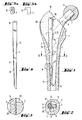
- Fig. 1 zeigt in einem Längsschnitt durch das obere Ende eines Femurknochens eine in diesem fixierte Hüftgelenkprothese mit dem erfindungsgemäßen Schaft.
- Fig. 2 ist der Schnitt 11-11 von Fig. 1.
- Fig. 3 gibt einen Bereich A aus Fig. 1 in größerem Maßstab wieder.
- Fig. 4 stellt in gleicher Ansicht wie Fig. 1 eine Ausführjngsform des keilförmigen Endstückes dar, während in
- Fig. 5a und 5b weitere Möglichkeiten für das Eingreifen eines Auszieh-Instrumentes in das obere Ende des Endstückes gezeigt sind.
- 1 shows, in a longitudinal section through the upper end of a femur bone, a hip joint prosthesis fixed in this with the shaft according to the invention.
- FIG. 2 is section 11-11 of FIG. 1.
- FIG. 3 shows an area A from FIG. 1 on a larger scale.
- Fig. 4 shows in the same view as Fig. 1, an embodiment of the wedge-shaped end piece, while in
- 5a and 5b further possibilities for engaging a pull-out instrument in the upper end of the end piece are shown.
Der blattartige Prothesenschaft (Fig. 1), der sich von seinem distalen Ende 8 nach allen Seiten konisch erweitert, setzt sich gemäß der Erfindung zusammen aus einem eigentlichen Blatt 1 und einem an dessen laterale Schmalseite angesetzten, keilförmig verlaufenden Endstück 4; sein Konus ist symmetrisch zu einer Längsmittelachse 2 ausgebildet. Die mediale Schmalseite 3 des Konus geht in einen Bogen über, der in einem Hals 6 endet. Auf diesen ist ein sich nach außen konisch verjüngender Zapfen 7 aufgesetzt, der einen kugelförmigen Gelenkkopf 9 aufnimmt. Die Achse des Zapfens 7 schneidet die Längsmittelachse 2 des Schaftes unter einem Winkel, der im wesentlichen dem Winkel zwischen dem Schenkelhals der Femurachse eines natürlichen Hüftgelenkes entspricht und im vorliegenden Fall 45° beträgt.The sheet-like prosthesis socket (FIG. 1), which widens conically from its
Das Blatt 1 und das Endstück 4 sind über eine Führung miteinander verbunden; diese besteht aus einer allseitig abgerundeten parallel zur Längsachse 2 verlaufenden Hohlkehle 11 in der lateralen Schmalseite des Blattes 1. Als Gegenstück zu dieser Hohlkehle 11 hat das Endstück 4 in der Mitte eine vorspringende kufenartige Längsleiste 12. Weiterhin umfaßt es mit seinen Rändern 13 die Seitenflanken der Hohlkehle 11. Auf diese Weise wird das Endstück 4 beim Einschlagen so geführt, daß ein seitliches Abgleiten nicht möglich ist. 1 The blade 1 and the
Wie bereits erwähnt, werden - um Kaltverschweißen zu verhindern - das Schaftblatt 1 und das Endstück 4 aus verschiedenen Materialien hergestellt, wobei das Blatt 1 beispielsweise aus einer Co-Basislegierung besteht, während das Endstück 4 aus Titan gefertigt ist; es kann jedoch auch mit einer Hartschicht auf Titan-Basis zumindest entlang der Führung belegt sein.As already mentioned, in order to prevent cold welding, the shaft plate 1 and the
Auf der lateralen Schmalseite 5 des zusammengesetzten Schaftes bzw. des Endstückes 4 reicht die Erweiterung des Konus bis auf etwa 2/3 bis 3/4 der Schafthöhe; von dort aus verläuft die laterale Schmalseite 5 des Endstückes 4 parallel zur Längsmittelachse 2.On the lateral
Die beiden Übergänge von der »Breitseite« des Endstückes 4 zur lateralen Schmalseite 5 sind über die Höhe des Konus mit je einer Verzahnung 19 versehen, die nach dem Einschlagen des Endstückes 4 widerhakenartig in die kortikale Knochensubstanz 14 eingreift und so ein unbeabsichtigtes Herausziehen des keilförmigen Endstückes 4 verhindert.The two transitions from the "broad side" of the
Für den Eingriff eines Ausziehinstrumentes hat das Endstück 4 an seinem oberen oder proximalen Ende eine Öse 15; diese kann jedoch durch andere geeignete Verbindungselemente, wie z. B. ein Gewinde 16 (Fig. 5a) oder einen hakenartigen Ansatz 17 (Fig. 5b) ersetzt sein.For the engagement of an extraction instrument, the
Wie bereits erwähnt, erlaubt die neue Schaftkonstruktion zunächst das den Gelenkkopf 9 tragende Blatt 1 in das operativ vorbereitete, spongiöse Knochengewebe 20 soweit einzuschlagen, daß das Zentrum des Gelenkkopfes 9 etwa auf der Höhe der Trochanterspitze 18 liegt, und dann das Blatt 1 bzw. der Gelenkkopf 9 festzuhalten und die Prothese durch Einschlagen des Endstückes 4 zu fixieren, wobei das Blatt 1 und das Endstück 4 miteinander zwischen einander gegenüberliegenden Bereichen des kortikalen Gewebes 14 gegeneinander verkeilt werden.As already mentioned, the new shaft construction first allows the leaf 1 carrying the joint head 9 to be driven into the surgically prepared,
Claims (6)
Priority Applications (1)
| Application Number | Priority Date | Filing Date | Title |
|---|---|---|---|
| AT82110500T ATE14187T1 (en) | 1982-01-29 | 1982-11-13 | STRAIGHT, LEAF-LIKE SHAFT FOR A JOINT REPLACEMENT. |
Applications Claiming Priority (2)
| Application Number | Priority Date | Filing Date | Title |
|---|---|---|---|
| CH541/82A CH652911A5 (en) | 1982-01-29 | 1982-01-29 | STRAIGHT, LEAF-LIKE SHAFT FOR A JOINT OPROTHESIS. |
| CH541/82 | 1982-01-29 |
Publications (2)
| Publication Number | Publication Date |
|---|---|
| EP0085147A1 EP0085147A1 (en) | 1983-08-10 |
| EP0085147B1 true EP0085147B1 (en) | 1985-07-10 |
Family
ID=4189375
Family Applications (1)
| Application Number | Title | Priority Date | Filing Date |
|---|---|---|---|
| EP82110500A Expired EP0085147B1 (en) | 1982-01-29 | 1982-11-13 | Straight flat shaft for a joint endoprosthesis |
Country Status (6)
| Country | Link |
|---|---|
| US (1) | US4530115A (en) |
| EP (1) | EP0085147B1 (en) |
| AT (1) | ATE14187T1 (en) |
| CH (1) | CH652911A5 (en) |
| DE (1) | DE3264687D1 (en) |
| ES (1) | ES268646Y (en) |
Families Citing this family (24)
| Publication number | Priority date | Publication date | Assignee | Title |
|---|---|---|---|---|
| CH658185A5 (en) * | 1983-02-10 | 1986-10-31 | Sulzer Ag | STRAIGHT, SHEET-LIKE STEM FOR A joint prosthesis. |
| DE3323131A1 (en) * | 1983-06-27 | 1985-01-03 | Waldemar Link (Gmbh & Co), 2000 Hamburg | ENDOPROTHESIS WITH A STEM TO BE ANCHORED IN THE BONE |
| DE3330062A1 (en) * | 1983-08-19 | 1985-02-28 | Waldemar Link (Gmbh & Co), 2000 Hamburg | TIE ROD FOR TUBE BONES |
| GB8401059D0 (en) * | 1984-01-16 | 1984-02-15 | Exeter University Of | Fixation of implants in bone |
| EP0170982A1 (en) * | 1984-07-26 | 1986-02-12 | Ivica Jerkovic | Joint endoprosthesis, especially hip joint prosthesis |
| FR2575064B1 (en) * | 1984-12-21 | 1989-08-18 | Caltran Maurice | HIP PROSTHESIS |
| FR2579453B1 (en) * | 1985-03-27 | 1991-06-28 | Epinette Jean Alain | FEMALE HIP PROSTHESIS COMPONENT, NOT CEMENTED |
| FR2579887A1 (en) * | 1985-04-05 | 1986-10-10 | France Implant Sarl | |
| US4775381A (en) * | 1985-05-06 | 1988-10-04 | Metripond Merleggyar | Hip prosthesis |
| DE3516203A1 (en) * | 1985-05-06 | 1986-11-06 | Metripond Mérleggyár, Hódmezövásárhely | Hip prosthesis |
| EP0222751B1 (en) * | 1985-05-23 | 1989-02-08 | Ao-Forschungsinstitut Davos | Self-locking stemmed component for a joint endo-prosthesis |
| GB2178320B (en) * | 1985-07-29 | 1989-07-19 | Finsbury | Hip implant |
| CH667199A5 (en) * | 1985-08-30 | 1988-09-30 | Sulzer Ag | METAL STRAIGHTNESS FOR A FEMUR HEAD PROSTHESIS. |
| CH669902A5 (en) * | 1986-04-30 | 1989-04-28 | Kurt Karpf | |
| FR2606997A1 (en) * | 1986-08-25 | 1988-05-27 | Gilles Crespy | SELF-BLOCKED MECHANICAL FEMALE PROSTHESIS AND METHOD OF IMPLEMENTING THE SAME |
| DE3722853A1 (en) * | 1987-07-10 | 1989-01-19 | Kernforschungsz Karlsruhe | Endoprosthesis for a femoral joint |
| US5089004A (en) * | 1988-01-19 | 1992-02-18 | Osteonics Corp. | Prosthetic implant procedure and femoral broach therefor |
| DE8816847U1 (en) * | 1988-04-01 | 1990-11-08 | Metalpraecis Berchem + Schaberg Gesellschaft für Metallformgebung mbH, 4650 Gelsenkirchen | Joint prosthesis, especially hip joint prosthesis |
| US5032133A (en) * | 1990-01-23 | 1991-07-16 | Orthovations, Inc. | Method and apparatus for expanding a shaft for use in prosthesis |
| FR2703583B1 (en) * | 1993-04-07 | 1995-06-09 | Medinov Sa | FEMALE IMPLANT FOR HIP PROSTHESIS. |
| US5458654A (en) * | 1993-07-14 | 1995-10-17 | Ao-Forschungsinstitut Davos | Screw-fixed femoral component for hip joint prosthesis |
| ITUD20030092A1 (en) * | 2003-04-30 | 2004-11-01 | Lima Lto Spa | PROSTHESIS FOR THE JOINT OF THE SHOULDER. |
| RU2591605C9 (en) | 2009-07-10 | 2016-10-27 | Милакс Холдинг С.А. | Device for hip joint and method |
| KR101856459B1 (en) * | 2010-08-31 | 2018-05-10 | 신세스 게엠바하 | Controlling the degradation of bioresorbable metal implants |
Family Cites Families (9)
| Publication number | Priority date | Publication date | Assignee | Title |
|---|---|---|---|---|
| BE560587A (en) * | ||||
| FR893401A (en) * | 1940-02-05 | 1944-06-08 | Tubular bone anchor or nail | |
| US2486303A (en) * | 1948-04-29 | 1949-10-25 | Harry Herschel Leiter | Surgical appliance for bone fractures |
| FR1278359A (en) * | 1961-01-13 | 1961-12-08 | Maison Drapier | Improvement in femoral prostheses |
| GB1511859A (en) * | 1974-12-24 | 1978-05-24 | Friedrichsfeld Gmbh | Hip-joint endoprostheses |
| DE2519488A1 (en) * | 1975-05-02 | 1976-11-18 | Anton Dr Drgalic | Bone fracture coupling pin - with two concentric rod shaped parts one cylindrical and other semi circular |
| DE2834155C3 (en) * | 1978-08-04 | 1981-09-17 | Friedrichsfeld Gmbh, Steinzeug- Und Kunststoffwerke, 6800 Mannheim | Femoral shaft for a hip joint endoprosthesis |
| DE2931750C2 (en) * | 1979-08-04 | 1986-06-19 | Howmedica International, Inc. Zweigniederlassung Kiel, 2300 Kiel | One-piece thigh part of a hip joint endoprosthesis |
| CH640407A5 (en) * | 1979-10-11 | 1984-01-13 | Sulzer Ag | Hip joint prosthesis. |
-
1982
- 1982-01-29 CH CH541/82A patent/CH652911A5/en not_active IP Right Cessation
- 1982-11-13 DE DE8282110500T patent/DE3264687D1/en not_active Expired
- 1982-11-13 AT AT82110500T patent/ATE14187T1/en not_active IP Right Cessation
- 1982-11-13 EP EP82110500A patent/EP0085147B1/en not_active Expired
- 1982-11-22 ES ES1982268646U patent/ES268646Y/en not_active Expired
-
1983
- 1983-01-03 US US06/454,991 patent/US4530115A/en not_active Expired - Fee Related
Also Published As
| Publication number | Publication date |
|---|---|
| ES268646U (en) | 1983-06-01 |
| DE3264687D1 (en) | 1985-08-14 |
| EP0085147A1 (en) | 1983-08-10 |
| CH652911A5 (en) | 1985-12-13 |
| ATE14187T1 (en) | 1985-07-15 |
| US4530115A (en) | 1985-07-23 |
| ES268646Y (en) | 1984-10-16 |
Similar Documents
| Publication | Publication Date | Title |
|---|---|---|
| EP0085147B1 (en) | Straight flat shaft for a joint endoprosthesis | |
| EP0135755B1 (en) | Stem for a hip joint prosthesis | |
| DE69728001T2 (en) | Denture with variable fit and tension distribution | |
| EP0158014B1 (en) | Hip prosthesis | |
| EP0204919B1 (en) | Prosthesis of the head of the femur | |
| EP0032165B1 (en) | Blade-shaped shaft for anchoring a hip joint prosthesis | |
| EP0159462B1 (en) | Femoral part of a total endoprosthesis for a hip joint | |
| EP0927010A1 (en) | Shinbone element of knee joint prothesis | |
| EP0169976B1 (en) | Shaft for a hip joint prosthesis conically extending from the distal part | |
| EP0366603A1 (en) | Metallic flat stem for a femoral head prosthesis | |
| DE3917285A1 (en) | Shoulder prosthesis - has condyle and acetabulum made of specified material | |
| EP0217034B1 (en) | Straight metal shaft for a femoral head prosthesis | |
| DE2839092C3 (en) | One-piece thigh part of a hip joint endoprosthesis | |
| DE10320034A1 (en) | knee prosthesis | |
| EP0145939A2 (en) | Cement-free blade-shaped shaft for a hip joint prosthesis | |
| DE9401529U1 (en) | Thigh part for a hip joint endoprosthesis | |
| DE3331191C2 (en) | Cup for a hip joint endoprosthesis | |
| EP0145938B1 (en) | Intramedullary prosthesis | |
| DE19547638A1 (en) | Thigh part of a hip joint endoprosthesis | |
| EP0238860A2 (en) | Femoral part of a endoprosthesis for a hip joint | |
| WO1984003037A1 (en) | Straight sheet-shaped pin for joint endoprosthesis | |
| CH680110A5 (en) | ||
| DE3819948C2 (en) | ||
| DE4223373C2 (en) | Endoprosthesis socket for knee joints and process for its manufacture | |
| EP0078888A1 (en) | Joint endoprosthesis having a flat and straight stem |
Legal Events
| Date | Code | Title | Description |
|---|---|---|---|
| PUAI | Public reference made under article 153(3) epc to a published international application that has entered the european phase |
Free format text: ORIGINAL CODE: 0009012 |
|
| AK | Designated contracting states |
Designated state(s): AT BE DE FR GB IT NL |
|
| 17P | Request for examination filed |
Effective date: 19830901 |
|
| ITF | It: translation for a ep patent filed | ||
| GRAA | (expected) grant |
Free format text: ORIGINAL CODE: 0009210 |
|
| AK | Designated contracting states |
Designated state(s): AT BE DE FR GB IT NL |
|
| REF | Corresponds to: |
Ref document number: 14187 Country of ref document: AT Date of ref document: 19850715 Kind code of ref document: T |
|
| REF | Corresponds to: |
Ref document number: 3264687 Country of ref document: DE Date of ref document: 19850814 |
|
| ET | Fr: translation filed | ||
| PLBE | No opposition filed within time limit |
Free format text: ORIGINAL CODE: 0009261 |
|
| STAA | Information on the status of an ep patent application or granted ep patent |
Free format text: STATUS: NO OPPOSITION FILED WITHIN TIME LIMIT |
|
| 26N | No opposition filed | ||
| PGFP | Annual fee paid to national office [announced via postgrant information from national office to epo] |
Ref country code: AT Payment date: 19891114 Year of fee payment: 8 |
|
| PGFP | Annual fee paid to national office [announced via postgrant information from national office to epo] |
Ref country code: BE Payment date: 19891117 Year of fee payment: 8 |
|
| PGFP | Annual fee paid to national office [announced via postgrant information from national office to epo] |
Ref country code: NL Payment date: 19891130 Year of fee payment: 8 |
|
| PGFP | Annual fee paid to national office [announced via postgrant information from national office to epo] |
Ref country code: GB Payment date: 19901105 Year of fee payment: 9 |
|
| PG25 | Lapsed in a contracting state [announced via postgrant information from national office to epo] |
Ref country code: AT Effective date: 19901113 |
|
| PGFP | Annual fee paid to national office [announced via postgrant information from national office to epo] |
Ref country code: FR Payment date: 19901114 Year of fee payment: 9 |
|
| ITTA | It: last paid annual fee | ||
| PG25 | Lapsed in a contracting state [announced via postgrant information from national office to epo] |
Ref country code: BE Effective date: 19901130 |
|
| PGFP | Annual fee paid to national office [announced via postgrant information from national office to epo] |
Ref country code: DE Payment date: 19901228 Year of fee payment: 9 |
|
| BERE | Be: lapsed |
Owner name: PROTEK A.G. Effective date: 19901130 Owner name: GEBRUDER SULZER A.G. Effective date: 19901130 |
|
| PG25 | Lapsed in a contracting state [announced via postgrant information from national office to epo] |
Ref country code: NL Effective date: 19910601 |
|
| NLV4 | Nl: lapsed or anulled due to non-payment of the annual fee | ||
| PG25 | Lapsed in a contracting state [announced via postgrant information from national office to epo] |
Ref country code: GB Effective date: 19911113 |
|
| GBPC | Gb: european patent ceased through non-payment of renewal fee | ||
| PG25 | Lapsed in a contracting state [announced via postgrant information from national office to epo] |
Ref country code: FR Effective date: 19920731 |
|
| PG25 | Lapsed in a contracting state [announced via postgrant information from national office to epo] |
Ref country code: DE Effective date: 19920801 |
|
| REG | Reference to a national code |
Ref country code: FR Ref legal event code: ST |