EP0084994A2 - Detektor für die Ortung einer elektromagnetischen Strahlung und Bearbeitungsvorrichtung der durch diesen Detektor gegebenen Signale - Google Patents
Detektor für die Ortung einer elektromagnetischen Strahlung und Bearbeitungsvorrichtung der durch diesen Detektor gegebenen Signale Download PDFInfo
- Publication number
- EP0084994A2 EP0084994A2 EP83400092A EP83400092A EP0084994A2 EP 0084994 A2 EP0084994 A2 EP 0084994A2 EP 83400092 A EP83400092 A EP 83400092A EP 83400092 A EP83400092 A EP 83400092A EP 0084994 A2 EP0084994 A2 EP 0084994A2
- Authority
- EP
- European Patent Office
- Prior art keywords
- cathode
- detector
- detector according
- anode
- wire
- Prior art date
- Legal status (The legal status is an assumption and is not a legal conclusion. Google has not performed a legal analysis and makes no representation as to the accuracy of the status listed.)
- Withdrawn
Links
Images


Classifications
-
- H—ELECTRICITY
- H01—ELECTRIC ELEMENTS
- H01J—ELECTRIC DISCHARGE TUBES OR DISCHARGE LAMPS
- H01J47/00—Tubes for determining the presence, intensity, density or energy of radiation or particles
- H01J47/06—Proportional counter tubes
-
- G—PHYSICS
- G01—MEASURING; TESTING
- G01T—MEASUREMENT OF NUCLEAR OR X-RADIATION
- G01T1/00—Measuring X-radiation, gamma radiation, corpuscular radiation, or cosmic radiation
- G01T1/29—Measurement performed on radiation beams, e.g. position or section of the beam; Measurement of spatial distribution of radiation
- G01T1/2914—Measurement of spatial distribution of radiation
- G01T1/2921—Static instruments for imaging the distribution of radioactivity in one or two dimensions; Radio-isotope cameras
- G01T1/2935—Static instruments for imaging the distribution of radioactivity in one or two dimensions; Radio-isotope cameras using ionisation detectors
Definitions
- the present invention relates to a detector intended to locate the point of impact of electromagnetic radiation.
- X-ray diffraction used for the analysis of atomic structures in crystallography, metallurgy and biological chemistry, uses the spatial distribution of the secondary radiation from the sample.
- the usual method uses a point detector, and we record the number of X photons it detects during its movements
- Proportional gas meters are also known which allow each individual photon to be counted slowly and its position to be located.
- the best-developed current location meters are one-dimensional and are sensitive on a narrow rectilinear strip with a length of approximately 50 mm.
- Such a counter was produced for the first time by BORKOWSKI and KOPP (Rev. Sci. Instrum. N ° 39, page 1515, 1968).
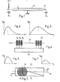
- this counter includes a resistant quartz wire 10 connected to the positive terminal of a high voltage source. This wire, which serves as an anode, is covered with a layer of carbon,
- a resistance-capacitance line with a distributed constant 12 is thus produced.
- the location of the point of impact of the photon on this line is obtained by measuring the rise times of the signals S 1 and S 2 which result therefrom and which are collected at the ends A and B of the wire 10.
- the signals S 1 and S 2 will have the appearance shown in FIGS. 2 and 3: the rise time of the signal S 1 is very low and that of the signal S 2 is longer.
- This counter which has the advantage of great simplicity, is on the other hand very fragile because the carbon layer can be easily destroyed if it is exposed to an intense beam of X-ray radiation. This counter is therefore at the mercy of a mishandling.
- FIG. 4 This counter is constituted by a central anode wire 13 made of metal, for example made of golden tungsten brought to a high potential.
- the cathode located on either side of the wire 13 is at zero potential. It consists of a plexiglass cell whose bottom is divided into parallel strips 14 1 , 14 2 ... 14 n electrically conductive.
- Each of said bands is connected to a line with distributed constants 16 also fragmented.
- a gas stream of argon and methane passes through the cell.
- the advantages of this detector are good robustness due to its metal anode wire, a counting speed resulting from the low line time constant 16 and good linearity.
- the response curve is strewn with accidents which are due to parasitic reflections at each connection socket on a cathode. This drawback makes the detector difficult to use and that is why it has not been industrialized.
- This detector always has an anode wire 18, but its cathode is made up of two pieces 20, 22 in the form of right triangles, arranged in contact according to their hypotheses, as shown in the figure 5.
- a photon falling at point C of the anode influences, on the half-cathodes 20, 22, the shaded areas 24, 26 whose surfaces of course depend on the position of C relative to the ends of the anode.
- the signals S 1 and S 2 collected on the half-cathodes have the paces shown in FIGS. 6 and 7. It can be seen that they have the same shape but different amplitudes. This variation in amplitude depends on the area influenced. We thus have a means of locating the point of impact C.
- This counter is robust and has a very flat response curve as well as good linearity, but its counting rate is limited due to its principle. Indeed, the measurement of the amplitude for a photon X can be marred by an error by the presence of another photon X arrived a few moments earlier or later.
- the object of the present invention is to remedy the aforementioned drawbacks of the counters of the signaled prior art and for this purpose proposes a counter with radiation localization which is characterized in that it essentially comprises at least one anode wire surrounded by a cathode resistive, of suitable shape, the assembly being immersed in a gaseous atmosphere which constitutes the radiation detector element.
- the cathode is constituted by a coil of metallic resistant wire, which is crossed axially by the anode wire.
- the cathode wire and the capacitance formed by the shielding which surrounds it constitute a distributed constant sensor.
- the wire is chosen with a very small diameter compared to the pitch of the winding, so that it absorbed only a negligible part of the incident radiation.
- the detector according to the invention comprises two supports in the form of half-cylinders, provided on their cylindrical wall with a pitch thread corresponding to that desired for the winding, said supports being fixed by their ends on a mounting frame which keeps them apart and parallel, with their cylindrical wall facing outwards, the cathode wire being wound around the thread of said supports and the anode wire being stretched inside the winding between two borne terminals by the carcass.
- the supports are produced from a single cylindrical rod on which a thread of pitch equal to that desired for the winding has been executed and which has been cut in two along a diametrical plane. This gives regular spacing of the turns of the winding.
- the cathode consists of a resistive tubular surface, inside which the anode wire passes axially.
- the detector makes it possible to correct a linearity error of the response curve, or to obtain a desired response curve.
- a variable pitch winding is produced. It is also possible to vary the resistance of the conductive layer of the cathode, in the case where it consists of a layer.
- the principle of the invention can be used for the production of a two-dimensional detector.
- a detector comprises two coiled cathodes, arranged at 90 ° relative to each other and nested one inside the other, a sheet of anode wires being placed at the inside the internal winding.
- the signals corresponding to the two dimensions are collected at the terminals of the cathodes.
- the two-dimensional detector comprises a wound cathode in which is nested perpendicularly an anode also wound in a flattened structure and brought to the positive potential of the high voltage. The photon is identified along one axis by the cathode and along the other axis by the anode.
- a two-dimensional detector can also be produced by using two elementary cathodes superimposed and oriented perpendicularly to one another, each of them receiving a layer of anode wires.
- the detector shown diagrammatically in FIG. 8 comprises, in principle, a cathode 30 constituted by a coil of resistant metallic wire, crossed in the axial direction by an anode wire 32 which is connected to the positive terminal of a source of high tension. It is also possible to have several anode wires inside the winding.
- the entire cathode and anode is enclosed in an enclosure 34 (FIG. 9) filled with a gaseous atmosphere 36 comprising 90% xenon or argon and 10% methane, in the case of detection of X photons.
- the detection cell shown in FIG. 10 comprises an elongated metal carcass 38 ending at its ends by portions 40, 42, profiled in I.
- two insulating supports 44, 46 in the form of half-cylinders which have a thread of small pitch on their cylindrical wall.
- the supports are therefore parallel and spaced apart by a distance equal to the thickness of said central branches.
- a metal anode wire 48 which hooks by its ends to two terminals 50, 52 carried respectively by two insulating structures 54, 56, fixed on said end portions 40, 42 of the carcass.
- One of the terminals is connected to the positive terminal of a high voltage source.
- the anode wire is stretched by spring blades 58.
- a cathode wire 60 is wound on the supports 44, 46 by passing it through the successive threads. This gives a very regular winding with tight turns.
- the ends of the cathode wire are connected to terminals 62, 64 to which the signals S 1 and S 2 induced by the anode wire 48 are collected during a photon impact. Since the cathode wire 60 completely surrounds the anode wire 48, it fully captures the influence signal induced by the latter. As a result, the signal-to-noise ratio of the preamplifiers obtained during the processing of the signals S and S 2 , is significantly higher than that obtained with known detectors. As a result, the resolution is also improved. In addition, due to the low capacity of the wound cathode, a high counting speed is obtained.
- FIG. 11 which comprises a tubular cathode 66 in which an anode wire 68 is disposed.
- the cathode can be reduced to a portion of tube 69 (FIG. 12) or even to a plate 70 (FIG. 13).
- the cathode is made of any material which may not elongate during winding, for example an alloy of chromium and nickel.
- the anode can be made of molybdenum or tungsten, possibly gilded.
- FIG. 14 represents the special resolution obtained at any point A of the cell, with a tubular cathode cell, of the type shown in FIG. 10, the detector being placed in front of a slot 50 ⁇ m wide and 8 mm height.
- the position d of the impsot point on the wire anode is plotted on the abscissa and the number of impacts N recorded at the point considered is plotted on the ordinate.
- the resolution thus obtained is between 150 and 250 ⁇ depending on the value of the filling pressure of the enclosure 36 (FIG. 9). This resolution remains practically uniform over a cell length of 45 mm.
- Figure 15 shows the energy resolution with a tubular cathode cell with a diffracted beam on a lithium fluoride crystal serving as a monochromator.
- the resolution is 15% and this value is constant at less than 1% over a cell length of 45 mm.
- the maximum counting speed is between 30,000 and 50,000 counts per second and the total electronic dead time included is around 10 ⁇ s,
- a great feature of this counter is the very small variation in spatial resolution as a function of the height of the localized beam. Between 2 and 8 mm in height, the variation is less than 10%. This is due to the great symmetry of the counter and to the fact that the incident beam is parallel to the cathode wires, as shown in FIG. 16.
- a beam 72 emitted by an X-ray tube 74 is diffracted by a sample 76.
- the reference 78 shows the shape of the diffracted beam.
- This advantage is particularly interesting because it determines the conditions of the experiment, such as the duration of the measurement, the detected flux being maximum with a large slit height.
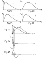
- the cell of FIG. 10 is comparable to a line with distributed constant, as represented in FIG. 17, in which r 1 to r n are the resistances of the turns of the cathode 60 and C to C n are the capacitances of these turns relative to the shielding.
- Reference 48 represents the anode wire.
- the shape of the signals S and S 2 collected at the ends of the cathode 60 depends on the position of the impact of the photon X. Thus, if the photon arrives at A in FIG. 18, the signal S will have a very short rise time , while the signal S 2 which will have been integrated by the line between A and C will take a very long time to go up.
- the signals thus collected are respectively represented in FIGS. 19, 20.
- the signals S 1 and S 2 of FIG. 23 are shaped by double differentiation, which makes it possible to obtain the signals e 1 and e 2 represented in FIGS. 24, 25
- the difference t 2 -t 1 between the zero crossing times of the signals e 2 and e 1 represents the position information of the detected radiation.
- FIG. 26 shows the equivalent electrical diagram of a detection cell in which the shield 80 has a shape which is suitably curved to vary the distributed capacitance of the cell, with a view to correcting a linearity error in the response curve of the cell or get a desired response curve.
- the response curve can also be corrected by using a wound cathode with variable pitch 82, as shown in FIG. 27, or even by varying the resistance of the conductive layer, when the detector is thus produced.
- correction methods can be implemented to correct the parallax effect on a diffraction goniometer by giving the detector a pseudo-radius of curvature, as shown in FIG. 28.
- a beam 84 of X-rays is diffracted by a sample 86 along a goniometric circle 88 tangent to the anode wire 90 of the detector.
- the shielding 92 of the latter is given a curvature calculated so that the parallax 94 is corrected.
- the detector according to the invention can also be used for the detection of ⁇ radiation and neutrons, only the nature of the detector gas changing in both cases.
- two wound cathodes 96, 98 are fitted one into the other, so that the planes of their turns are perpendicular.
- a layer of anode wires 100 is placed inside the internal cathode 98.
- the signals corresponding to the two dimensions are collected at the terminals X, Y of the cathodes.
- the two-dimensional detector shown in FIG. 30 comprises a single wound cathode 102 and an anode 104 also wound but of very flat structure.
- the anode is inserted into the cathode so that its turns are perpendicular to those of the cathode.
- the anode is brought to the positive potential of the high voltage.
- the photon is located along an X axis by the cathode and along the Y axis by the anode.
- the anode can be replaced by a strong metallic wire folded in a ziczag.
- the two-dimensional detector of FIG. 31 comprises two elementary cells superimposed and oriented so that the turns of their respective cathode 106, 108 are perpendicular to each other. Indeed, since the photon is detected by the Compton effect, that is to say by energy loss along the path of the photon, the latter after having crossed the first cell 106 still has energy to produce a signal in the second cell 108.
- the thickness of each cell can be adjusted so that the electrical signal is equivalent in each cell. If the desired surface is large, it will be necessary to have several anode fila in each cell to ensure a sufficient electric field for the photons detected in the region of the edges.
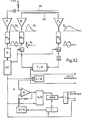
- FIGS. 32 and 33 the diagram of the electronic assembly of a device for processing the signals supplied by the detector according to the invention.
- the signal from the anode wire 48 is amplified by a preamplifier E, then shaped by the shaping device M 3 by double differentiation and integration of the signal S 3 supplied by the preamplifier E We then obtain the signal e 3 . This then passes through the energy discrimination circuit D.
- the signals from the ends of the cathode 60 are amplified by the preamplifiers P 1 and P2 which supply the signals S 1 and S 2 . These signals are shaped by double differentiation in the devices M 1 and M 2 . The zero crossing of signals e 1 and e 2 from M 1 and M 2 is detected by the comparators C 1 and C 2 . The signal from comparator C 2 is delayed by circuit R.
- the signal supplied by C 1 triggers a time-amplitude converter T / A while the signal from R stops said converter. An amplitude representing the position of the X photon detected by the counter is then obtained at the output of the latter.
- An E / B sampler-blocker allows the value contained in the T / A converter to be taken in order to release it.
- An analog-digital A / D converter converts the value contained in the sampler-blocker into a digital value which also represents the position of the photon X in the counter.
- the signal from the discrimination circuit D is received by an LC coordination logic, the output of which is connected to the sampler-blocker E / B and to the analog-digital converter A / D.
- Said logic makes it possible to synchronize the assembly, and in particular it standardizes the dead time of the system to a fixed value (from the appearance of the anode pulse until the transfer of the time-amplitude converter T / A in the E / B sampler-blocker). This has the effect of obtaining, over the entire length of the cell, an equal density of probability of treatment, for each event treated, and consequently a rectilinear response curve.
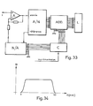
- the response curve of the counter has the shape shown in FIG. 34, on which the length of the cell is plotted on the abscissa and the number of strokes N per second, on the ordinate.
- Figure 33 explains in more detail the lower part of the diagram of Figure 32.
- the analog-digital converter A / D with successive approximations, if it allows a high speed, on the other hand presents a serious disadvantage as for the quality of the curve obtained. This is due to the unevenness of the converter steps. In an A / D converter with 4096 steps (12 bits), these faults are manifested mainly at the following crossover points: (2047, 2048), (1023, 1024), (511, 512), (255, 256) , (127, 128), etc ...
- the counter C is also connected to a binary adder ADD, so that it makes it possible to add the value which it contains to that given by the analog-digital converter A / D which it is a question of correcting.
- the output voltage of the digital / analog converter D / A is subtracted by a differential amplifier A from the signal to be measured S; it follows that the analog value subtracted from the input to the signal to be measured S is added in binary at the output of the analog-digital converter A / D by the adder ADD.
- the gain of the differential amplifier A should be adjusted so that the value subtracted is equal to the value added at the output by the adder.
Landscapes
- Physics & Mathematics (AREA)
- Health & Medical Sciences (AREA)
- Life Sciences & Earth Sciences (AREA)
- General Physics & Mathematics (AREA)
- High Energy & Nuclear Physics (AREA)
- Molecular Biology (AREA)
- Spectroscopy & Molecular Physics (AREA)
- Measurement Of Radiation (AREA)
- Nuclear Medicine (AREA)
Applications Claiming Priority (2)
| Application Number | Priority Date | Filing Date | Title |
|---|---|---|---|
| FR8201092 | 1982-01-25 | ||
| FR8201092A FR2520514B1 (fr) | 1982-01-25 | 1982-01-25 | Detecteur pour la localisation d'un rayonnement electromagnetique et dispositif de traitement des signaux fournis par ledit detecteur |
Publications (2)
| Publication Number | Publication Date |
|---|---|
| EP0084994A2 true EP0084994A2 (de) | 1983-08-03 |
| EP0084994A3 EP0084994A3 (de) | 1983-08-17 |
Family
ID=9270276
Family Applications (1)
| Application Number | Title | Priority Date | Filing Date |
|---|---|---|---|
| EP83400092A Withdrawn EP0084994A3 (de) | 1982-01-25 | 1983-01-14 | Detektor für die Ortung einer elektromagnetischen Strahlung und Bearbeitungsvorrichtung der durch diesen Detektor gegebenen Signale |
Country Status (3)
| Country | Link |
|---|---|
| US (1) | US4598204A (de) |
| EP (1) | EP0084994A3 (de) |
| FR (1) | FR2520514B1 (de) |
Families Citing this family (1)
| Publication number | Priority date | Publication date | Assignee | Title |
|---|---|---|---|---|
| FR2792772B1 (fr) * | 1999-04-20 | 2001-05-18 | Commissariat Energie Atomique | Chambre d'ionisation, chaine de mesure d'activite d'un gaz emetteur de rayonnement beta et procede de mise en oeuvre de celle-ci |
Family Cites Families (6)
| Publication number | Priority date | Publication date | Assignee | Title |
|---|---|---|---|---|
| GB1179407A (en) * | 1966-02-28 | 1970-01-28 | Atomic Energy Authority Uk | Improvements in or relating to Geiger-Mueller Counters |
| GB1179406A (en) * | 1966-02-28 | 1970-01-28 | Atomic Energy Authority Uk | Improvements in or relating to Proportional Counters |
| US3517194A (en) * | 1968-10-24 | 1970-06-23 | Atomic Energy Commission | Position-sensitive radiation detector |
| US3911279A (en) * | 1973-05-17 | 1975-10-07 | Ball Brothers Res Corp | Position sensitive multiwire proportional counter with integral delay line |
| FR2255702B1 (de) * | 1973-12-21 | 1976-10-08 | Commissariat Energie Atomique | |
| DE2649192A1 (de) * | 1976-10-28 | 1978-05-11 | Braun M Gmbh | Ortsempfindliches proportionalzaehlrohr |
-
1982
- 1982-01-25 FR FR8201092A patent/FR2520514B1/fr not_active Expired
-
1983
- 1983-01-14 EP EP83400092A patent/EP0084994A3/de not_active Withdrawn
-
1985
- 1985-03-25 US US06/715,948 patent/US4598204A/en not_active Expired - Fee Related
Also Published As
| Publication number | Publication date |
|---|---|
| US4598204A (en) | 1986-07-01 |
| FR2520514B1 (fr) | 1985-10-25 |
| FR2520514A1 (fr) | 1983-07-29 |
| EP0084994A3 (de) | 1983-08-17 |
Similar Documents
| Publication | Publication Date | Title |
|---|---|---|
| EP0678896B1 (de) | Medizinischer Bilderzeugungsvorrichtung mittels ionisierender Röntgen- oder Gamma Strahlungen niedriger Dosis | |
| EP0763751B1 (de) | Verfahren und Vorrichtung zur Korrektur von Signalen in der Gammaphotonenspektroskopie | |
| Tougaard et al. | Concentration depth profiles by XPS; A new approach | |
| FR2961904A1 (fr) | Procede d'identification de materiaux a partir de radiographies x multi energies | |
| EP0810631A1 (de) | Röntgenbilderzeugungsvorrichtung hoher Auflösung | |
| EP2951565A1 (de) | Vorrichtung und verfahren zum zerstörungsfreien prüfen von reifen durch tomografie | |
| EP1004040B1 (de) | Vorrichtung zur spektrometrischen messung im gebiet der detektion von gammaphotonen | |
| EP0851512A1 (de) | Halbleiterstrahlungsdetektor mit hohem Widerstand für ionisierende Strahlung | |
| FR2790100A1 (fr) | Detecteur bidimensionnel de rayonnements ionisants et procede de fabrication de ce detecteur | |
| CA2122067C (fr) | Procede et dispositif d'etalonnage pour un ensemble de mesure du profil transversal d'epaisseur d'un produit plat | |
| EP3432035A1 (de) | Verfahren zur verarbeitung eines impulses, der von einem detektor für ionisierende strahlung erzeugt wird | |
| WO2000063723A1 (fr) | Detecteur bidimensionnel de rayonnements ionisants et procede de fabrication de ce detecteur | |
| EP0084994A2 (de) | Detektor für die Ortung einer elektromagnetischen Strahlung und Bearbeitungsvorrichtung der durch diesen Detektor gegebenen Signale | |
| EP0615274A1 (de) | Bilderzeugungsvorrichtung von ionisierenden Partikeln mittels einer Mehrdraht-Proportionalkammer | |
| EP0136238B1 (de) | Vorrichtung zur Messung der Nähe einer metallisch leitenden Oberfläche | |
| EP0907086B1 (de) | Vorrichtung zum Messen der Aufsteigszeit von verrauschten Signalen von Gamma- oder Röntgendetektoren | |
| WO2014044982A2 (fr) | Procede d'analyse par diffractometrie et diffractometre associe, particulierement adaptes a des echantillons comportant plusieurs couches de materiaux | |
| CA2178467A1 (fr) | Procede de controle en temps reel du debit de dose rayonnements ionisants et dispositif pour sa mise en oeuvre | |
| EP2787891B1 (de) | Verfahren zur radiographie einer last zur ausführung einer erkennung | |
| FR2766269A1 (fr) | Sonde a courants de foucault pour le controle non destructif de la paroi d'un tube et procede de traitement des signaux de la sonde | |
| EP0075517B1 (de) | Vorrichtung zur nicht-destruktiven Messung der Wanddicke eines hohlen Werkstücks | |
| FR2503381A1 (fr) | Detecteur de rayonnement | |
| FR2602058A1 (fr) | Detecteur a gaz utilisant une anode a microbandes | |
| EP3749981A1 (de) | System zur charakterisierung eines strahls geladener teilchen und maschine zur erzeugung eines strahls geladener teilchen mit einem solchen system | |
| FR2761195A1 (fr) | Diode a vide a densite de courant de saturation elevee et temps de reponse rapide pour la detection de rayonnements electromagnetiques |
Legal Events
| Date | Code | Title | Description |
|---|---|---|---|
| PUAI | Public reference made under article 153(3) epc to a published international application that has entered the european phase |
Free format text: ORIGINAL CODE: 0009012 |
|
| PUAL | Search report despatched |
Free format text: ORIGINAL CODE: 0009013 |
|
| AK | Designated contracting states |
Designated state(s): AT CH DE GB IT LI NL |
|
| AK | Designated contracting states |
Designated state(s): AT CH DE GB IT LI NL |
|
| 17P | Request for examination filed |
Effective date: 19831231 |
|
| 17Q | First examination report despatched |
Effective date: 19860630 |
|
| STAA | Information on the status of an ep patent application or granted ep patent |
Free format text: STATUS: THE APPLICATION HAS BEEN WITHDRAWN |
|
| 18W | Application withdrawn |
Withdrawal date: 19860915 |