EP0084741A2 - Device for constraining reared birds for their insemination - Google Patents
Device for constraining reared birds for their insemination Download PDFInfo
- Publication number
- EP0084741A2 EP0084741A2 EP82400786A EP82400786A EP0084741A2 EP 0084741 A2 EP0084741 A2 EP 0084741A2 EP 82400786 A EP82400786 A EP 82400786A EP 82400786 A EP82400786 A EP 82400786A EP 0084741 A2 EP0084741 A2 EP 0084741A2
- Authority
- EP
- European Patent Office
- Prior art keywords
- birds
- board
- fixed
- adjustable
- clamp
- Prior art date
- Legal status (The legal status is an assumption and is not a legal conclusion. Google has not performed a legal analysis and makes no representation as to the accuracy of the status listed.)
- Granted
Links
- 230000009027 insemination Effects 0.000 title claims abstract description 15
- 230000000452 restraining effect Effects 0.000 claims abstract description 17
- 238000003306 harvesting Methods 0.000 claims abstract description 8
- 239000003039 volatile agent Substances 0.000 claims abstract description 8
- 210000000582 semen Anatomy 0.000 claims abstract description 6
- 241000271566 Aves Species 0.000 claims description 28
- 229910000746 Structural steel Inorganic materials 0.000 claims description 3
- 230000006835 compression Effects 0.000 claims description 3
- 238000007906 compression Methods 0.000 claims description 3
- 241000272458 Numididae Species 0.000 claims description 2
- 241000286209 Phasianidae Species 0.000 claims description 2
- 235000014443 Pyrus communis Nutrition 0.000 claims description 2
- 239000000463 material Substances 0.000 claims description 2
- 238000006073 displacement reaction Methods 0.000 abstract 1
- 241001465754 Metazoa Species 0.000 description 4
- 238000000034 method Methods 0.000 description 3
- 230000000717 retained effect Effects 0.000 description 2
- 239000007787 solid Substances 0.000 description 2
- 235000004443 Ricinus communis Nutrition 0.000 description 1
- 240000000528 Ricinus communis Species 0.000 description 1
- 210000003608 fece Anatomy 0.000 description 1
- 238000007373 indentation Methods 0.000 description 1
- 230000000149 penetrating effect Effects 0.000 description 1
- 238000009374 poultry farming Methods 0.000 description 1
- 210000002105 tongue Anatomy 0.000 description 1
Images


Classifications
-
- A—HUMAN NECESSITIES
- A61—MEDICAL OR VETERINARY SCIENCE; HYGIENE
- A61D—VETERINARY INSTRUMENTS, IMPLEMENTS, TOOLS, OR METHODS
- A61D3/00—Appliances for supporting or fettering animals for operative purposes
-
- A—HUMAN NECESSITIES
- A01—AGRICULTURE; FORESTRY; ANIMAL HUSBANDRY; HUNTING; TRAPPING; FISHING
- A01K—ANIMAL HUSBANDRY; CARE OF BIRDS, FISHES, INSECTS; FISHING; REARING OR BREEDING ANIMALS, NOT OTHERWISE PROVIDED FOR; NEW BREEDS OF ANIMALS
- A01K37/00—Constraining birds, e.g. wing clamps
Definitions
- the present invention relates to a device for keeping high birds, used for insemination of female birds such as hens, guinea fowl, turkeys and / or for collecting semen from males.
- an object of the present invention is to provide a device for restraining birds which leaves them close to their cages, supporting them and now to allow the operator to intervene. with both hands to harvest or inseminate. Said restraining device must also allow the operator to move along the batteries at a suitable distance and at the various levels necessary.
- the volatile retaining and guiding member is a board in the form of a slide arranged below the volatile containment means and whose inclination is adjustable relative to the carriage.
- the operator having placed the carriage in position in front of a battery, grasps a bird by its legs, places it against the board and fixes it by its legs in the means of restraint, practices insemination and unblocks said said means, the bird then falling into its cage without any help from the operator.
- the board comprises lateral flanges and slightly recessed imprints, provided in a number equal to that of the means for restraining the birds, the flanges and / or the imprints serving to guide the birds falling under the action of their own weight when released from the means of restraint.
- the containment means for each bird are suitably formed by vertical clamps, one of which is fixed and the other of which is movable in an adjustable support on a horizontal angle fixed to the board.
- the clamps are constituted by a fixed shoe secured to the adjustable support and by a shoe movable in a vertical plane around a horizontal axis under the action of a return spring, the movable shoe comprising a recessed part such that, in its closed position when it is applied against the fixed shoe, it delimits with the latter a roughly pear-shaped opening in vertical cross section.
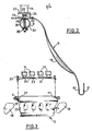
- the carriage 1 can move in front of the superimposed batteries 8 of individual cages 9 containing the birds - hens for example - parallel to said cages being guided by castors 10 fixed on the extensions of horizontal arms 11 mounted at the top of the carriage 1
- the latter further comprises a plate 12 suitable for carrying the operator and which can be placed at different heights, for example on lateral uprights, such as 13, adjustable in height in a conventional manner not shown on the vertical uprights 3, which allows the operator to be seated or standing depending on the level of the battery concerned.
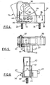
- FIGS. 2 and 3 for the sake of clarity of the drawing, only the member 6 for retaining and guiding the volatiles and means of restraint of the latter, which are integral with it as will be described below, has been shown.
- the member 6 for retaining and guiding the birds is constituted by a curved board having a shape of a slide, the central part of which can have indentations 15 (in dotted lines) slightly hollow allowing better support and positioning of the birds and whose edge lower 16 is vertical (solid line) or may include a kind of gutter 17, for example for collecting the droppings of birds.
- the board 6 further comprises removable lateral flanges 18, fixed to the lateral sides of the board by tongues 19 penetrating into holes 20 of said board whose width corresponds to a determined number (here four) of birds.
- This clipboard is disposed below the means 14 for containing the volatiles, described below in detail, and which are fixed in an adjustable manner laterally in a slide 21 of an elongated and flat horizontal angle 22 secured in a conventional manner not shown, of the horizontal part 23 of the board 6.
- the restraining means 14 are fixed to the angle iron 22 by threaded rods 24, situated at their lower part and passing through the slide 21, and nuts 25.
- the angle 22 is made integral with the horizontal part of the board 6, by fixing members such as bolts 26 passing through holes not shown formed in the preferably curved ends (Fig. 3) of the angle and elongated slots 27 formed in the board 6, so that the latter can be adjusted in position relative to the support tube 5 by means of the tightening of knurled nuts 28.
- the tube 5 may comprise, to the right of each bolt 26, an upper hole 29 of a diameter just sufficient for the passage of the rod of the bolt 26, while the lower hole 30 is in the form of an elongated lumen, for example, oval.
- These means 14 essentially consist of a clamp 31 fixed in the form of a vertical shoe or solid pad and of a movable clamp 32 in the form of a vertical shoe or solid pad, said clamps preferably being made of a material which does not injure volatiles, such as rubber.
- the fixed clamp 31 is secured to a support 33 in the form of a U-shaped angle iron, in cross section having lateral flanges 34, of a height less than that of the clamps 31, 32, using bolts 35.
- the movable clamp 32 can pivot around a horizontal axis 36 fixed in free rotation at the other end of the support 33, being retained by a pin 37, between a closed position (shown in solid lines) and an open position (shown in dashed line in FIG. 4), said clamp flowing freely between the flanges 34 of the support 33.
- the movable clamp 32 has a transverse recess 38 of suitable flared shape, while the surface of the clamp 31 facing the clamp 32 has a slightly curved profile 39.
- the lower edge of the clamp 32, located below the opening 38, has a shape adapted to that of profile 39, so that in the closed state, the two clamps delimit an opening preferably in the shape of a pear in cross section making it possible to accommodate the two legs of a bird.
- the restraining means 14 comprise a return spring 40 used to permanently push back in the open position the clamp 32 which is partially wound around the axis 36 and comprises an upper branch 41, of which a horizontal bent part 42 is integral rigid lateral flanges 43, enclosing the clamp 32 and of which the latter: is integral, and a lower branch 44 fixed in one of the flanges 33, between which the clamp 32 pivots.
- a return spring 40 used to permanently push back in the open position the clamp 32 which is partially wound around the axis 36 and comprises an upper branch 41, of which a horizontal bent part 42 is integral rigid lateral flanges 43, enclosing the clamp 32 and of which the latter: is integral, and a lower branch 44 fixed in one of the flanges 33, between which the clamp 32 pivots.
- said containment means 14 provided for each bird comprises a system 45 for locking the movable clamp 32 in the closed position.
- This system shown in more detail in Figure 7, consists of a rod 46 mounted with the possibility of longitudinal sliding in translation perpendicular to the clamps 31, 32, in a molded block 47 fixed to the support 33 of the clamps by means of bolts 48.
- the connecting rod 46 has an internal end 49 projecting in the form of a stud engaging in the closed state in a corresponding cavity 50 formed in the lateral flange 43 of the movable clamp 32, being subjected to the permanent action of a pressure spring 51 interposed between a shoulder 52 of the link and the bottom 53 of the molded block.
- FIG. 8 shows an alternative embodiment of the locking system of the movable clamp, which here consists of a link 55, the inner end of which comprises a hemispherical cavity 56, capable of partially accommodating a ball 57 partly U housed in a corresponding cavity 58 formed in the flange 43, said ball being retained by appropriate means not shown in the flange 43 or which can even be replaced, as well as the cavity 58 by a simple hemispherical bulge (not shown) in the flange 43.
- the mobile clamp 32 is released in the same manner as above by pulling on the ring 53.
- FIG. 10 the case is shown where the means 14 for retaining volatile dice are joined together, at the outer ends of their links 63, 64, by a bar 65 articulated by any suitable known means, allowing either to release two volatiles simultaneously, or to release one, while keeping the other in the second compression system.
- the board 6 could not be rigidly secured to the angle 22, but be articulated by any known suitable means, the adjustment in the inclined position then being carried out using devices (not shown) screwable for example on the uprights of the carriage 1.
- the clamp 31 can be adjusted in translation relative to the clamp 32, angularly movable, in order to vary the width of the recess 38 to adapt the latter to the size of the legs of the birds.
- This adjustment can be carried out easily by providing lights 33 in the support allowing the adjustment of the clamp 31 which could thus be fixed by bolts in any relative position relative to the clamp 32.
Abstract
- L'invention concerne un dispositif de contention d'oiseaux élevés, servant à l'insémination et à la récolte de semence de ces derniers. - Le problème technique posé consiste à fournir un tel dispositif réduisant les déplacements et les manipulations de l'opérateur qui l'autorise à travailler seul et à bien synchroniser ses mouvements. - Suivant l'invention, il comprend un chariot mobile (1) guidé par rapport aux batteries contenant les volatiles et portant des moyens réglables et verrouillables (14) de contention temporaire de ces derniers ainsi qu'un organe (6) de retenue des volatiles et de guidage de ces derniers lors de leur relâchement après l'opération d'insémination ou de récolte de semence dont sont solidaires les moyens (14) de contention. - L'utilisation principale de l'invention réside dans l'insémination des volatiles élevés.- The invention relates to a device for keeping high birds, used for insemination and for the harvesting of their semen. - The technical problem posed consists in providing such a device reducing the displacements and the manipulations of the operator who authorizes him to work alone and to synchronize his movements well. - According to the invention, it comprises a mobile carriage (1) guided relative to the batteries containing the birds and carrying adjustable and lockable means (14) for temporarily restraining them as well as a member (6) for retaining the birds and guiding the latter when they are released after the insemination or semen harvesting operation with which the means (14) for restraint are attached. - The main use of the invention lies in the insemination of high volatiles.
Description
La présente invention concerne un dispositif de contention d'oiseaux élevés, servant à l'insémination de volatiles femelles tels que poules, pintades, dindes et/ou à la récolte de semence des mâles.The present invention relates to a device for keeping high birds, used for insemination of female birds such as hens, guinea fowl, turkeys and / or for collecting semen from males.
En aviculture, l'insémination artificielle est l'une des méthodes de reproduction utilisées couramment. Elle peut être pratiquée soit au sol, soit dans des batteries de cages individuelles ou collectives. Un problème important se pose au niveau de la quantité de main-d'oeuvre nécessaire pour effectuer la récolte ou l'insémination qui est notamment déterminée par la méthode et la technologie mises en oeuvre.In poultry farming, artificial insemination is one of the commonly used reproduction methods. It can be practiced either on the ground, or in individual or collective cage batteries. An important problem arises in terms of the amount of labor required to carry out the harvesting or insemination, which is notably determined by the method and technology used.
Actuellement, des appareils portatifs d'insémination et les méthodes modernes de travail permettent de n'utiliser souvent qu'un seul opérateur pour un nombre relativement important de volatiles. Mais ce dernier doit effectuer un certain nombre de mouvements tels que saisie, contention, récolte, insémination, etc... qui prennent du temps.Currently, portable insemination devices and modern working methods often make it possible to use only one operator for a relatively large number of birds. But the latter must carry out a certain number of movements such as seizure, restraint, harvest, insemination, etc ... which take time.
Ce problème est crucial dans le cas où l'on envisage l'insémination des poules, car la rentabilité de l'opération est déterminée par la rapidité du travail qui, pour être efficace, doit être aussi peu contraignant pou:r l'opérateur que pour les animaux. Ceci suppose que l'opérateur soit libéré des problèmes de contention et que ses déplacements ainsi que ceux des volatiles soient aussi limités que possible (gain de temps).This problem is crucial when considering the insemination of hens, because the profitability of the operation is determined by the speed of work which, to be effective, must be as little restrictive for the operator as for animals. This supposes that the operator is freed from the problems of restraint and that his movements as well as those of the birds are as limited as possible (time saving).
C'est pourquoi, un but de la présente invention est de fournir un dispositif de contention des volatiles qui laisse ces derniers près de leurs cages, en les soutenant et maintenant pour permettre à l'opérateur d'intervenir avec ses deux mains pour récolter ou inséminer. Ledit dispositif de contention doit aussi permettre à l'opérateur de se déplacer le long des batteries à distance convenable et aux différents niveaux nécessaires.This is why, an object of the present invention is to provide a device for restraining birds which leaves them close to their cages, supporting them and now to allow the operator to intervene. with both hands to harvest or inseminate. Said restraining device must also allow the operator to move along the batteries at a suitable distance and at the various levels necessary.
Ce problème est résolu par la présente invention à l'aide du dispositif décrit plus haut, caractérisé par un chariot mobile guidé par rapport aux batteries et portant les dispositifs réglables de soutien et de contention des animaux. L'organe de retenue et de guidage des volatiles, lors de leur relâchement après l'opération d'insémination ou de récolte de semence, est solidaire des moyens de contention.This problem is solved by the present invention using the device described above, characterized by a mobile carriage guided relative to the batteries and carrying the adjustable devices for supporting and restraining animals. The volatile retaining and guiding member, when they are released after the insemination or semen harvesting operation, is secured to the restraining means.
Selon une variante préférée de réalisation de l'invention, l'organe de retenue et de guidage des volatiles est une planchette en forme de tobogan disposée en contrebas des moyens de contention des volatiles et dont l'inclinaison est réglable par rapport au chariot.According to a preferred embodiment of the invention, the volatile retaining and guiding member is a board in the form of a slide arranged below the volatile containment means and whose inclination is adjustable relative to the carriage.
Grâce à cet agencement, l'opérateur, ayant placé le chariot en position devant une batterie, saisit un volatile par ses pattes, le pose contre la planchette et le fixe par ses pattes dans les moyens de contention, pratique l'insémination et débloque lesdits moyens, le volatile tombant alors dans sa cage sans aucune aide de l'opérateur.Thanks to this arrangement, the operator, having placed the carriage in position in front of a battery, grasps a bird by its legs, places it against the board and fixes it by its legs in the means of restraint, practices insemination and unblocks said said means, the bird then falling into its cage without any help from the operator.
Selon une forme de réalisation avantageuse, la planchette comporte des flasques latéraux et des empreintes légèrement en creux, prévus en un nombre égal à celui des moyens de contention des volatiles, les flasques et/ ou les empreintes servant à guider les volatiles tombant sous l'action de leur propre poids lorsqu'ils sont libérés des moyens de contention.According to an advantageous embodiment, the board comprises lateral flanges and slightly recessed imprints, provided in a number equal to that of the means for restraining the birds, the flanges and / or the imprints serving to guide the birds falling under the action of their own weight when released from the means of restraint.
En outre de façon appropriée, les moyens de contention pour chaque volatile sont constitués par des pinces verticales, dont l'une est fixe et dont l'autre est mobile dans un support réglable sur une cornière horizontale solidaire de la planchette.Avantageusement, les pinces sont constituées par un sabot fixe solidaire du support réglable et par un sabot mobile dans un plan vertical autour d'un axe horizontal sous l'action d'un ressort de rappel, le sabot mobile comportant une partie évidée telle que, dans sa position fermée lorsqu'il est appliqué contre le sabot fixe, il délimite avec ce dernier une ouverture à peu près en forme de poire en coupe transversale verticale.In addition, the containment means for each bird are suitably formed by vertical clamps, one of which is fixed and the other of which is movable in an adjustable support on a horizontal angle fixed to the board. Advantageously, the clamps are constituted by a fixed shoe secured to the adjustable support and by a shoe movable in a vertical plane around a horizontal axis under the action of a return spring, the movable shoe comprising a recessed part such that, in its closed position when it is applied against the fixed shoe, it delimits with the latter a roughly pear-shaped opening in vertical cross section.
D'autrescaractéristiques et avantages de l'invention ressortiront de la description qui va suivre, à titre d'exemple non limitatif, et en regard des dessins annexés, sur lesquels :
- - la Fig. 1 montre une vue générale en perspective du dispositif conforme à l'invention ;
- - la Fig. 2 est une vue de profil du dispositif de la Fig. 1, sans le chariot :
- - la Fig. 3 est une vue en perspective schématique du dispositif de la Fig. 2 ;
- - les Fig. 4, 5, 6 sont respectivement une vue en élévation latérale, une vue de dessus et une vue de bout moyens de contention d'un animal, prévus dans le dispositif selon l'invention des figures 1 à 3 ;
- - la Fig.7 est une vue de dessus plus grande échelle d'un détail des Fig. 4 à 6 ;
- - la Fig. 8 est une vue analogue à celle de la Fig. 7, d'une variante de réalisation ;
- - les Fig. 9 et 10 montrent de manière schématique un système de liaison de plusieurs moyens de contention prévus pour maintenir plusieurs volatiles.
- - Fig. 1 shows a general perspective view of the device according to the invention;
- - Fig. 2 is a side view of the device of F ig. 1, without the carriage:
- - Fig. 3 is a schematic perspective view of the device of FIG. 2;
- - Figs. 4, 5, 6 are respectively a side elevation view, a top view and an end view means for restraining an animal, provided in the device according to the invention of Figures 1 to 3;
- - Fig.7 is a larger scale top view of a detail of Figs. 4 to 6;
- - Fig. 8 is a view similar to that of FIG. 7, of an alternative embodiment;
- - Figs. 9 and 10 schematically show a system for connecting several containment means designed to hold several birds.
La figure 1 montre une vue générale du dispositif selon l'invention, constitué par un chariot 1 porté par quatre roues 2 et formés de montants verticaux 3 réunis rigidement à.des éléments horizontaux 4, et portant des organes tubulaires horizontaux 5 sur l'un desquels est fixé de façon réglable et amovible; un organe 6 de retenue et de guidage des volatiles (schématiquement en 7) portant des moyens (voir fig. 2 et suivantes) de contention des volatiles ( non représentés ). Le chariot 1 peut se déplacer devant les batteries superposées 8 de cages individuelles 9 contenant les volatiles - des poules par exemple - parallèlement auxdites cages en étant guidé par des roulettés 10 fixées sur les prolongements de bras horizontaux 11 montés à la partie supérieure du chariot 1. Ce dernier comporte,en outre, un plateau 12 apte à porter l'opérateur et pouvant être placé à différentes hauteurs par exemple sur des montants latéraux, tels que 13, réglables en hauteur de façon classique non représentée sur les montants verticaux 3, ce qui permet à l'opérateur d'être assis ou debout selon le niveau de la batterie concernée.Figure 1 shows a general view of the device according to the invention, consisting of a carriage 1 carried by four
Sur les figures 2 et 3, on n'a représenté - pour la clarté du dessin - que l'organe 6 de retenue et de guidage des volatiles et desmoyens14 de contention de ces derniers, qui en sont solidaires comme cela sera décrit plus loinIn FIGS. 2 and 3, for the sake of clarity of the drawing, only the
L'organe 6 de retenue et de guidage des volatiles est constitué par une planchette incurvée possédant une forme de tobogan dont la partie centrale peut comporter des empreintes 15 ( en pointillés ) légèrement en creux permettant un meilleur soutien et positionnement des volatiles et dont le bord inférieur 16 est vertical (trait plein) ou bien peut comporter une sorte de gouttière 17, servant par exemple à récolter la fiente des volatiles.The
La planchette 6 comporte,en outre, des flasques latéraux amovibles 18, fixés sur les côtés latéraux de la planchette par des languettes 19 pénétrant dans des trous 20 de ladite planchette dont la largeur correspond à un nombre déterminé (ici quatre) de volatiles. Cette planchette est disposée en contrebas des moyens 14 de contention des volatiles, décrits ci-après de façon détaillée, et qui sont fixés de façon réglable latéralement dans une glissière 21 d'une cornière horizontale allongée et plate 22 solidaire d'une manière classique non représentée, de la partie horizontale 23 de la planchette 6. Les moyens de contention 14 sont fixés à la cornière 22 par des tiges filetées 24, situées à leur partie inférieure et traversant la glissière 21, et des écrous 25.The
La cornière 22 est rendue solidaire de la partie horizontale de la planchette 6, par des organes de fixation tels que des boulons 26 traversant des trous non représentés ménagés dans les extrémités de préférence recourbées (Fig. 3) de la cornière et des lumières allongées 27 ménagées dans la planchette 6, de sorte que cette dernière peut être réglée en position par rapport à la tubulure 5 de support au moyen du serrage d'écrous molletés 28 . En outre, la tubulure 5 peut comporter,au droit,de chaque boulon 26, un trou supérieur 29 d'un diamètre juste suffisant pour le passage de la tige du boulon 26, alors que le trou inférieur 30 est en forme de lumière allongée, par exemple, ovale. Ces dispositions permettent ainsi de régler la planchette 6, d'une part, latéralement par rapport à la tubulure de support 5 et, d'autre part, obliquement dans une position plus ou moins inclinée par rapport au chariot 1 et aux cages 9.The
Ci-après en se référant aux figures 4 à 6, on va décrire les moyens 14 de contention de chaque volatile,des dispositifs conformes à l'invention. Ces moyens 14 se composent essentiellement d'une pince 31 fixe en forme de sabot ou de tampon plein vertical et d'une pince 32 mobile en forme de sabot ou de tampon plein vertical, lesdites pinces étant constituées de préférence en un matériau ne blessant pas les volatiles, tel que du caoutchouc. La pince fixe 31 est solidaire d'un support 33 en forme de cornière en U,en coupe transversale possédant des flasques latéraux 34, d'une hauteur inférieure à celle des pinces 31, 32, à l'aide de boulons 35.Hereinafter with reference to FIGS. 4 to 6, there will be described the
La pince mobile 32 peut pivoter autour d'un axe horizontal 36 fixé en rotation libre à l'autre extrémité du support 33, en étant retenue par une goupille 37, entre une position fermée (représentée en trait plein) et une position ouverte (représentée en trait mixte sur la figure 4),ladite pince circulant librement entre les flasques 34 du support 33.The
La pince mobile 32 comporte un évidement transversal 38 de forme évasée appropriée, tandis que la surface de la pince 31 tournée vers la pince 32, possède un profil légèrement courbe 39. Le bord inférieur de la pince 32, situé au-dessous de l'ouverture 38, possède une forme adaptée à celle du profil 39, de sorte qu'à l'état fermé, les deux pinces délimitent une ouverture de préférence en forme de poire en coupe transversale permettant de loger les deux pattes d'un volatile.The
En outre, les moyens de contention 14 comportent un ressort de rappel 40 servant à repousser en permanence en position ouverte la pince 32 qui est partiellement enroulé autour de l'axe 36 et comporte une branche supérieure 41, dont une partie coudée horizontale 42 est solidaire de flasques latéraux rigides 43, enserrant la pince 32 et dont celle-ci: est solidaire, et une branche inférieure 44 fixée dans l'un des flasques 33, entre lesquels pivote la pince 32.In addition, the restraining means 14 comprise a
Par ailleurs, lesdits moyens de contention 14 prévus pour chaque volatile comportent un système 45 de verrouillage de la pince mobile 32 en position fermée. Ce système, représenté de façon plus détaillée sur la figure 7, se compose d'une biellette 46 montée avec possibilité de glissement longitudinal en translation perpendiculairement aux pinces 31, 32, dans un bloc moulé 47 fixé au support 33 des pinces au moyen de boulons 48. La biellette 46 comporte une extrémité intérieure 49 saillante en forme de téton s'engageant à l'état fermé dans une cavité correspondante 50 ménagée dans le flasque latéral 43 de la pince mobile 32, en étant soumise à l'action permanente d'un ressort de pression 51 intercalé entre un épaulement 52 de la biellette et le fond 53 du bloc moulé.Furthermore, said containment means 14 provided for each bird comprises a
Dans cette version, lorsque l'on tire sur la biellette 46 à l'aide d'un anneau 53 accroché dans un trou 54 de la biellette, le téton 49 sort de la cavité 50, ce qui libère la pince 32 qui, étant soumise à l'action permanente de rappel du ressort 40, est relevée automatiquement en position ouverte.In this version, when the
La figure 8 montre une variante de réalisation du système de verrouillage de la pince mobile, qui se compose ici d'une biellette 55, dont l'extrémité intérieure comporte une cavité hémisphérisque 56, apte à loger partiellement une bille 57 en partie U logée dans une cavité correspondante 58 ménagée dans le flasque 43, ladite bille étant retenue par des moyens appropriés non représentés au flasque 43 ou pouvant même être remplacée ainsi que la cavité 58 par un simple renflement hémisphérique (non représenté ) du flasque 43.FIG. 8 shows an alternative embodiment of the locking system of the movable clamp, which here consists of a
Dans cette forme de réalisation , le déblocage de la pince mobile 32 s'effectue de la même manière que précédemment en tirant sur l'anneau 53.In this embodiment, the
Sur la figure 9, on a représenté le cas où la cornière 22 porte plusieurs moyens 14 de contention dont les anneaux 59, 60, 61 des systèmes de verrouillage associés des pinces mobiles sont reliés par une chaînette 62 permettant éventuellement de tirer simultanément sur l'ensemble des anneaux en libérant ainsi plusieurs volatiles, après leur insémination.In Figure 9, there is shown the case where the
Sur la figure 10, on a représenté le cas où les moyens 14 de contention dés volatiles sont réunis, au niveau des extrémités extérieures de leurs biellettes 63, 64, par une barrette 65 articulée par tout moyen approprié connu, permettant soit de libérer deux volatiles simultanément, soit d'en libérer un, tout en maintenant l'autre dans le second système de contention.In FIG. 10, the case is shown where the
Enfin, selon une autre variante de réalisation de l'invention, la planchette 6 pourrait non pas être solidaire rigidement de la cornière 22, mais être articulée par tout moyen approprié connu, le réglage en position inclinée étant alors réalisé à l'aide de dispositifs ( non représentés ) vissables par exemple sur des montants du chariot 1.Finally, according to another alternative embodiment of the invention, the
Selon une variante de réalisation, la pince 31 peut être réglée en translation par rapport à la pince 32, mobile angulairement, afin de faire varier la largeur de l'évidement 38 pour adapter celui-ci à la grosseur des pattes des volatiles. Ce réglage peut s'effectuer aisément en prévoyant dans le support 33 des lumières permettant le réglage de la pince 31 qui pourrait ainsi être fixée par des boulons en toute position relative par rapport à la pince 32.According to an alternative embodiment, the
Claims (18)
Applications Claiming Priority (2)
| Application Number | Priority Date | Filing Date | Title |
|---|---|---|---|
| FR8201254A FR2520191A1 (en) | 1982-01-27 | 1982-01-27 | HIGH BIRD CONTAINING DEVICE FOR INSEMINATION AND SEED RECOVERY THEREOF |
| FR8201254 | 1982-01-27 |
Publications (3)
| Publication Number | Publication Date |
|---|---|
| EP0084741A2 true EP0084741A2 (en) | 1983-08-03 |
| EP0084741A3 EP0084741A3 (en) | 1983-08-10 |
| EP0084741B1 EP0084741B1 (en) | 1985-10-16 |
Family
ID=9270367
Family Applications (1)
| Application Number | Title | Priority Date | Filing Date |
|---|---|---|---|
| EP82400786A Expired EP0084741B1 (en) | 1982-01-27 | 1982-04-29 | Device for constraining reared birds for their insemination |
Country Status (6)
| Country | Link |
|---|---|
| US (1) | US4463707A (en) |
| EP (1) | EP0084741B1 (en) |
| JP (1) | JPS58165839A (en) |
| CA (1) | CA1171745A (en) |
| DE (1) | DE3266901D1 (en) |
| FR (1) | FR2520191A1 (en) |
Families Citing this family (2)
| Publication number | Priority date | Publication date | Assignee | Title |
|---|---|---|---|---|
| DE102009041238A1 (en) * | 2009-09-11 | 2011-03-24 | Krones Ag | Apparatus and method for loading a storage container |
| CN116509590B (en) * | 2023-04-24 | 2023-12-19 | 江苏省家禽科学研究所 | Artificial insemination device is bred to aquatic bird |
Citations (2)
| Publication number | Priority date | Publication date | Assignee | Title |
|---|---|---|---|---|
| US3774578A (en) * | 1972-12-15 | 1973-11-27 | A Randolph | Poultry handling apparatus |
| US3872869A (en) * | 1973-08-02 | 1975-03-25 | Arthur J Randolph | Poultry semen collecting apparatus |
Family Cites Families (4)
| Publication number | Priority date | Publication date | Assignee | Title |
|---|---|---|---|---|
| US2484088A (en) * | 1945-11-13 | 1949-10-11 | Dale A Hayes | Testing and operating table for fowls |
| US2966884A (en) * | 1958-07-30 | 1961-01-03 | Naraghi Hashem | Egg gathering apparatus for a poultry cage battery |
| US3132735A (en) * | 1960-12-19 | 1964-05-12 | Norman P Nilsen | Apparatus for processing eggs |
| US3880122A (en) * | 1972-12-15 | 1975-04-29 | Arthur J Randolph | Poultry inseminator |
-
1982
- 1982-01-27 FR FR8201254A patent/FR2520191A1/en active Granted
- 1982-04-29 DE DE8282400786T patent/DE3266901D1/en not_active Expired
- 1982-04-29 EP EP82400786A patent/EP0084741B1/en not_active Expired
- 1982-05-31 CA CA000404105A patent/CA1171745A/en not_active Expired
- 1982-06-02 US US06/384,436 patent/US4463707A/en not_active Expired - Lifetime
-
1983
- 1983-01-26 JP JP58012071A patent/JPS58165839A/en active Granted
Patent Citations (2)
| Publication number | Priority date | Publication date | Assignee | Title |
|---|---|---|---|---|
| US3774578A (en) * | 1972-12-15 | 1973-11-27 | A Randolph | Poultry handling apparatus |
| US3872869A (en) * | 1973-08-02 | 1975-03-25 | Arthur J Randolph | Poultry semen collecting apparatus |
Also Published As
| Publication number | Publication date |
|---|---|
| FR2520191A1 (en) | 1983-07-29 |
| CA1171745A (en) | 1984-07-31 |
| EP0084741B1 (en) | 1985-10-16 |
| EP0084741A3 (en) | 1983-08-10 |
| JPS6136934B2 (en) | 1986-08-21 |
| US4463707A (en) | 1984-08-07 |
| JPS58165839A (en) | 1983-09-30 |
| DE3266901D1 (en) | 1985-11-21 |
| FR2520191B1 (en) | 1984-04-20 |
Similar Documents
| Publication | Publication Date | Title |
|---|---|---|
| FR2833481A1 (en) | APPARATUS FOR TRANSFERRING A PERSON | |
| EP0084741B1 (en) | Device for constraining reared birds for their insemination | |
| FR2460598A1 (en) | Bundling harvester for garlic - has ploughshare with gripping pulleys and belts passing plants upwards for collection and bundling | |
| FR2952842A1 (en) | Assembly line for engine of aircraft, has supporting unit that supports engine of aircraft, where supporting unit is extended under engine, and has hooking telescopic arms that are mounted to carriage in rigid manner | |
| FR2620323A1 (en) | Device for putting on an item of clothing | |
| EP0011563A1 (en) | Apparatus for holding the severed head of a slaughtered animal | |
| FR2653301A1 (en) | PROCESS AND DEVICE FOR INDUSTRIAL CLAMPING OF POULTRY. | |
| FR2595204A1 (en) | Portable apparatus for the immobilising of cattle | |
| FR2690043A1 (en) | Method for handling and transporting bunches of bananas - has grab which grasps stems and suspends bunches from various hangers | |
| FR2491311A1 (en) | Chair for use by farm worker - consists of seat on height adjustable leg, attached to worker's body by belt, straps and buckle | |
| FR2565781A3 (en) | Restraining cage for cattle | |
| WO2017037390A1 (en) | Structure for stabling animals such as cattle and constituent elements | |
| EP0248741B1 (en) | Receptacle for storing trot lines | |
| FR2662582A1 (en) | Device for unhooking half-carcasses conveyed by gambrels in a slaughterhouse line | |
| FR2612281A1 (en) | Automatic support, particularly for a camera | |
| FR2568098A1 (en) | Installation for fattening poultry, especially geese | |
| EP0140750A2 (en) | Device for stunning slaughter cattle by an electric discharge | |
| FR2599586A1 (en) | Device for capturing domestic animals | |
| FR2578140A1 (en) | SAFETY DEVICE FOR REVERSIBLE PLOWS | |
| FR2662731A1 (en) | Device for the slinging of shuttering panels | |
| FR3084253A1 (en) | ORTHOPEDIC DAMBULATION ASSISTANCE DEVICE FOR WALKING REHABILITATION | |
| FR2722648A1 (en) | Adjustable feeding table for birds or small animals | |
| FR2730386A1 (en) | Appts. for automatic transfer of dead turkeys between two conveyors in abattoir | |
| FR2543639A1 (en) | Gear change with angular positioning stop for cycles and similar vehicles | |
| FR2729543A1 (en) | Plant holder and stem positioner for use in cutting e.g. mushrooms or flowers at optimum angle to maintain attractive appearance |
Legal Events
| Date | Code | Title | Description |
|---|---|---|---|
| PUAI | Public reference made under article 153(3) epc to a published international application that has entered the european phase |
Free format text: ORIGINAL CODE: 0009012 |
|
| PUAL | Search report despatched |
Free format text: ORIGINAL CODE: 0009013 |
|
| AK | Designated contracting states |
Designated state(s): BE DE GB IT NL SE |
|
| AK | Designated contracting states |
Designated state(s): BE DE GB IT NL SE |
|
| 17P | Request for examination filed |
Effective date: 19830901 |
|
| ITF | It: translation for a ep patent filed |
Owner name: JACOBACCI & PERANI S.P.A. |
|
| GRAA | (expected) grant |
Free format text: ORIGINAL CODE: 0009210 |
|
| AK | Designated contracting states |
Designated state(s): BE DE GB IT NL SE |
|
| REF | Corresponds to: |
Ref document number: 3266901 Country of ref document: DE Date of ref document: 19851121 |
|
| PLBE | No opposition filed within time limit |
Free format text: ORIGINAL CODE: 0009261 |
|
| STAA | Information on the status of an ep patent application or granted ep patent |
Free format text: STATUS: NO OPPOSITION FILED WITHIN TIME LIMIT |
|
| 26N | No opposition filed | ||
| ITTA | It: last paid annual fee | ||
| EAL | Se: european patent in force in sweden |
Ref document number: 82400786.8 |
|
| PGFP | Annual fee paid to national office [announced via postgrant information from national office to epo] |
Ref country code: SE Payment date: 19960327 Year of fee payment: 15 |
|
| PGFP | Annual fee paid to national office [announced via postgrant information from national office to epo] |
Ref country code: BE Payment date: 19960412 Year of fee payment: 15 |
|
| PGFP | Annual fee paid to national office [announced via postgrant information from national office to epo] |
Ref country code: GB Payment date: 19960422 Year of fee payment: 15 |
|
| PGFP | Annual fee paid to national office [announced via postgrant information from national office to epo] |
Ref country code: DE Payment date: 19960429 Year of fee payment: 15 |
|
| PGFP | Annual fee paid to national office [announced via postgrant information from national office to epo] |
Ref country code: NL Payment date: 19960529 Year of fee payment: 15 |
|
| PG25 | Lapsed in a contracting state [announced via postgrant information from national office to epo] |
Ref country code: GB Effective date: 19970429 |
|
| PG25 | Lapsed in a contracting state [announced via postgrant information from national office to epo] |
Ref country code: SE Effective date: 19970430 Ref country code: BE Effective date: 19970430 |
|
| BERE | Be: lapsed |
Owner name: CASSOU MAURICE Effective date: 19970430 Owner name: CASSOU BERTRAND Effective date: 19970430 Owner name: CASSOU ROBERT Effective date: 19970430 |
|
| PG25 | Lapsed in a contracting state [announced via postgrant information from national office to epo] |
Ref country code: NL Effective date: 19971101 |
|
| GBPC | Gb: european patent ceased through non-payment of renewal fee |
Effective date: 19970429 |
|
| PG25 | Lapsed in a contracting state [announced via postgrant information from national office to epo] |
Ref country code: DE Free format text: LAPSE BECAUSE OF NON-PAYMENT OF DUE FEES Effective date: 19980101 |
|
| NLV4 | Nl: lapsed or anulled due to non-payment of the annual fee |
Effective date: 19971101 |
|
| EUG | Se: european patent has lapsed |
Ref document number: 82400786.8 |