EP0084615B1 - Traveller for a ring-spinning machine - Google Patents
Traveller for a ring-spinning machine Download PDFInfo
- Publication number
- EP0084615B1 EP0084615B1 EP82110299A EP82110299A EP0084615B1 EP 0084615 B1 EP0084615 B1 EP 0084615B1 EP 82110299 A EP82110299 A EP 82110299A EP 82110299 A EP82110299 A EP 82110299A EP 0084615 B1 EP0084615 B1 EP 0084615B1
- Authority
- EP
- European Patent Office
- Prior art keywords
- radius
- traveller
- larger
- ring
- peak
- Prior art date
- Legal status (The legal status is an assumption and is not a legal conclusion. Google has not performed a legal analysis and makes no representation as to the accuracy of the status listed.)
- Expired
Links
Images

Classifications
-
- D—TEXTILES; PAPER
- D01—NATURAL OR MAN-MADE THREADS OR FIBRES; SPINNING
- D01H—SPINNING OR TWISTING
- D01H7/00—Spinning or twisting arrangements
- D01H7/02—Spinning or twisting arrangements for imparting permanent twist
- D01H7/52—Ring-and-traveller arrangements
- D01H7/60—Rings or travellers; Manufacture thereof not otherwise provided for ; Cleaning means for rings
- D01H7/604—Travellers
Definitions
- the present invention relates to a rotor for ring spinning machines according to the preamble of claim 1.
- a rotor for ring spinning machines From DE-U-78 14 259 various designs of rotor for conical spinning rings are known.
- the runner claimed there has a thread guide part consisting of two symmetrical lying straight sections converging at an angle. With this design, the disadvantage of too narrow a passage for the yarn between the ring and the rotor is to be eliminated, as is described, for example, in DE-B-12 84 338.
- the thread guide part consisting of straight sections results in a substantially larger passage cross section between the ring and the runner than in the case of a semi-arch-shaped guide part.
- this geometry of the guide part with the small radius precisely defines the thread path. This leads to rapid wear of the rotor in the apex radius between the straight sections.
- the object of the present invention is to create a runner which has a sufficiently large thread passage and has good thread running properties without the mass and thus the centrifugal forces increasing compared to the known runners.
- Another task is to ensure a low-friction run for thick spots and piecing.
- the straight section of the guide part ensures a large through opening between the runner and the ring, and the subsequent quarter-curve piece brings the undefined guide surface necessary for the running of the yarn and therefore no local wear.
- the large radius of the quarter arch means that no individual fibers are pushed on and piecing cannot jam. This is particularly advantageous for very fine yarns with a small ring and runner.
- the runners 1 and 2 shown in FIGS. 1 and 2 and known from the prior art are shown in the functional position on a ring 3.
- the narrow passage for the yarn 5 between the runner 1 and the upper edge of the ring 3 can clearly be seen (FIG. 1).
- the yarn 5 always runs exactly in the apex 8 of the two straight sections 6, 7.
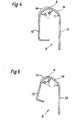
- the runners 9 in FIGS. 3 and 4 have a guide part which has a quarter curve 10 for the thread passage between the short leg 12 and the apex 8 and a straight to slightly curved section 14 between the apex 8 and the long leg 13.
- the radii of the rotor 9 advantageously have the following values:
- the runner 11 shown in FIG. 5 differs from the runner 9 by legs 12, 13 widening in a V-shape and other values for the radii, which are preferably assumed as follows: R 1 1,5 1.5 mm, R 2 0,8 0.8 mm and r ⁇ 1 mm.
- FIG. 6 shows a runner 15, measured in detail, as can be used for the Tex 20 number range.
- the mass of this rotor 15 corresponds to ISO standard No. 2266, series R20, No. 45 (ie 1,000 pieces weigh 45 grams).
- the two small radii r and R 2 1.2 mm for section 14 are clearly visible.
- the radius of the arc R 1 is significantly larger (1.6 mm).
Landscapes
- Engineering & Computer Science (AREA)
- Mechanical Engineering (AREA)
- Textile Engineering (AREA)
- Spinning Or Twisting Of Yarns (AREA)
Description
Die vorliegende Erfindung bezieht sich auf einen Läufer für Ringspinnmaschinen gemäss Oberbegriff des Patentanspruches 1. Aus dem DE-U-78 14 259 sind verschiedene Ausbildungen von Läufern für kegelförmige Spinnringe bekannt. Der dort beanspruchte Läufer weist einen aus zwei symmetrisch liegenden, in einem Winkel zusammenlaufenden geraden Teilstücken bestehenden Fadenführerteil auf. Mit dieser Ausbildung soll der Nachteil eines zu engen Durchganges für das Garn zwischen Ring und Läufer behoben werden, wie es beispielsweise in der DE-B-12 84 338 beschrieben wird.The present invention relates to a rotor for ring spinning machines according to the preamble of claim 1. From DE-U-78 14 259 various designs of rotor for conical spinning rings are known. The runner claimed there has a thread guide part consisting of two symmetrical lying straight sections converging at an angle. With this design, the disadvantage of too narrow a passage for the yarn between the ring and the rotor is to be eliminated, as is described, for example, in DE-B-12 84 338.
Tatsächlich ergibt sich bei dem aus geraden Teilstücken bestehenden Fadenführungsteil ein wesentlich grösserer Durchgangsquerschnitt zwischen Ring und Läufer als bei einem halbbogenförmigen Führungsteil. Allerdings wird durch diese Geometrie des Führungsteiles mit dem kleinen Radius der Fadenlauf genau definiert. Dies führt zu raschem Verschleiss des Läufers im Scheitelradius zwischen den geraden Teilstücken.In fact, the thread guide part consisting of straight sections results in a substantially larger passage cross section between the ring and the runner than in the case of a semi-arch-shaped guide part. However, this geometry of the guide part with the small radius precisely defines the thread path. This leads to rapid wear of the rotor in the apex radius between the straight sections.
Es kann auch nicht vermieden werden, dass sich im Radius Dickstellen und Ansetzer trotz grossem Durchgangsquerschnitt verklemmen und schlecht durchlaufen. Weiter neigt diese Läuferform dazu, Einzelfasern an der Garnoberfläche aufzuschieben, was zu haarigem Garn und zu Nissenbildung führen kann.It can also not be avoided that thick spots and attachments jam in the radius and run through poorly despite the large passage cross-section. Furthermore, this runner shape tends to push individual fibers onto the surface of the yarn, which can lead to hairy yarn and to the formation of nits.
Die Aufgabe der vorliegenden Erfindung besteht nun darin, einen Läufer zu schaffen, welcher einen genügend grossen Fadendurchgang aufweist und gute Fadenlaufeigenschaften hat, ohne dass die Masse und damit die Fliehkräfte gegenüber den bekannten Läufern zunehmen.The object of the present invention is to create a runner which has a sufficiently large thread passage and has good thread running properties without the mass and thus the centrifugal forces increasing compared to the known runners.
Eine weitere Aufgabe besteht darin, für Dickstellen und Ansetzer einen reibungsarmen Durchlauf zu gewähren.Another task is to ensure a low-friction run for thick spots and piecing.
Erfindungsgemäss werden diese Aufgaben gemäss dem Kennzeichen des Patentanspruches 1 gelöst.According to the invention, these objects are achieved in accordance with the characterizing part of patent claim 1.
Weitere vorteilhafte Ausführungsformen ergeben sich aus den Ansprüchen 2 und 3.Further advantageous embodiments result from claims 2 and 3.
Ueberraschenderweise werden die Nachteile der bekannten Läufer durch die vorgeschlagene neuartige Ausbildung des Führungsteiles behoben, ohne dass die guten Laufeigenschaften der bekannten Läufer auf dem Ring in irgendeiner Weise beeinträchtigt werden.Surprisingly, the disadvantages of the known runners are eliminated by the proposed novel design of the guide part, without the good running properties of the known runners on the ring being impaired in any way.
Der gerade Abschnitt des Führungsteiles gewährleistet eine grosse Durchgangsöffnung zwischen Läufer und Ring und das anschliessende Viertelsbogenstück bringt die für den Lauf des Garnes notwendige undefinierte Führungsfläche und damit keinen örtlichen Verschleiss.The straight section of the guide part ensures a large through opening between the runner and the ring, and the subsequent quarter-curve piece brings the undefined guide surface necessary for the running of the yarn and therefore no local wear.
Des weiteren werden durch den grossen Radius des Viertelsbogens keine Einzelfasern aufgeschoben und Ansetzer können nicht verklemmen. Insbesondere bei sehr feinen Garnen mit kleinem Ring und Läufer wirkt sich dies besonders vorteilhaft aus.Furthermore, the large radius of the quarter arch means that no individual fibers are pushed on and piecing cannot jam. This is particularly advantageous for very fine yarns with a small ring and runner.
Die Erfindung wird nun im folgenden anhand von Ausführungsbeispielen näher erläutert.The invention will now be explained in more detail below with the aid of exemplary embodiments.
Es zeigen :
- Figuren 1 und 2 ein Querschnittprofil durch einen Spinnring mit herkömmlichem Läufer,
- Figur 3 ein Querschnittprofil durch einen Spinnring mit einem Läufer gemäss der Erfindung,
- Figur 4 einen Läufer nach Figur 3, vergrössert dargestellt,
Figur 5 einen Läufer nach Figur 4, jedoch mit v-förmiger Anordnung der Schenkel, speziell für feine Garnnummern mit entsprechend kleinem Ringprofil und Läufer,- Figur 6 einen Läufer mit konkreter Vermassung.
- 1 and 2 show a cross-sectional profile through a spinning ring with a conventional rotor,
- FIG. 3 shows a cross-sectional profile through a spinning ring with a rotor according to the invention,
- FIG. 4 shows a rotor according to FIG. 3, enlarged,
- 5 shows a runner according to FIG. 4, but with a v-shaped arrangement of the legs, especially for fine thread numbers with a correspondingly small ring profile and runner,
- Figure 6 shows a runner with concrete dimensions.
Die in den Figuren 1 und 2 gezeigten, aus dem Stand der Technik bekannten Läufer 1 und 2 sind in Funktionsstellung auf einem Ring 3.dargestellt. Beim Läufer 1 mit halbbogenförmigem Führungsteil 4 ist deutlich der enge Durchgang für das Garn 5 zwischen dem Läufer 1 und der Oberkante des Ringes 3 ersichtlich (Fig. 1). Die Ausbildung des Führungsteiles des Läufers 2 aus zwei symmetrischen, in einem Winkel vorgesehenen geraden Abschnitten 6, 7 (Fig. 2) bringen ganz offensichtlich eine wesentliche Querschnittvergrösserung für den Garndurchgang. Allerdings läuft das Garn 5 immer genau im Scheitel 8 der beiden geraden Abschnitte 6, 7.The runners 1 and 2 shown in FIGS. 1 and 2 and known from the prior art are shown in the functional position on a ring 3. In the case of the runner 1 with the semicircular guide part 4, the narrow passage for the
Die Läufer 9 in Figur 3 und 4 haben einen Führungsteil, welcher zwischen dem kurzen Schenkel 12 und dem Scheitel 8 einen Viertelsbogen 10 für den Fadendurchlauf und zwischen dem Scheitel 8 und dem langen Schenkel 13 einen geraden bis leicht gebogenen Abschnitt 14 aufweist.The
Für Garn 5 mit Dickstellen ergibt sich ein grosser Durchgangsquerschnitt und gleichzeitig auf dem anschliessenden Bogenstück 10 die erwünschte breite, nicht definierte freie Gleitfläche. Die Radien des Läufers 9 weisen vorteilhafterweise folgende Werte auf :![]()
![]()
Der in Figur 5 dargestellte Läufer 11 unterscheidet sich vom Läufer 9 durch v-förmig sich erweiternde Schenkel 12, 13 sowie andere Werte für die Radien, welche vorzugsweise wie folgt angenommen werden : R1 ≥ 1,5 mm, R2 ≥ 0,8 mm und r ≥ 1 mm.The
Figur 6 zeigt einen detailliert vermassten Läufer 15, wie er für den Nummernbereich Tex 20 Anwendung finden kann. Dieser Läufer 15 entspricht in seiner Masse der ISO-Norm Nr. 2266, Serie R20, Nr. 45 (d. h. 1 000 Stück wiegen 45 Gramm) Klar ersichtlich sind die beiden kleinen Radien r und R2 = 1,2 mm beim Abschnitt 14. Der Radius des Bogens R1 ist bedeutend grösser (1,6 mm).FIG. 6 shows a
Claims (5)
Applications Claiming Priority (2)
| Application Number | Priority Date | Filing Date | Title |
|---|---|---|---|
| CH263/82 | 1982-01-18 | ||
| CH26382 | 1982-01-18 |
Publications (3)
| Publication Number | Publication Date |
|---|---|
| EP0084615A2 EP0084615A2 (en) | 1983-08-03 |
| EP0084615A3 EP0084615A3 (en) | 1984-01-11 |
| EP0084615B1 true EP0084615B1 (en) | 1986-07-30 |
Family
ID=4183019
Family Applications (1)
| Application Number | Title | Priority Date | Filing Date |
|---|---|---|---|
| EP82110299A Expired EP0084615B1 (en) | 1982-01-18 | 1982-11-09 | Traveller for a ring-spinning machine |
Country Status (3)
| Country | Link |
|---|---|
| US (1) | US4481764A (en) |
| EP (1) | EP0084615B1 (en) |
| DE (1) | DE3272364D1 (en) |
Families Citing this family (2)
| Publication number | Priority date | Publication date | Assignee | Title |
|---|---|---|---|---|
| EP0529227B1 (en) * | 1991-08-13 | 1994-12-14 | Bräcker AG | Traveller for an inclined flange ring |
| CH712733A1 (en) * | 2016-07-22 | 2018-01-31 | Bräcker Ag | Ring rotor. |
Family Cites Families (9)
| Publication number | Priority date | Publication date | Assignee | Title |
|---|---|---|---|---|
| US1880084A (en) * | 1931-12-10 | 1932-09-27 | U S Ring Traveler Company | Spinning or twisting device |
| GB422324A (en) * | 1933-06-19 | 1935-01-09 | Gaston Prosper Auguste Godefro | Improvements in and relating to travellers for continuous spinning and twisting frames |
| US2268772A (en) * | 1935-07-19 | 1942-01-06 | Victer Ring Traveler Company | Method of making ring travelers |
| FR980636A (en) * | 1949-02-11 | 1951-05-16 | Herr Mfg Company | Ring for spinning looms and its slider |
| US2831313A (en) * | 1955-01-10 | 1958-04-22 | Du Pont | Ring traveler |
| US3159963A (en) * | 1962-10-19 | 1964-12-08 | Zakharov Grigory Nickolajevich | Ring for spinning and twisting frames and traveller for the same |
| DE1284338B (en) * | 1962-10-19 | 1968-11-28 | Vnii Tekstilnogo I Ljogkogo Ma | Twisting device for spinning and twisting machines |
| DE2108225A1 (en) * | 1971-02-20 | 1972-08-31 | Chr. Mann, Maschinenfabrik, 7890 Waldshut | Ring runner for spinning or twisting machines - preventing vibration on ring and facilitating yarn insertion |
| GB1578552A (en) * | 1977-05-14 | 1980-11-05 | Eadie Bros & Co Ltd | Travellers for ring spinning machines |
-
1982
- 1982-11-09 DE DE8282110299T patent/DE3272364D1/en not_active Expired
- 1982-11-09 EP EP82110299A patent/EP0084615B1/en not_active Expired
-
1983
- 1983-01-10 US US06/457,000 patent/US4481764A/en not_active Expired - Lifetime
Also Published As
| Publication number | Publication date |
|---|---|
| EP0084615A3 (en) | 1984-01-11 |
| EP0084615A2 (en) | 1983-08-03 |
| US4481764A (en) | 1984-11-13 |
| DE3272364D1 (en) | 1986-09-04 |
Similar Documents
| Publication | Publication Date | Title |
|---|---|---|
| DE3333142A1 (en) | FUNNEL FOR SPINNING PREPARATION MACHINES, IN PARTICULAR LID CARDS, STRETCHES, COMBING MACHINES AND FLYERS | |
| EP0627561B1 (en) | Radial blorier | |
| EP0084615B1 (en) | Traveller for a ring-spinning machine | |
| EP0043868B1 (en) | Card clothing intended to be connected to the flat bars | |
| DE102005009213B4 (en) | Hydraulic vibration damper with kink-proof rebound stop spring | |
| CH680010A5 (en) | ||
| EP1382729B1 (en) | Latch needle | |
| EP0358015B1 (en) | Drawing frame with a pressing rod in the break draft zone | |
| DE3619356A1 (en) | EXTRACTION NOZZLE FOR PRE-TENSIONING AND SPINNING DEVICES | |
| DE4326205C1 (en) | Round comb | |
| DE10025191C2 (en) | Ring-traveler combination of a ring spinning or twisting machine | |
| EP1045052A3 (en) | Yarn guiding tube | |
| AT339133B (en) | SUCTION PLATE FOR PULP DEWATERING MACHINES, IN PARTICULAR PAPER MACHINES OR DGL. | |
| EP1255882A1 (en) | Fitting for a combing machine | |
| EP0686713B1 (en) | Pressfinger | |
| EP0489686B1 (en) | Nozzle for producing a swirl in an air jet spinning machine | |
| DE2038478A1 (en) | Textile felting needle - with double point | |
| DE19846883B4 (en) | sliver funnel | |
| DE19652913B4 (en) | Apparatus for simultaneously spinning and twisting two fiber strands into a false twist | |
| DE19819850C2 (en) | Spinning wing for a roving machine | |
| DE2641115B1 (en) | Paper web plastics forming screen dehydrating plate - with array of oppositely facing slots with sharp leading edges and rounded off trailing edges to assist suction effect | |
| AT386617B (en) | DEVICE FOR PRODUCING A YARN | |
| DE3103510C2 (en) | Device for pneumatic false twist spinning | |
| EP3744880A1 (en) | Swirl element for a spinneret of an air spinning machine and spinneret | |
| EP0369121A1 (en) | Heating method in textile machines |
Legal Events
| Date | Code | Title | Description |
|---|---|---|---|
| PUAI | Public reference made under article 153(3) epc to a published international application that has entered the european phase |
Free format text: ORIGINAL CODE: 0009012 |
|
| AK | Designated contracting states |
Designated state(s): CH DE FR GB IT LI |
|
| PUAL | Search report despatched |
Free format text: ORIGINAL CODE: 0009013 |
|
| AK | Designated contracting states |
Designated state(s): CH DE FR GB IT LI |
|
| 17P | Request for examination filed |
Effective date: 19840131 |
|
| GRAA | (expected) grant |
Free format text: ORIGINAL CODE: 0009210 |
|
| AK | Designated contracting states |
Kind code of ref document: B1 Designated state(s): CH DE FR GB IT LI |
|
| ET | Fr: translation filed | ||
| REF | Corresponds to: |
Ref document number: 3272364 Country of ref document: DE Date of ref document: 19860904 |
|
| ITF | It: translation for a ep patent filed |
Owner name: GUZZI E RAVIZZA S.R.L. |
|
| PLBE | No opposition filed within time limit |
Free format text: ORIGINAL CODE: 0009261 |
|
| STAA | Information on the status of an ep patent application or granted ep patent |
Free format text: STATUS: NO OPPOSITION FILED WITHIN TIME LIMIT |
|
| 26N | No opposition filed | ||
| ITTA | It: last paid annual fee | ||
| PGFP | Annual fee paid to national office [announced via postgrant information from national office to epo] |
Ref country code: GB Payment date: 19971024 Year of fee payment: 16 Ref country code: FR Payment date: 19971024 Year of fee payment: 16 |
|
| PGFP | Annual fee paid to national office [announced via postgrant information from national office to epo] |
Ref country code: DE Payment date: 19971028 Year of fee payment: 16 |
|
| PGFP | Annual fee paid to national office [announced via postgrant information from national office to epo] |
Ref country code: CH Payment date: 19971103 Year of fee payment: 16 |
|
| PG25 | Lapsed in a contracting state [announced via postgrant information from national office to epo] |
Ref country code: GB Free format text: LAPSE BECAUSE OF NON-PAYMENT OF DUE FEES Effective date: 19981109 |
|
| PG25 | Lapsed in a contracting state [announced via postgrant information from national office to epo] |
Ref country code: LI Free format text: LAPSE BECAUSE OF NON-PAYMENT OF DUE FEES Effective date: 19981130 Ref country code: CH Free format text: LAPSE BECAUSE OF NON-PAYMENT OF DUE FEES Effective date: 19981130 |
|
| GBPC | Gb: european patent ceased through non-payment of renewal fee |
Effective date: 19981109 |
|
| REG | Reference to a national code |
Ref country code: CH Ref legal event code: PL |
|
| PG25 | Lapsed in a contracting state [announced via postgrant information from national office to epo] |
Ref country code: FR Free format text: LAPSE BECAUSE OF NON-PAYMENT OF DUE FEES Effective date: 19990730 |
|
| REG | Reference to a national code |
Ref country code: FR Ref legal event code: ST |
|
| PG25 | Lapsed in a contracting state [announced via postgrant information from national office to epo] |
Ref country code: DE Free format text: LAPSE BECAUSE OF NON-PAYMENT OF DUE FEES Effective date: 19990901 |