EP0084577A1 - Method of and apparatus for heat transfer for the air conditioning of spaces for living beings in large numbers, in particular for livestock - Google Patents
Method of and apparatus for heat transfer for the air conditioning of spaces for living beings in large numbers, in particular for livestock Download PDFInfo
- Publication number
- EP0084577A1 EP0084577A1 EP82100413A EP82100413A EP0084577A1 EP 0084577 A1 EP0084577 A1 EP 0084577A1 EP 82100413 A EP82100413 A EP 82100413A EP 82100413 A EP82100413 A EP 82100413A EP 0084577 A1 EP0084577 A1 EP 0084577A1
- Authority
- EP
- European Patent Office
- Prior art keywords
- heat
- air
- amount
- fresh air
- rooms
- Prior art date
- Legal status (The legal status is an assumption and is not a legal conclusion. Google has not performed a legal analysis and makes no representation as to the accuracy of the status listed.)
- Granted
Links
- 238000000034 method Methods 0.000 title claims abstract description 13
- 238000004378 air conditioning Methods 0.000 title claims description 3
- 244000144972 livestock Species 0.000 title abstract 2
- 238000001816 cooling Methods 0.000 claims abstract description 20
- 230000005494 condensation Effects 0.000 claims abstract description 11
- 238000009833 condensation Methods 0.000 claims abstract description 11
- 238000010438 heat treatment Methods 0.000 claims abstract description 6
- 238000010521 absorption reaction Methods 0.000 claims abstract description 5
- 239000002826 coolant Substances 0.000 claims description 14
- XLYOFNOQVPJJNP-UHFFFAOYSA-N water Substances O XLYOFNOQVPJJNP-UHFFFAOYSA-N 0.000 claims description 6
- 239000006096 absorbing agent Substances 0.000 claims description 5
- 230000002745 absorbent Effects 0.000 claims 1
- 239000002250 absorbent Substances 0.000 claims 1
- 238000005057 refrigeration Methods 0.000 claims 1
- 238000001704 evaporation Methods 0.000 description 3
- 230000008020 evaporation Effects 0.000 description 3
- 238000003975 animal breeding Methods 0.000 description 2
- 239000000498 cooling water Substances 0.000 description 1
- 238000010586 diagram Methods 0.000 description 1
- 230000007704 transition Effects 0.000 description 1
- 238000009423 ventilation Methods 0.000 description 1
Images
Classifications
-
- A—HUMAN NECESSITIES
- A01—AGRICULTURE; FORESTRY; ANIMAL HUSBANDRY; HUNTING; TRAPPING; FISHING
- A01K—ANIMAL HUSBANDRY; AVICULTURE; APICULTURE; PISCICULTURE; FISHING; REARING OR BREEDING ANIMALS, NOT OTHERWISE PROVIDED FOR; NEW BREEDS OF ANIMALS
- A01K1/00—Housing animals; Equipment therefor
- A01K1/0047—Air-conditioning, e.g. ventilation, of animal housings
-
- F—MECHANICAL ENGINEERING; LIGHTING; HEATING; WEAPONS; BLASTING
- F24—HEATING; RANGES; VENTILATING
- F24D—DOMESTIC- OR SPACE-HEATING SYSTEMS, e.g. CENTRAL HEATING SYSTEMS; DOMESTIC HOT-WATER SUPPLY SYSTEMS; ELEMENTS OR COMPONENTS THEREFOR
- F24D5/00—Hot-air central heating systems; Exhaust gas central heating systems
- F24D5/12—Hot-air central heating systems; Exhaust gas central heating systems using heat pumps
-
- F—MECHANICAL ENGINEERING; LIGHTING; HEATING; WEAPONS; BLASTING
- F24—HEATING; RANGES; VENTILATING
- F24F—AIR-CONDITIONING; AIR-HUMIDIFICATION; VENTILATION; USE OF AIR CURRENTS FOR SCREENING
- F24F12/00—Use of energy recovery systems in air conditioning, ventilation or screening
- F24F12/001—Use of energy recovery systems in air conditioning, ventilation or screening with heat-exchange between supplied and exhausted air
- F24F12/002—Use of energy recovery systems in air conditioning, ventilation or screening with heat-exchange between supplied and exhausted air using an intermediate heat-transfer fluid
-
- F—MECHANICAL ENGINEERING; LIGHTING; HEATING; WEAPONS; BLASTING
- F24—HEATING; RANGES; VENTILATING
- F24F—AIR-CONDITIONING; AIR-HUMIDIFICATION; VENTILATION; USE OF AIR CURRENTS FOR SCREENING
- F24F3/00—Air-conditioning systems in which conditioned primary air is supplied from one or more central stations to distributing units in the rooms or spaces where it may receive secondary treatment; Apparatus specially designed for such systems
- F24F3/12—Air-conditioning systems in which conditioned primary air is supplied from one or more central stations to distributing units in the rooms or spaces where it may receive secondary treatment; Apparatus specially designed for such systems characterised by the treatment of the air otherwise than by heating and cooling
- F24F3/14—Air-conditioning systems in which conditioned primary air is supplied from one or more central stations to distributing units in the rooms or spaces where it may receive secondary treatment; Apparatus specially designed for such systems characterised by the treatment of the air otherwise than by heating and cooling by humidification; by dehumidification
- F24F3/1405—Air-conditioning systems in which conditioned primary air is supplied from one or more central stations to distributing units in the rooms or spaces where it may receive secondary treatment; Apparatus specially designed for such systems characterised by the treatment of the air otherwise than by heating and cooling by humidification; by dehumidification in which the humidity of the air is exclusively affected by contact with the evaporator of a closed-circuit cooling system or heat pump circuit
-
- F—MECHANICAL ENGINEERING; LIGHTING; HEATING; WEAPONS; BLASTING
- F25—REFRIGERATION OR COOLING; COMBINED HEATING AND REFRIGERATION SYSTEMS; HEAT PUMP SYSTEMS; MANUFACTURE OR STORAGE OF ICE; LIQUEFACTION SOLIDIFICATION OF GASES
- F25B—REFRIGERATION MACHINES, PLANTS OR SYSTEMS; COMBINED HEATING AND REFRIGERATION SYSTEMS; HEAT PUMP SYSTEMS
- F25B29/00—Combined heating and refrigeration systems, e.g. operating alternately or simultaneously
-
- Y—GENERAL TAGGING OF NEW TECHNOLOGICAL DEVELOPMENTS; GENERAL TAGGING OF CROSS-SECTIONAL TECHNOLOGIES SPANNING OVER SEVERAL SECTIONS OF THE IPC; TECHNICAL SUBJECTS COVERED BY FORMER USPC CROSS-REFERENCE ART COLLECTIONS [XRACs] AND DIGESTS
- Y02—TECHNOLOGIES OR APPLICATIONS FOR MITIGATION OR ADAPTATION AGAINST CLIMATE CHANGE
- Y02A—TECHNOLOGIES FOR ADAPTATION TO CLIMATE CHANGE
- Y02A40/00—Adaptation technologies in agriculture, forestry, livestock or agroalimentary production
- Y02A40/70—Adaptation technologies in agriculture, forestry, livestock or agroalimentary production in livestock or poultry
- Y02A40/76—Adaptation technologies in agriculture, forestry, livestock or agroalimentary production in livestock or poultry using renewable energy
-
- Y—GENERAL TAGGING OF NEW TECHNOLOGICAL DEVELOPMENTS; GENERAL TAGGING OF CROSS-SECTIONAL TECHNOLOGIES SPANNING OVER SEVERAL SECTIONS OF THE IPC; TECHNICAL SUBJECTS COVERED BY FORMER USPC CROSS-REFERENCE ART COLLECTIONS [XRACs] AND DIGESTS
- Y02—TECHNOLOGIES OR APPLICATIONS FOR MITIGATION OR ADAPTATION AGAINST CLIMATE CHANGE
- Y02B—CLIMATE CHANGE MITIGATION TECHNOLOGIES RELATED TO BUILDINGS, e.g. HOUSING, HOUSE APPLIANCES OR RELATED END-USER APPLICATIONS
- Y02B30/00—Energy efficient heating, ventilation or air conditioning [HVAC]
- Y02B30/13—Hot air central heating systems using heat pumps
-
- Y—GENERAL TAGGING OF NEW TECHNOLOGICAL DEVELOPMENTS; GENERAL TAGGING OF CROSS-SECTIONAL TECHNOLOGIES SPANNING OVER SEVERAL SECTIONS OF THE IPC; TECHNICAL SUBJECTS COVERED BY FORMER USPC CROSS-REFERENCE ART COLLECTIONS [XRACs] AND DIGESTS
- Y02—TECHNOLOGIES OR APPLICATIONS FOR MITIGATION OR ADAPTATION AGAINST CLIMATE CHANGE
- Y02B—CLIMATE CHANGE MITIGATION TECHNOLOGIES RELATED TO BUILDINGS, e.g. HOUSING, HOUSE APPLIANCES OR RELATED END-USER APPLICATIONS
- Y02B30/00—Energy efficient heating, ventilation or air conditioning [HVAC]
- Y02B30/56—Heat recovery units
-
- Y—GENERAL TAGGING OF NEW TECHNOLOGICAL DEVELOPMENTS; GENERAL TAGGING OF CROSS-SECTIONAL TECHNOLOGIES SPANNING OVER SEVERAL SECTIONS OF THE IPC; TECHNICAL SUBJECTS COVERED BY FORMER USPC CROSS-REFERENCE ART COLLECTIONS [XRACs] AND DIGESTS
- Y02—TECHNOLOGIES OR APPLICATIONS FOR MITIGATION OR ADAPTATION AGAINST CLIMATE CHANGE
- Y02P—CLIMATE CHANGE MITIGATION TECHNOLOGIES IN THE PRODUCTION OR PROCESSING OF GOODS
- Y02P60/00—Technologies relating to agriculture, livestock or agroalimentary industries
- Y02P60/12—Technologies relating to agriculture, livestock or agroalimentary industries using renewable energies, e.g. solar water pumping
-
- Y—GENERAL TAGGING OF NEW TECHNOLOGICAL DEVELOPMENTS; GENERAL TAGGING OF CROSS-SECTIONAL TECHNOLOGIES SPANNING OVER SEVERAL SECTIONS OF THE IPC; TECHNICAL SUBJECTS COVERED BY FORMER USPC CROSS-REFERENCE ART COLLECTIONS [XRACs] AND DIGESTS
- Y02—TECHNOLOGIES OR APPLICATIONS FOR MITIGATION OR ADAPTATION AGAINST CLIMATE CHANGE
- Y02P—CLIMATE CHANGE MITIGATION TECHNOLOGIES IN THE PRODUCTION OR PROCESSING OF GOODS
- Y02P60/00—Technologies relating to agriculture, livestock or agroalimentary industries
- Y02P60/50—Livestock or poultry management
Definitions
- the invention relates to a method for heat transfer for air conditioning rooms for living things large numbers, especially for animal husbandry, wherein the used air is removed and fresh air is introduced for it and the vapors produced by the living beings are condensed below their dew point.
- Plants are known (see e.g. HU-PS 174.791) in which the greater part of the amount of vapors produced in animal breeding rooms is not dissipated by ventilation, but by vapor condensation and the heat thus obtained is used in winter for room heating and in summer for room cooling.
- the heat that can be obtained by vapor condensation the temperature of which is low, only the cold fresh air can be preheated from the outside, but not the loss of heat transfer in the room.
- the cooling system can only use a small proportion of the heat obtained by vapor condensation in summer, and therefore the achievable economic effectiveness is not sufficient.
- the invention is based on the knowledge that when the amount of heat obtained by vapor condensation is increased from its low source temperature by switching on a heat pump to a higher temperature, the ge the amount of heat gained can be used much more economically in winter to heat the fresh air or air in the room and in summer to start up the cooling system with thermal energy.
- the essence of the method according to the invention is that the temperature of the amount of heat released by condensation increases to a temperature higher than the room temperature in a manner known per se and the portion of the amount of heat released by the condensation that is not released to the environment is conducted into the heat-absorbing medium and in itself is used in a known manner.
- the essence of the device according to the invention is that its heat absorber is a heat pump, preferably an evaporator of the cooling circuit with a compressor, and that a heat emitter, preferably a condenser, is arranged in the cooling circuit.
- a heat pump preferably an evaporator of the cooling circuit with a compressor
- a heat emitter preferably a condenser
- the fan 2 preferably has a variable speed in order to make the supply of the room 1 with fresh air adaptable to the change in the number of living beings held therein.
- the fresh air is preheated in the winter by means of a treatment system 4, and is introduced into the room 1 cooled in the summer through the air line 3.
- the heat-absorbing surface of the cooling circuit 5 with blower forms the surface for vapor condensation below the dew point, which is preferably an evaporator 6.
- the compressor 7 arranged in the cooling circuit 5 increases the temperature of the amount of heat obtained by the condensation to a higher value, and this higher amount of heat is emitted by a heat emitter also arranged in the cooling circuit 5, preferably through a condenser 8, to the heat-absorbing medium, which is preferably water is.
- the water heats up by absorbing the amount of heat and is introduced through a control valve, preferably through a two-way valve 9, partly into an air heater 10 suitable for indirect heating of the room 1, and partly through a preheater 11 of the treatment system 4 for preheating the fresh air.
- the flow through the heat-absorbing and heat-emitting media and the cooling circuit are closed by the throttle valve.
- the amount of heat dissipated by the cooling circuit 5 is fed to a boiler 14 of an absorption cooling system 13 and preheats a solution with a high coolant content by means of a heat exchanger 15. If necessary, a further heat removal from the absorbed coolant is carried out by a second heat exchanger 16 by means of supplied energy.
- the cooling medium guided by the removal of heat is condensed in an evaporation condenser 17, preferably from the evaporation system, and introduced through a throttle valve 18 into an evaporator 19 of the water cooler.
- the evaporated cooling medium is sucked in by an absorber, absorbs the low-coolant solution, and so on Tested solution with high coolant content is returned from a pump 20 for coolant solution through a heat exchanger 21 for solutions with high and low coolant content into the heat exchanger 15, where the process begins again.
- a heat exchanger 23 in an absorber 22 between the evaporator 19 of the water cooler and the pump 20 for coolant solution serves to remove the heat of the solution.
- the cooling circuit 5 takes only the amount of heat that is necessary to remove the vapors formed. If this amount of heat is used neither for heating nor for cooling, the cooling water of the condenser 8 is fed to the evaporation condenser 17, which now works as a water recooler.
- the evaporator 6 and the air heater 10 are arranged in a common air circulation unit 25 with an air blower 24.
- the used air is discharged from the room 1 through a discharge opening 26.
- a heat exchanger 27 for effectiveness Arranged in front of the discharge opening 26 is a heat exchanger 27 for effectiveness, which is practically one which is connected to a heat exchanger 28 arranged in the treatment system 4 for fresh air.
- the amount of heat absorbed by the heat exchanger 27 for the purpose of effectiveness can thus improve the efficiency of the preheating of the fresh air introduced.
Landscapes
- Engineering & Computer Science (AREA)
- Mechanical Engineering (AREA)
- General Engineering & Computer Science (AREA)
- Chemical & Material Sciences (AREA)
- Combustion & Propulsion (AREA)
- Life Sciences & Earth Sciences (AREA)
- Thermal Sciences (AREA)
- Physics & Mathematics (AREA)
- Environmental Sciences (AREA)
- Zoology (AREA)
- Animal Husbandry (AREA)
- Biodiversity & Conservation Biology (AREA)
- Sorption Type Refrigeration Machines (AREA)
- Organic Low-Molecular-Weight Compounds And Preparation Thereof (AREA)
- Central Air Conditioning (AREA)
Abstract
Description
Die Erfindung bezieht sich auf ein Verfahren für die Wärmeübertragung zur Luftkonditionierung von Räumen für Lebewesen großer Zahl, besonders für die Tierhaltung, wobei die verbrauchte Luft abgeführt und dafür Frischluft eingeführt wird und die durch die Lebewesen erzeugten Brüden unter ihren Taupunkt kondensiert werden.The invention relates to a method for heat transfer for air conditioning rooms for living things large numbers, especially for animal husbandry, wherein the used air is removed and fresh air is introduced for it and the vapors produced by the living beings are condensed below their dew point.
Bekannt sind Anlagen (vgl. z.B. die HU-PS 174.791) bei denen der größere Anteil der in Tierzuchträumen erzeugten Brüdenmenge nicht durch Ventilation, sondern durch Brüdenkondensation abgeführt wird und die so gewonnene Wärme im Winter zur Raumheizung, im Sommer zur Raumkühlung benutzt wird. Mit der durch Brüdenkondensation gewinnbaren Wärme, deren Temperatur niedrig ist, läßt sich nur die kalte Frischluft von Außen vorerwärmen, jedoch nicht der Wärmeübertragungsverlust im Raum ergänzen. Die Kühlanlage kann im Sommer nur einen geringen Anteil der durch Brüdenkondensation gewonnenen Wärme benutzen, und daher ist die erzielbare wirtschaftliche Wirksamkeit nicht ausreichend.Plants are known (see e.g. HU-PS 174.791) in which the greater part of the amount of vapors produced in animal breeding rooms is not dissipated by ventilation, but by vapor condensation and the heat thus obtained is used in winter for room heating and in summer for room cooling. With the heat that can be obtained by vapor condensation, the temperature of which is low, only the cold fresh air can be preheated from the outside, but not the loss of heat transfer in the room. The cooling system can only use a small proportion of the heat obtained by vapor condensation in summer, and therefore the achievable economic effectiveness is not sufficient.
Der Erfindung liegt die Erkenntnis zugrunde, daß, wenn die durch Brüdenkondensation gewonnene Wärmemenge von ihrer niedrigen Entstehungstemperatur durch Einschaltung einer Wärmepumpe auf höhere Temperatur erhöht wird, sich die gewonnene Wärmemenge viel wirtschaftlicher im Winter zur Erwärmung der Frischluft bzw. der Luft im Raum und im Sommer zur Inbetriebhaltung der Kühlanlage mit Wärmeenergie verwenden läßt.The invention is based on the knowledge that when the amount of heat obtained by vapor condensation is increased from its low source temperature by switching on a heat pump to a higher temperature, the ge the amount of heat gained can be used much more economically in winter to heat the fresh air or air in the room and in summer to start up the cooling system with thermal energy.
Das entsprechende erfindungsgemäße Verfahren und die zugehörige Vorrichtung gehen aus den Ansprüchen hervor.The corresponding method according to the invention and the associated device emerge from the claims.
Das Wesen des erfindungsgemäßen Verfahrens liegt darin, daß die Temperatur der durch Kondensation freigemachten Wärmemenge auf eine höhere Temperatur als die Raumtemperatur auf ansich bekannte Weise erhöht und der an die Umgebung nicht abgegebene Anteil der durch die Kondensation freigemachten Wärmemenge in das wärmeaufnehmende Medium geführt und in ansich bekannter Weise genutzt wird.The essence of the method according to the invention is that the temperature of the amount of heat released by condensation increases to a temperature higher than the room temperature in a manner known per se and the portion of the amount of heat released by the condensation that is not released to the environment is conducted into the heat-absorbing medium and in itself is used in a known manner.
Das Wesen der erfindungsgemäßen Vorrichtung liegt darin, daß ihr Wärmeaufnehmer eine Wärmepumpe, vorzugsweise ein Evaporator des Kühlkreises mit Kompressor ist, und daß im Kühlkreis ein Wärmeabgeber, vorzugsweise ein Kondensator, angeordnet ist.The essence of the device according to the invention is that its heat absorber is a heat pump, preferably an evaporator of the cooling circuit with a compressor, and that a heat emitter, preferably a condenser, is arranged in the cooling circuit.
Die erfindungsgemäße Vorrichtung ist im folgenden anhand eines Ausführungsbeispieles und der Zeichnung näher erläutert.The device according to the invention is explained in more detail below using an exemplary embodiment and the drawing.
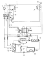
Die einzige Figur der Zeichnung zeigt ein Ausführungsbeispiel für das Schaltschema einer erfindungsgemäßen Vorrichtung.The only figure of the drawing shows an embodiment for the circuit diagram of a device according to the invention.
Ein Raum 1 mit Lebewesen großer Zahl, vorzugsweise für Tierzucht, wird mittels eines Gebläses 2 durch eine Luftleitung 3 mit Frischluft versorgt. Das Gebläse 2 hat vorzugsweise eine veränderliche Drehzahl, um die Versorgung des Raumes 1 mit Frischluft der Änderung der Zahl der darin gehaltenen Lebewesen anpaßbar zu machen.A
Die Frischluft wird im Winter mittels eines Behandlungssystems 4 vorgewärmt, im Sommer gekühlt durch die Luftleitung 3 in den Raum 1 eingeführt.The fresh air is preheated in the winter by means of a
Die wärmeaufnehmende Oberfläche des Kühlkreises 5 mit Gebläse bildet die Oberfläche zur Brüdenkondensation unter dem Taupunkt, die vorzugsweise ein Evaporator 6 ist. Der im Kühlkreis 5 angeordnete Kompressor 7 erhöht die Temperatur der durch die Kondensation gewonnenen Wärmemenge auf einen höheren Wert, und diese Wärmemenge höherer Temperatur wird durch einen ebenfalls im Kühlkreis 5 angeordneten Wärmeabgeber, vorzugsweise durch einen Kondensator 8 an das wärmeaufnehmende Medium abgegeben, welches vorzugsweise Wasser ist. Das Wasser erwärmt sich durch die Aufnahme der Wärmemenge und wird durch ein Regelventil, vorzugsweise durch ein Zweiwegventil 9, teils in einen für die mittelbare Heizung des Raumes 1 geeigneten Lufterwärmer 10 eingeführt, teils durch einen Vorerwärmer 11 des Behandlungssystems 4 zum Vorerwärmen der Frischluft benutzt. Das Durchströmen der wärmeaufnehmenden und wärmeabgebenden Medien und der Kühlumlauf werden vom Drosselventil geschlossen.The heat-absorbing surface of the
Im Sommer, wenn keine Heizung benötigt wird, sondern vielmehr die Luft eher zu kühlen ist, wird die durch den Kühlkreis 5 abgeführte Wärmemenge einem Kessel 14 eines Absorptionskühlsystems 13 zugeführt, und sie wärmt eine Lösung mit hohem Kühlmittelinhalt durch einen Wärmetauscher 15 vor. Falls notwendig, wird eine weitere Wärmeentnahme aus dem absorbierten Kühlmittel durch einen zweiten Wärmetauscher 16 mittels zugeführter Energie durchgeführt. Das durch die Wärmeentnahme geführte Kühlmedium wird in einem Evaporationskondensator 17, vorzugsweise vom Evaporationssystem, kondensiert und durch ein Drosselventil 18 in einen Evaporator 19 des Wasserkühlers eingeleitet. Das evaporierte Kühlmedium wird von einem Absorber angesaugt, absorbiert die Lösung mit geringem Kühlmittelinhalt, und die so erzeugte Lösung mit hohem Kühlmittelinhalt wird von einer Pumpe 20 für Kühlmittellösung durch einen Wärmetauscher 21 für Lösungen mit hohem und geringem Kühlmittelinhalt in den Wärmetauscher 15 zurückgeführt, wo das Verfahren von neuem beginnt. Ein Wärmetauscher 23 in einem Absorber 22 zwischen dem Evaporator 19 des Wasserkühlers und der Pumpe 20 für Kühlmittellösung dient zur Entnahme der Lösungswärme.In summer, when no heating is required, but rather the air is rather to be cooled, the amount of heat dissipated by the
Ist nur ein geringer Bedarf an Wärme vorhanden, z.B. während der Ubergangsjahreszeit, so entnimmt der Kühlkreis 5 nur die Wärmemenge, die zur Abführung der entstandenen Brüde notwendig ist. Wird diese Wärmemenge weder zur Heizung noch zur Kühlung benutzt, so wird das Kühlwasser des Kondensators 8 dem Evaporationskondensator 17 zugeführt, der nun als Wasserrückkühler arbeitet.Is there little need for heat, e.g. during the transition season, the
Der Evaporator 6 und der Lufterwärmer 10 sind bei einer der bevorzugten Ausführungen in einer gemeinsamem Luftumlaufeinheit 25 mit Luftgebläse 24 angeordnet.In one of the preferred embodiments, the evaporator 6 and the
Die verbrauchte Luft wird durch eine Abgabeöffnung 26 aus dem Raum 1 abgeführt. Vor der Abgabeöffnung 26 ist ein Wärmetauscher 27 zur Effektivisierung angeordnet, der praktisch ein solcher ist, der mit einem in dem Behandlungssystem 4 für Frischluft angeordneten Wärmetauscher 28 verbunden ist. Die durch den Wärmetauscher 27 zur Effektivisierung aufgenommene Wärmemenge kann so den Wirkungsgrad der Vorerwärmung der eingeleiteten Frischluft verbessern.The used air is discharged from the
Claims (13)
Priority Applications (3)
| Application Number | Priority Date | Filing Date | Title |
|---|---|---|---|
| AT82100413T ATE38890T1 (en) | 1982-01-21 | 1982-01-21 | METHOD AND DEVICE FOR HEAT TRANSFER FOR AIR CONDITIONING OF SPACES FOR LARGE NUMBERS OF LIVING BEINGS, ESPECIALLY FOR ANIMAL HUSBANDRY. |
| EP82100413A EP0084577B1 (en) | 1982-01-21 | 1982-01-21 | Method of and apparatus for heat transfer for the air conditioning of spaces for living beings in large numbers, in particular for livestock |
| DE8282100413T DE3279230D1 (en) | 1982-01-21 | 1982-01-21 | Method of and apparatus for heat transfer for the air conditioning of spaces for living beings in large numbers, in particular for livestock |
Applications Claiming Priority (1)
| Application Number | Priority Date | Filing Date | Title |
|---|---|---|---|
| EP82100413A EP0084577B1 (en) | 1982-01-21 | 1982-01-21 | Method of and apparatus for heat transfer for the air conditioning of spaces for living beings in large numbers, in particular for livestock |
Publications (2)
| Publication Number | Publication Date |
|---|---|
| EP0084577A1 true EP0084577A1 (en) | 1983-08-03 |
| EP0084577B1 EP0084577B1 (en) | 1988-11-23 |
Family
ID=8188833
Family Applications (1)
| Application Number | Title | Priority Date | Filing Date |
|---|---|---|---|
| EP82100413A Expired EP0084577B1 (en) | 1982-01-21 | 1982-01-21 | Method of and apparatus for heat transfer for the air conditioning of spaces for living beings in large numbers, in particular for livestock |
Country Status (3)
| Country | Link |
|---|---|
| EP (1) | EP0084577B1 (en) |
| AT (1) | ATE38890T1 (en) |
| DE (1) | DE3279230D1 (en) |
Cited By (2)
| Publication number | Priority date | Publication date | Assignee | Title |
|---|---|---|---|---|
| FR3011913A1 (en) * | 2013-10-16 | 2015-04-17 | Muller & Cie Soc | THERMAL REGULATION INSTALLATION OF A BUILDING |
| CN106765612A (en) * | 2017-02-17 | 2017-05-31 | 安徽理工大学 | A kind of energy-saving type air conditioner plumbing installation |
Citations (4)
| Publication number | Priority date | Publication date | Assignee | Title |
|---|---|---|---|---|
| FR1278089A (en) * | 1960-10-26 | 1961-12-08 | Bonnet Ets | Improvements to air conditioning installations |
| DE2509038B2 (en) * | 1975-03-01 | 1978-09-07 | Planungsbuero Obermeyer, Gesellschaft Fuer Planungen Im Bauwesen Mbh, 8000 Muenchen | Device for conditioning room air |
| DE2710125A1 (en) * | 1977-03-09 | 1978-09-14 | Heinrich H Esch | Stable air cleaning and ventilation system - extracts stale air, cools it and removes condensate for adding to dung pit |
| WO1980000486A1 (en) * | 1978-08-15 | 1980-03-20 | Vaestsvensk En Teknik Kb | A system for maintaining suitable air conditions in animal stables,and for recovering by-products |
-
1982
- 1982-01-21 EP EP82100413A patent/EP0084577B1/en not_active Expired
- 1982-01-21 DE DE8282100413T patent/DE3279230D1/en not_active Expired
- 1982-01-21 AT AT82100413T patent/ATE38890T1/en active
Patent Citations (4)
| Publication number | Priority date | Publication date | Assignee | Title |
|---|---|---|---|---|
| FR1278089A (en) * | 1960-10-26 | 1961-12-08 | Bonnet Ets | Improvements to air conditioning installations |
| DE2509038B2 (en) * | 1975-03-01 | 1978-09-07 | Planungsbuero Obermeyer, Gesellschaft Fuer Planungen Im Bauwesen Mbh, 8000 Muenchen | Device for conditioning room air |
| DE2710125A1 (en) * | 1977-03-09 | 1978-09-14 | Heinrich H Esch | Stable air cleaning and ventilation system - extracts stale air, cools it and removes condensate for adding to dung pit |
| WO1980000486A1 (en) * | 1978-08-15 | 1980-03-20 | Vaestsvensk En Teknik Kb | A system for maintaining suitable air conditions in animal stables,and for recovering by-products |
Cited By (3)
| Publication number | Priority date | Publication date | Assignee | Title |
|---|---|---|---|---|
| FR3011913A1 (en) * | 2013-10-16 | 2015-04-17 | Muller & Cie Soc | THERMAL REGULATION INSTALLATION OF A BUILDING |
| EP2863130A1 (en) * | 2013-10-16 | 2015-04-22 | Société Muller & Cie | System for the thermal regulation of a building |
| CN106765612A (en) * | 2017-02-17 | 2017-05-31 | 安徽理工大学 | A kind of energy-saving type air conditioner plumbing installation |
Also Published As
| Publication number | Publication date |
|---|---|
| ATE38890T1 (en) | 1988-12-15 |
| EP0084577B1 (en) | 1988-11-23 |
| DE3279230D1 (en) | 1988-12-29 |
Similar Documents
| Publication | Publication Date | Title |
|---|---|---|
| DE3610332C2 (en) | ||
| DE2919655A1 (en) | SYSTEM AND METHOD FOR AIR CONDITIONING WITH LIQUID ABSORPTION | |
| DE3637700A1 (en) | METHOD FOR REGENERATING A DRYING CARTRIDGE LOADED WITH MOISTURE AND DEVICE FOR CARRYING OUT SUCH A METHOD | |
| DE1940052B2 (en) | AIR-COOLED PARTITION HEAT EXCHANGER | |
| EP0887606B1 (en) | Drying apparatus | |
| EP0084577A1 (en) | Method of and apparatus for heat transfer for the air conditioning of spaces for living beings in large numbers, in particular for livestock | |
| DE3201747A1 (en) | Method and device for heat transmission for air-conditioning rooms for living creatures in large numbers, in particular for animal keeping | |
| DE3629398A1 (en) | METHOD AND DEVICE FOR DEHUMIDIFYING GASEOUS MEDIA | |
| DE3036150C2 (en) | ||
| DE2846728A1 (en) | Heating and refrigerating system with gas absorber - utilises heat released on evaporation and refrigerates on condensation | |
| DE2802907A1 (en) | Malt kiln air conditioning system - uses glass tube heat exchanger in series with evaporator of heat pump for heat recuperation | |
| CH273897A (en) | Process for utilizing the heat generation of animals in a stable as well as system for the implementation of this process. | |
| DE4215898A1 (en) | Handling liquid in cooler closed prim. circuit including heat exchanger - flowing low temp. medium drawn by heat of ambient air and with increasing temp. of air, air stream drawn past heat exchanger is damped and sprayed by liquid | |
| DE507135C (en) | Fridge with a chiller | |
| WO1985005436A1 (en) | Energy saving system for the heating and/or cooling of installations, particularly animal breeding installations, comprised of rooms intended to be used as living place for a plurality of living beings | |
| DE3310382C1 (en) | Greenhouse, in which a number of mutually independent, table-like cultivation beds are arranged, which are insulated in relation to the interior of the greenhouse | |
| DE2441855A1 (en) | Installation for air drying wood - has circulation and off take fans and sensor control for operation of fans | |
| DE29804215U1 (en) | Drying plant, especially for sawn timber | |
| DD202067A5 (en) | METHOD AND DEVICE FOR TRANSFERRING WEIGHT FOR AIR CONDITIONING IN ROOMS FOR A LARGE NUMBER OF LIVING | |
| DE1454639A1 (en) | Process for air conditioning and air conditioning, in particular for vehicles | |
| DE549945C (en) | Condensation steam power plant with recooling device for the condensation cooling water | |
| DE2240122A1 (en) | VENTILATION UNIT FOR IN PARTICULAR SWIMMING POOLS | |
| DE1919290B2 (en) | Room air dehumidification system - uses additional condenser unit, switched in parallel with main unit via changeover valves | |
| DE3516054A1 (en) | Process and plant for purifying flue gases | |
| DE521667C (en) | Greenhouse plant |
Legal Events
| Date | Code | Title | Description |
|---|---|---|---|
| PUAI | Public reference made under article 153(3) epc to a published international application that has entered the european phase |
Free format text: ORIGINAL CODE: 0009012 |
|
| AK | Designated contracting states |
Designated state(s): AT BE CH DE FR GB IT LI LU NL SE |
|
| 17P | Request for examination filed |
Effective date: 19840125 |
|
| RAP1 | Party data changed (applicant data changed or rights of an application transferred) |
Owner name: KOEZPONTI VALTO-ES HITELBANK RT INNOVACIOS ALAP |
|
| GRAA | (expected) grant |
Free format text: ORIGINAL CODE: 0009210 |
|
| AK | Designated contracting states |
Kind code of ref document: B1 Designated state(s): AT BE CH DE FR GB IT LI LU NL SE |
|
| PG25 | Lapsed in a contracting state [announced via postgrant information from national office to epo] |
Ref country code: SE Effective date: 19881123 Ref country code: NL Effective date: 19881123 Ref country code: IT Free format text: LAPSE BECAUSE OF FAILURE TO SUBMIT A TRANSLATION OF THE DESCRIPTION OR TO PAY THE FEE WITHIN THE PRESCRIBED TIME-LIMIT;WARNING: LAPSES OF ITALIAN PATENTS WITH EFFECTIVE DATE BEFORE 2007 MAY HAVE OCCURRED AT ANY TIME BEFORE 2007. THE CORRECT EFFECTIVE DATE MAY BE DIFFERENT FROM THE ONE RECORDED. Effective date: 19881123 Ref country code: GB Free format text: LAPSE BECAUSE OF NON-PAYMENT OF DUE FEES Effective date: 19881123 Ref country code: FR Free format text: THE PATENT HAS BEEN ANNULLED BY A DECISION OF A NATIONAL AUTHORITY Effective date: 19881123 Ref country code: BE Effective date: 19881123 |
|
| REF | Corresponds to: |
Ref document number: 38890 Country of ref document: AT Date of ref document: 19881215 Kind code of ref document: T |
|
| REF | Corresponds to: |
Ref document number: 3279230 Country of ref document: DE Date of ref document: 19881229 |
|
| PG25 | Lapsed in a contracting state [announced via postgrant information from national office to epo] |
Ref country code: LU Free format text: LAPSE BECAUSE OF NON-PAYMENT OF DUE FEES Effective date: 19890131 Ref country code: LI Effective date: 19890131 Ref country code: CH Effective date: 19890131 |
|
| EN | Fr: translation not filed | ||
| NLV1 | Nl: lapsed or annulled due to failure to fulfill the requirements of art. 29p and 29m of the patents act | ||
| GBV | Gb: ep patent (uk) treated as always having been void in accordance with gb section 77(7)/1977 [no translation filed] | ||
| PLBE | No opposition filed within time limit |
Free format text: ORIGINAL CODE: 0009261 |
|
| STAA | Information on the status of an ep patent application or granted ep patent |
Free format text: STATUS: NO OPPOSITION FILED WITHIN TIME LIMIT |
|
| REG | Reference to a national code |
Ref country code: CH Ref legal event code: PL |
|
| 26N | No opposition filed | ||
| PGFP | Annual fee paid to national office [announced via postgrant information from national office to epo] |
Ref country code: AT Payment date: 19900122 Year of fee payment: 9 |
|
| PGFP | Annual fee paid to national office [announced via postgrant information from national office to epo] |
Ref country code: DE Payment date: 19900131 Year of fee payment: 9 |
|
| PG25 | Lapsed in a contracting state [announced via postgrant information from national office to epo] |
Ref country code: AT Effective date: 19910121 |
|
| PG25 | Lapsed in a contracting state [announced via postgrant information from national office to epo] |
Ref country code: DE Effective date: 19911001 |