EP0084520B1 - Filter system - Google Patents
Filter system Download PDFInfo
- Publication number
- EP0084520B1 EP0084520B1 EP19830810012 EP83810012A EP0084520B1 EP 0084520 B1 EP0084520 B1 EP 0084520B1 EP 19830810012 EP19830810012 EP 19830810012 EP 83810012 A EP83810012 A EP 83810012A EP 0084520 B1 EP0084520 B1 EP 0084520B1
- Authority
- EP
- European Patent Office
- Prior art keywords
- filter
- liquid
- vessel
- valve
- vessels
- Prior art date
- Legal status (The legal status is an assumption and is not a legal conclusion. Google has not performed a legal analysis and makes no representation as to the accuracy of the status listed.)
- Expired
Links
- 239000007788 liquid Substances 0.000 claims description 50
- 238000001914 filtration Methods 0.000 claims description 17
- 239000007787 solid Substances 0.000 claims description 11
- 238000000034 method Methods 0.000 description 3
- 239000012530 fluid Substances 0.000 description 2
- 238000011085 pressure filtration Methods 0.000 description 2
- 238000005086 pumping Methods 0.000 description 2
- 238000011001 backwashing Methods 0.000 description 1
- 238000010586 diagram Methods 0.000 description 1
- 239000006185 dispersion Substances 0.000 description 1
- 239000002245 particle Substances 0.000 description 1
- 239000011343 solid material Substances 0.000 description 1
Images
Classifications
-
- B—PERFORMING OPERATIONS; TRANSPORTING
- B01—PHYSICAL OR CHEMICAL PROCESSES OR APPARATUS IN GENERAL
- B01D—SEPARATION
- B01D35/00—Filtering devices having features not specifically covered by groups B01D24/00 - B01D33/00, or for applications not specifically covered by groups B01D24/00 - B01D33/00; Auxiliary devices for filtration; Filter housing constructions
- B01D35/12—Devices for taking out of action one or more units of multi- unit filters, e.g. for regeneration
Definitions
- the present invention relates to a filtration system for removing suspended solids from a liquid.
- a pressure filtration system with two parallel filter vessels has now been found, in which the liquid can be drained from the filter vessel that is not in operation before the full filter bag or the cartridge is removed.
- the present invention relates to a pressure filtration system for removing suspended solids from a liquid, consisting of two enclosed filter vessels arranged in parallel, each containing either a removable filter bag or a removable cartridge, and in the circulation line of the liquid from a main storage vessel only by one filter vessel pumping pump are arranged, this being controlled by a valve system in the circulation line to the filter vessels, the liquid pressed through the filter vessel in operation being pumped via a check valve arranged in the outlet line of the respective vessel into a liquid reservoir vessel, the outlet of each vessel has a connecting piece to a pendulum valve, the outlet of which is connected via a check valve to the suction side of the pump, so that when pumping liquid through the one vessel, the pendulum valve against the flow the liquid is blocked through it, but is open on the other side so that liquid can be sucked in from the other vessel.
- the valve system in the liquid circulation line for controlling the liquid supply to the filter vessel preferably consists of an electrically controlled solenoid valve in the liquid supply line to each vessel. There may also be a pneumatically operated valve in the liquid supply line to each vessel.
- a pressure sensitive switch is preferably used to determine and indicate when a filter vessel is too full of solid to function well.
- Devices for actuating the valve system in the liquid circulation line are particularly preferably connected to the pressure-sensitive switch in order to shut off one vessel and allow the liquid to be pumped through the other vessel.
- devices are provided for switching off the pump and thus for stopping the circulation of liquid when the sacks or cartridges in both filter vessels are too full and the filter can no longer function well, i. H. if the sack or the cartridge in the next container has not been replaced.
- the check valves in the liquid outlet lines from the two filter vessels and the pendulum valve are preferably floating check valves.
- An air return valve against vacuum is preferably installed on each filter vessel. This serves to prevent a high vacuum from being created in a filter vessel when the liquid is drawn off.
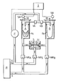
- the figure is a flow diagram, half in section, of a filtration system according to the invention.
- the filtration system is connected to a liquid reservoir R which contains suspended solids which have to be removed therefrom by means of an inlet pipe X and an outlet pipe Y.
- the filtration system consists of two pressure filter vessels A and B, each containing filter bags A 1 and Bi, and a liquid circulation pump P, which pumps the liquid from the reservoir R through the system, as indicated by the liquid flow arrows.
- two pressure-sensitive switches SA and SB are arranged, which are connected to an electronic control cabinet Z. These switches respond to pressure changes in vessels A and B; when the pressure reaches a predetermined level, one valve V A or V B is closed and the other is opened. Furthermore, two air check valves I A and I B are arranged at the head of each vessel. These valves act against vacuum.
- a pendulum valve S with a pendulum body S 1 is located in the liquid circuit under the two vessels A and B.
- Three floating check valves NR A , NR B and NRs are arranged in the liquid outlet lines of the vessels A and B or the shuttle valve S.
- the liquid to be filtered which is contained in the reservoir and contains a dispersion of solid particles is drawn in by pump P from reservoir R via inlet X.
- the liquid is then pumped through one or the other filter vessel A or B.
- the filter vessel used is selected by the corresponding states of the two valves V A and V B. In the figure, V A is in the open position and V B is closed.
- the suspended solids collect in the filter bag A.
- the filtered liquid is then pressed out of the filter vessel A and flows back to the reservoir R via the outlet Y.
- the pendulum body S 1 is under pressure on the left-hand side and represents a seal against the liquid flowing out of filter A.
- the check valve NR B prevents the pressurized liquid from flowing into the filter vessel B.
- any liquid present in the filter vessel B is sucked out via this route.
- the filter bag from A can easily be removed in a semi-dry state and a replacement filter can be used without interrupting the operation of the system.
- the filter vessels When the filter vessels are in the position shown in the figure, i. H. if fluid is pumped through vessel A but the fluid has been withdrawn from vessel B, a small amount of air is drawn from the pump through vessel B and shuttle valve S, but this can be minimized by the design of the flow system. If necessary, the pendulum body S can also be made to fit loosely into the pendulum channel, so that a small amount of liquid can flow from the vessel A into and out of the pendulum valve.
- the filtration system according to the invention is particularly useful when the filtered solids have to be recovered for further processing, since they are obtained in a semi-dry, compact state.
Description
Vorliegende Erfindung betrifft ein Filtriersystem zur Entfernung von suspendierten Feststoffen aus einer Flüssigkeit.The present invention relates to a filtration system for removing suspended solids from a liquid.
In vielen Fällen ist die Entfernung von suspendierten Feststoffen aus einer Flüssigkeit erforderlich, und dies geschieht häufig unter Verwendung eines Filtriersystems mit einem Filtersack oder einer Patrone in einem Filtergefäß. Wenn der Filtersack oder die Patrone mit dem herausfiltrierten Feststoff voll oder verstopft ist, so daß das Filtriersystem nicht mehr betriebsfähig ist, muß das System abgestellt und der Filtersack oder die Patrone ausgewechselt werden. Es ist jedoch oft lästig, die Filtration anhalten zu müssen, und deshalb werden manchmal zwei Filtergefäße parallel angeordnet, wobei das eine zum Filtrieren verwendet wird, während das andere zum Auswechseln des Sacks oder der Patrone geöffnet werden kann. Dies ist jedoch meist eine unsaubere Prozedur, da es schwierig ist, Flüssigkeit aus dem abgesperrten Filtergefäß abzulassen, insbesondere wenn wie üblich das Filtriersystem unter Druck steht.In many cases, suspended solids must be removed from a liquid, and this is often done using a filtration system with a filter bag or cartridge in a filter vessel. If the filter bag or the cartridge is full or clogged with the solid that has been filtered out, so that the filtration system is no longer operational, the system must be switched off and the filter bag or the cartridge replaced. However, it is often troublesome to have to stop filtration and therefore two filter vessels are sometimes arranged in parallel, one being used for filtering while the other can be opened to replace the sack or cartridge. However, this is usually an unclean procedure because it is difficult to drain liquid from the blocked filter vessel, especially when, as usual, the filtration system is under pressure.
Verschiedene Filtersysteme wurden beschrieben, in denen zwei Filter parallel angeordnet sind. Beispielsweise sind unterschiedliche, zwei parallel angeordnete Filter enthaltende Filtersysteme in den folgenden Patentschriften beschrieben: Britische Patentschriften Nr. 556 304, 1340726, 2014467 und 2 015 891, U.S. Patentschriften 2434427 und 3 979 292 sowie in der französischen Patentschrift 2 095 426. Jedoch wird bei keiner von diesen ein herausnehmbarer Filtersack oder eine herausnehmbare Patrone eingesetzt. Bei den meisten Patentschriften wird eine Rückspülmethode angewendet, um das nicht in Betrieb befindliche Filter zu reinigen. Solche Rückspülmethoden sind nicht anwendbar, wenn in einem Filtersystem ein herausnehmbares Filter oder eine herausnehmbare Patrone eingesetzt werden.Different filter systems have been described in which two filters are arranged in parallel. For example, different filter systems containing two filters arranged in parallel are described in the following patents: British Patent Nos. 556,304, 1340726, 2014467 and 2,015,891, U.S. Pat. Patents 2434427 and 3 979 292 and in French Patent 2 095 426. However, none of these uses a removable filter bag or cartridge. Most patents use a backwash method to clean the filter that is not in use. Such backwashing methods cannot be used if a removable filter or cartridge is used in a filter system.
Es wurde nun ein Druckfiltriersystem mit zwei parallelen Filtergefäßen gefunden, bei dem die Flüssigkeit aus dem nicht im Betrieb befindlichen Filtergefäß abgelassen werden kann, bevor der volle Filtersack bzw. die Patrone herausgenommen wird.A pressure filtration system with two parallel filter vessels has now been found, in which the liquid can be drained from the filter vessel that is not in operation before the full filter bag or the cartridge is removed.
Gegenstand vorliegender Erfindung ist ein Druckfiltriersystem zur Entfernung von suspendierten Feststoffen aus einer Flüssigkeit, bestehend aus zwei umschlossenen, parallel angeordneten Filtergefäßen, die je entweder einen herausnehmbaren Filtersack oder eine herausnehmbare Patrone enthalten und in der Umlaufleitung einer die Flüssigkeit aus einem Hauptvorratsgefäß jeweils nur durch ein Filtergefäß pumpenden Pumpe angeordnet sind, wobei dies durch ein Ventilsystem in der Umlaufleitung zu den Filtergefäßen gesteuert wird, wobei die durch das im Betrieb befindliche Filtergefäß gedrückte Flüssigkeit über ein in der Ausflußleitung des jeweiligen Gefäßes angeordnetes Rückschlagventil in ein Flüssigkeitsvorratsgefäß gepumpt wird, wobei der Auslaß jeden Gefäßes einen Verbindungsstutzen zu einem Pendelventil aufweist, dessen Auslaß über ein Rückschlagventil mit der Ansaugseite der Pumpe verbunden ist, wodurch beim Pumpen von Flüssigkeit durch das eine Gefäß das Pendelventil gegen die Strömung der Flüssigkeit durch dieses hindurch gesperrt, aber auf der anderen Seite offen ist, so daß Flüssigkeit aus dem anderen Gefäß angesaugt werden kann.The present invention relates to a pressure filtration system for removing suspended solids from a liquid, consisting of two enclosed filter vessels arranged in parallel, each containing either a removable filter bag or a removable cartridge, and in the circulation line of the liquid from a main storage vessel only by one filter vessel pumping pump are arranged, this being controlled by a valve system in the circulation line to the filter vessels, the liquid pressed through the filter vessel in operation being pumped via a check valve arranged in the outlet line of the respective vessel into a liquid reservoir vessel, the outlet of each vessel has a connecting piece to a pendulum valve, the outlet of which is connected via a check valve to the suction side of the pump, so that when pumping liquid through the one vessel, the pendulum valve against the flow the liquid is blocked through it, but is open on the other side so that liquid can be sucked in from the other vessel.
Vorzugsweise besteht das Ventilsystem in der Flüssigkeitsumlaufleitung zur Steuerung der Flüssigkeitszufuhr in das Filtergefäß aus einem elektrisch gesteuerten Magnetventil in der Flüssigkeitszufuhrleitung zu jedem Gefäß. Auch kann ein pneumatisch betätigtes Ventil in der Flüssigkeitszufuhrleitung zu jedem Gefäß vorhanden sein.The valve system in the liquid circulation line for controlling the liquid supply to the filter vessel preferably consists of an electrically controlled solenoid valve in the liquid supply line to each vessel. There may also be a pneumatically operated valve in the liquid supply line to each vessel.
Vorzugsweise dient ein druckempfindlicher Schalter dazu, festzustellen und anzuzeigen, wenn ein Filtergefäß zu voll mit Feststoff ist, um gut funktionieren zu können. Besonders bevorzugt sind Vorrichtungen zur Betätigung des Ventilsystems in der Flüssigkeitsumlaufleitung mit dem druckempfindlichen Schalter verbunden, um das eine Gefäß abzusperren und die Flüssigkeit durch das andere Gefäß gepumpt werden zu lassen.A pressure sensitive switch is preferably used to determine and indicate when a filter vessel is too full of solid to function well. Devices for actuating the valve system in the liquid circulation line are particularly preferably connected to the pressure-sensitive switch in order to shut off one vessel and allow the liquid to be pumped through the other vessel.
Bei einer Ausführungsform sind Vorrichtungen zum Abstellen der Pumpe und somit zum Anhalten des Flüssigkeitsumlaufs, wenn die Säkke oder Patronen in beiden Filtergefäßen zu voll sind und das Filter nicht mehr gut funktionieren kann, vorgesehen, d. h. wenn der Sack oder die Patrone im nächsten Gefäß nicht ausgewechselt worden ist.In one embodiment, devices are provided for switching off the pump and thus for stopping the circulation of liquid when the sacks or cartridges in both filter vessels are too full and the filter can no longer function well, i. H. if the sack or the cartridge in the next container has not been replaced.
Vorzugsweise sind die Rückschlagventile in den Flüssigkeitsauslaßleitungen aus den beiden Filtergefäßen und das Pendelventil Schwimmrückschlagventile.The check valves in the liquid outlet lines from the two filter vessels and the pendulum valve are preferably floating check valves.
Vorzugsweise ist an jedem Filtergefäß ein Luftrückstrahlventil gegen Vakuum abgebracht. Dies dient dazu, zu verhindern, daß in einem Filtergefäß beim Absaugen der Flüssigkeit ein hohes Vakuum entsteht.An air return valve against vacuum is preferably installed on each filter vessel. This serves to prevent a high vacuum from being created in a filter vessel when the liquid is drawn off.
Die Zeichnung dient der Erläuterung der Erfindung.The drawing serves to explain the invention.
Die Figur ist ein Fließbild, halb im Schnitt, eines erfindungsgemäßen Filtriersystems.The figure is a flow diagram, half in section, of a filtration system according to the invention.
In der Figur ist das Filtriersystem an ein Flüssigkeitsvorratsreservoir R angeschlossen, das suspendierte Feststoffe enthält, die daraus mittels eines Einlaßrohrs X und Auslaßrohrs Y entfernt werden müssen.In the figure, the filtration system is connected to a liquid reservoir R which contains suspended solids which have to be removed therefrom by means of an inlet pipe X and an outlet pipe Y.
Das Filtriersystem besteht aus zwei Druckfiltergefäßen A und B, die je Filtersäcke A1 und Bi enthalten, und einer Flüssigkeitsumlaufpumpe P, welche die Flüssigkeit aus dem Vorratsbehälter R durch das System pumpt, wie durch die Flüssigkeitsströmungspfeile angezeigt.The filtration system consists of two pressure filter vessels A and B, each containing filter bags A 1 and Bi, and a liquid circulation pump P, which pumps the liquid from the reservoir R through the system, as indicated by the liquid flow arrows.
In den Flüssigkeitszufuhrleitungen zu den Gefäßen A und B befinden sich zwei elektrisch gesteuerte Magnetventile VA und Vs. Nur eines dieser Ventile kann gleichzeitig offen sein.There are two electrically controlled solenoid valves V A and V s in the liquid supply lines to vessels A and B. Just one that This valve can be open at the same time.
Am Kopf der beiden Gefäße A und B sind je zwei druckempfindliche Schalter SA und SB angeordnet, die mit einem elektronischen Steuerschrank Z verbunden sind. Diese Schalter sprechen auf Druckänderungen in den Gefäßen A und B an; wenn der Druck eine vorgegebene Höhe erreicht, wird das eine Ventil VA bzw. VB geschlossen und das andere geöffnet. Ferner sind am Kopf jeden Gefäßes zwei Luftrückschlagventile IA und IB angeordnet. Diese Ventile wirken gegen Vakuum.At the head of the two vessels A and B, two pressure-sensitive switches SA and SB are arranged, which are connected to an electronic control cabinet Z. These switches respond to pressure changes in vessels A and B; when the pressure reaches a predetermined level, one valve V A or V B is closed and the other is opened. Furthermore, two air check valves I A and I B are arranged at the head of each vessel. These valves act against vacuum.
Im Flüssigkeitskreislauf unter den zwei Gefäßen A und B befindet sich ein Pendelventil S mit einem Pendelkörper S 1.A pendulum valve S with a pendulum body S 1 is located in the liquid circuit under the two vessels A and B.
Drei Schwimmrückschlagventile NRA, NRB und NRs sind in den Flüssigkeitsauslaßleitungen der Gefäße A und B bzw. des Pendelventils S angeordnet.Three floating check valves NR A , NR B and NRs are arranged in the liquid outlet lines of the vessels A and B or the shuttle valve S.
Im Betrieb wird die im Reservoir enthaltene und eine Dispersion fester Teilchen enthaltende, zu filtrierende Flüssigkeit durch die Pumpe P aus dem Reservoir R über den Einlaß X angesaugt.In operation, the liquid to be filtered which is contained in the reservoir and contains a dispersion of solid particles is drawn in by pump P from reservoir R via inlet X.
Die Flüssigkeit wird dann durch das eine oder andere Filtergefäß A oder B gepumpt. Die Wahl des verwendeten Filtergefäßes erfolgt durch die entsprechenden Zustände der beiden Ventile VA und VB. In der Figur ist VA in der offenen Stellung und VB ist geschlossen.The liquid is then pumped through one or the other filter vessel A or B. The filter vessel used is selected by the corresponding states of the two valves V A and V B. In the figure, V A is in the open position and V B is closed.
Die suspendierten Feststoffe sammeln sich in dem Filtersack A. Die filtrierte Flüssigkeit wird dann aus dem Filtergefäß A gedrückt und fließt über den Auslaß Y zum Reservoir R zurück.The suspended solids collect in the filter bag A. The filtered liquid is then pressed out of the filter vessel A and flows back to the reservoir R via the outlet Y.
In diesem Zustand steht der Pendelkörper S1 auf der linken Seite unter Druck und stellt eine Dichtung gegen die aus Filter A abströmende Flüssigkeit dar. Zusätzlich verhindert das Rückschlagventil NRB eine Strömung der unter Druck stehenden Flüssigkeit in das Filtergefäß B. Es besteht jedoch ein freier Weg vom Filtergefäß B durch die rechte Seite des Pendelventils S zurück zur Ansaugseite der Pumpe P. Somit wir gegebenenfalls im Filtergefäß B vorhandene Flüssigkeit über diesen Weg herausgesaugt.In this state, the pendulum body S 1 is under pressure on the left-hand side and represents a seal against the liquid flowing out of filter A. In addition, the check valve NR B prevents the pressurized liquid from flowing into the filter vessel B. However, there is a free one Away from the filter vessel B through the right side of the pendulum valve S back to the suction side of the pump P. Thus, any liquid present in the filter vessel B is sucked out via this route.
Wenn sich im Filtergefäß A eine erhebliche Menge festes Material angesammelt hat und der Flüssigkeitsdruck über dem Filtersack A auf eine vorgewählte Höhe gestiegen ist, wird dies von dem Druckschalter SA festgestellt, der über die Steuerelektronik das Ventil VA schließen und das Ventil VB öffnen läßt.If a substantial amount of solid material has accumulated in the filter vessel A and the liquid pressure above the filter bag A has risen to a preselected level, this is determined by the pressure switch S A , which closes the valve V A and opens the valve V B via the control electronics leaves.
Es ist ersichtlich, daß die oben beschriebene Flüssigkeitsströmung dabei so umgeändert wird, daß das Filtergefäß B nun zum Filtrieren der Flüssigkeit dient, während die Flüssigkeit automatisch über das Pendelventil S und die Pumpe aus dem Filtergefäß A abgezogen wird.It can be seen that the liquid flow described above is changed so that the filter vessel B now serves to filter the liquid, while the liquid is automatically drawn off from the filter vessel A via the shuttle valve S and the pump.
Der Filtersack aus A kann leicht in halbtrockenem Zustand herausgenommen und ein Ersatzfilter ohne Betriebsunterbrechung des Systems eingesetzt werden.The filter bag from A can easily be removed in a semi-dry state and a replacement filter can be used without interrupting the operation of the system.
Wenn die Filtergefäße sich in der in der Figur gezeigten Stellung befinden, d. h. wenn Flüssigkeit durch das Gefäß A gepumpt wird, aber die Flüssigkeit aus dem Gefäß B abgezogen wurde, wird eine geringe Menge Luft von der Pumpe durch das Gefäß B und das Pendelventil S gesaugt, aber dies kann durch die Auslegung des Strömungssystems minimiert werden. Wenn nötig, kann auch der Pendelkörper S lose in den Pendelkanal passend gemacht werden, so daß eine geringe Menge Flüssigkeit aus dem Gefäß A in das und aus dem Pendelventil strömen kann.When the filter vessels are in the position shown in the figure, i. H. if fluid is pumped through vessel A but the fluid has been withdrawn from vessel B, a small amount of air is drawn from the pump through vessel B and shuttle valve S, but this can be minimized by the design of the flow system. If necessary, the pendulum body S can also be made to fit loosely into the pendulum channel, so that a small amount of liquid can flow from the vessel A into and out of the pendulum valve.
Das erfindungsgemäße Filtriersystem ist besonders nützlich, wenn die abfiltrierten Feststoffe zur Weiterverarbeitung zurückgewonnen werden müssen, da sie in einem halbtrockenen kompakten Zustand anfallen.The filtration system according to the invention is particularly useful when the filtered solids have to be recovered for further processing, since they are obtained in a semi-dry, compact state.
Claims (7)
Applications Claiming Priority (2)
| Application Number | Priority Date | Filing Date | Title |
|---|---|---|---|
| GB8201365 | 1982-01-19 | ||
| GB8201365 | 1982-01-19 |
Publications (2)
| Publication Number | Publication Date |
|---|---|
| EP0084520A1 EP0084520A1 (en) | 1983-07-27 |
| EP0084520B1 true EP0084520B1 (en) | 1985-05-29 |
Family
ID=10527697
Family Applications (1)
| Application Number | Title | Priority Date | Filing Date |
|---|---|---|---|
| EP19830810012 Expired EP0084520B1 (en) | 1982-01-19 | 1983-01-13 | Filter system |
Country Status (3)
| Country | Link |
|---|---|
| EP (1) | EP0084520B1 (en) |
| JP (1) | JPS58124510A (en) |
| DE (1) | DE3360210D1 (en) |
Families Citing this family (6)
| Publication number | Priority date | Publication date | Assignee | Title |
|---|---|---|---|---|
| US5543063A (en) * | 1995-02-15 | 1996-08-06 | Inland Aqua-Tech Equipment Systems, Inc. | Method for recovering produce wash treatment effluent |
| FI98049C (en) * | 1995-06-06 | 1997-04-10 | Lauri Jauhola | Double compressed air filter |
| SE0100936D0 (en) | 2001-03-16 | 2001-03-16 | Delaval Holding Ab | A method and an arrangement for filtering milk |
| EP1325771A1 (en) * | 2001-12-20 | 2003-07-09 | Messo -Chemietechnik GmbH | Device and process for separating crystals in a suspension from the liquid |
| US8546127B2 (en) * | 2008-06-30 | 2013-10-01 | General Electric Company | Bacteria/RNA extraction device |
| CN110404354B (en) * | 2019-07-12 | 2023-02-03 | 新疆中经宏泰石油技术服务有限公司 | High-efficient type bag collector convenient to maintain |
Family Cites Families (7)
| Publication number | Priority date | Publication date | Assignee | Title |
|---|---|---|---|---|
| US2434427A (en) * | 1937-04-22 | 1948-01-13 | Muller Jacques | Device for cleaning filters |
| GB556304A (en) * | 1942-01-24 | 1943-09-29 | Camille Clare Sprankling | Improvements in or relating to engine oil filtration |
| FR1427309A (en) * | 1965-02-23 | 1966-02-04 | Improvements to any fluid filtration devices | |
| US3692178A (en) * | 1970-06-01 | 1972-09-19 | Dover Corp | Filtration system |
| US3979292A (en) * | 1973-08-10 | 1976-09-07 | Caterpillar Tractor Co. | Duplex filter system |
| IE47830B1 (en) * | 1978-02-20 | 1984-06-27 | Akers Mek Verksted As | A method of cleaning and regenerating filters |
| CH632935A5 (en) * | 1978-03-06 | 1982-11-15 | Bbc Brown Boveri & Cie | METHOD FOR FILTRATING SUSPENSIONS AND APPLICATION OF THIS METHOD FOR DRINKING WATER TREATMENT AND WASTE WATER TREATMENT. |
-
1983
- 1983-01-13 EP EP19830810012 patent/EP0084520B1/en not_active Expired
- 1983-01-13 DE DE8383810012T patent/DE3360210D1/en not_active Expired
- 1983-01-18 JP JP58005387A patent/JPS58124510A/en active Pending
Also Published As
| Publication number | Publication date |
|---|---|
| EP0084520A1 (en) | 1983-07-27 |
| DE3360210D1 (en) | 1985-07-04 |
| JPS58124510A (en) | 1983-07-25 |
Similar Documents
| Publication | Publication Date | Title |
|---|---|---|
| DE69629843T2 (en) | LARGE VOLUME SELF-CLEANING FILTER | |
| DD248520A5 (en) | DEVICE FOR RINOING A LINE SYSTEM | |
| EP0572369B1 (en) | Back-wash filtering device for filtering high viscosity liquids | |
| DE1761106C3 (en) | Filters for cleaning liquids mixed with solids | |
| DE1611158C3 (en) | Filter device | |
| DE102007054737A1 (en) | filter means | |
| EP2704812B1 (en) | Filtering apparatus | |
| EP0329919A1 (en) | Device for the removal of oil from a current of pressurized gas | |
| DE3526293A1 (en) | FILTER SYSTEMS | |
| DE2229847A1 (en) | METHOD AND DEVICE FOR CLEANING THE FILTER BEDS OF A FILTER DEVICE WITH MULTIPLE FILTER UNITS | |
| EP0084520B1 (en) | Filter system | |
| DE3828238C2 (en) | ||
| DE1925225U (en) | DESludging and filtering device. | |
| EP0448944B1 (en) | Method and device for intervalwise spraying of a suspension of lubricant | |
| DE1436302C3 (en) | Precoat filter | |
| DE927810C (en) | Backwashable fine filter for liquids or gases | |
| DE1436259B2 (en) | ; filter | |
| DE1536826C3 (en) | Filter device | |
| DE4101701C2 (en) | Coolant filter | |
| DE1786118A1 (en) | Self-cleaning filter device | |
| DE3222585A1 (en) | Filter | |
| DE1967210C2 (en) | Water treatment plant | |
| DE2921901A1 (en) | Pressurised water filter - with small bore opened in absence of filter element removed for cleaning | |
| DE69834979T2 (en) | Apparatus and method for water filtration | |
| DE1810972A1 (en) | Closable double-filter appliance with - counter-current cleaning mechanism |
Legal Events
| Date | Code | Title | Description |
|---|---|---|---|
| PUAI | Public reference made under article 153(3) epc to a published international application that has entered the european phase |
Free format text: ORIGINAL CODE: 0009012 |
|
| 17P | Request for examination filed |
Effective date: 19830115 |
|
| AK | Designated contracting states |
Designated state(s): BE CH DE FR GB IT LI |
|
| ITF | It: translation for a ep patent filed |
Owner name: SOCIETA' ITALIANA BREVETTI S.P.A. |
|
| GRAA | (expected) grant |
Free format text: ORIGINAL CODE: 0009210 |
|
| AK | Designated contracting states |
Designated state(s): BE CH DE FR GB IT LI |
|
| REF | Corresponds to: |
Ref document number: 3360210 Country of ref document: DE Date of ref document: 19850704 |
|
| ET | Fr: translation filed | ||
| PLBE | No opposition filed within time limit |
Free format text: ORIGINAL CODE: 0009261 |
|
| STAA | Information on the status of an ep patent application or granted ep patent |
Free format text: STATUS: NO OPPOSITION FILED WITHIN TIME LIMIT |
|
| 26N | No opposition filed | ||
| PG25 | Lapsed in a contracting state [announced via postgrant information from national office to epo] |
Ref country code: LI Effective date: 19870131 Ref country code: CH Effective date: 19870131 |
|
| BERE | Be: lapsed |
Owner name: CIBA-GEIGY A.G. Effective date: 19870131 |
|
| GBPC | Gb: european patent ceased through non-payment of renewal fee | ||
| PG25 | Lapsed in a contracting state [announced via postgrant information from national office to epo] |
Ref country code: FR Free format text: LAPSE BECAUSE OF NON-PAYMENT OF DUE FEES Effective date: 19870930 |
|
| REG | Reference to a national code |
Ref country code: CH Ref legal event code: PL |
|
| PG25 | Lapsed in a contracting state [announced via postgrant information from national office to epo] |
Ref country code: DE Effective date: 19871001 |
|
| REG | Reference to a national code |
Ref country code: FR Ref legal event code: ST |
|
| PG25 | Lapsed in a contracting state [announced via postgrant information from national office to epo] |
Ref country code: GB Effective date: 19881122 |
|
| PG25 | Lapsed in a contracting state [announced via postgrant information from national office to epo] |
Ref country code: BE Effective date: 19890131 |