EP0083910B1 - Flexible metal hose assembly through which gaseous fluids flow at high temperature - Google Patents
Flexible metal hose assembly through which gaseous fluids flow at high temperature Download PDFInfo
- Publication number
- EP0083910B1 EP0083910B1 EP82830278A EP82830278A EP0083910B1 EP 0083910 B1 EP0083910 B1 EP 0083910B1 EP 82830278 A EP82830278 A EP 82830278A EP 82830278 A EP82830278 A EP 82830278A EP 0083910 B1 EP0083910 B1 EP 0083910B1
- Authority
- EP
- European Patent Office
- Prior art keywords
- hose
- flexible
- pipe
- tube
- flexible metal
- Prior art date
- Legal status (The legal status is an assumption and is not a legal conclusion. Google has not performed a legal analysis and makes no representation as to the accuracy of the status listed.)
- Expired
Links
Images
Classifications
-
- F—MECHANICAL ENGINEERING; LIGHTING; HEATING; WEAPONS; BLASTING
- F16—ENGINEERING ELEMENTS AND UNITS; GENERAL MEASURES FOR PRODUCING AND MAINTAINING EFFECTIVE FUNCTIONING OF MACHINES OR INSTALLATIONS; THERMAL INSULATION IN GENERAL
- F16L—PIPES; JOINTS OR FITTINGS FOR PIPES; SUPPORTS FOR PIPES, CABLES OR PROTECTIVE TUBING; MEANS FOR THERMAL INSULATION IN GENERAL
- F16L27/00—Adjustable joints, Joints allowing movement
- F16L27/10—Adjustable joints, Joints allowing movement comprising a flexible connection only, e.g. for damping vibrations
- F16L27/107—Adjustable joints, Joints allowing movement comprising a flexible connection only, e.g. for damping vibrations the ends of the pipe being interconnected by a flexible sleeve
-
- F—MECHANICAL ENGINEERING; LIGHTING; HEATING; WEAPONS; BLASTING
- F16—ENGINEERING ELEMENTS AND UNITS; GENERAL MEASURES FOR PRODUCING AND MAINTAINING EFFECTIVE FUNCTIONING OF MACHINES OR INSTALLATIONS; THERMAL INSULATION IN GENERAL
- F16L—PIPES; JOINTS OR FITTINGS FOR PIPES; SUPPORTS FOR PIPES, CABLES OR PROTECTIVE TUBING; MEANS FOR THERMAL INSULATION IN GENERAL
- F16L33/00—Arrangements for connecting hoses to rigid members; Rigid hose connectors, i.e. single members engaging both hoses
- F16L33/02—Hose-clips
- F16L33/04—Hose-clips tightened by tangentially-arranged threaded pin and nut
-
- Y—GENERAL TAGGING OF NEW TECHNOLOGICAL DEVELOPMENTS; GENERAL TAGGING OF CROSS-SECTIONAL TECHNOLOGIES SPANNING OVER SEVERAL SECTIONS OF THE IPC; TECHNICAL SUBJECTS COVERED BY FORMER USPC CROSS-REFERENCE ART COLLECTIONS [XRACs] AND DIGESTS
- Y10—TECHNICAL SUBJECTS COVERED BY FORMER USPC
- Y10S—TECHNICAL SUBJECTS COVERED BY FORMER USPC CROSS-REFERENCE ART COLLECTIONS [XRACs] AND DIGESTS
- Y10S285/00—Pipe joints or couplings
- Y10S285/913—Interdigitating
Definitions
- the present invention relates to a flexible metal hose assembly of the type comprising a flexible hose connecting two sections of a pipe through which a gaseous fluid is intended to pass at high temperature, such as, for example, the exhaust pipe for a motor vehicle engine, the flexible tube being constituted by a helically wound metal strip which forms a plurality of turns joined together by folded edges of the strip to define a helical groove on the internal surface of the flexible hose.
- Known flexible metal hose assemblies of the type specified above include, at the ends of the flexible hose, rigid tubular connecting elements which are generally fixed to the hose by screwing or welding. These known solutions thus have a relatively complicated structure and do not allow easy and rapid assembly.
- the object of the present invention is to provide a flexible metal hose assembly of the aforesaid type which overcomes the disadvantages mentioned above, and which ensures good sealing against the escape of the gaseous fluid which flows through the hose.
- the present invention provides a flexible metal hose assembly of the type specified above, characterised in that:
- the flexible metal hose assembly according to the present invention ensures optimum sealing, is of simple construction, and is easy and rapid to assemble.
- FIG 1 a flexible metal hose 1 which is intended to be inserted in the exhaust pipe of a motor vehicle engine.
- the two sections of the exhaust pipe which are to be connected by the flexible metal hose 1 are indicated 2.
- the hose 1 is constituted by a metal strip (for example, of stainless steel) which is wound into a helix to form a series of turns connected by folded edges of the strip (see Figure 2).
- the inner diameter of the hose 1 corresponds to outer diameter of the two sections 2 of the exhaust pipe.
- the ends 3 of the hose 1 each have three longitudinal cuts 4 which are equiangularly spaced from each other, in order to facilitate the insertion of two pipe sections 2 into the ends of the flexible hose 1.
- a collar 5 On each of these ends is mounted a collar 5 provided with a clamping bolt 6 for clamping the corresponding pipe section 2 within the flexible hose.
- one of the two pipe sections 2 is first inserted within one end of the hose 1.
- the hose 1 is then deformed so as to bring its opposite end into correspondence with the other pipe section 2 so as to allow the insertion of this pipe section into the flexible hose 1.
- the latter consequently resumes its undeformed configuration.
- the bolts 6 of the collars 5 are then tightened to clamp the ends of the hose 1 over the two pipe sections 2, so as to ensure sealing against the escape of the gaseous fluid destined to flow through the hose.
- the longitudinal cuts 4 increase the deformability of the ends of the hose 1, further improving the sealing of the connections between the hose 1 and the pipe sections 2.
- each end of the flexible hose is provided with a rivet 8 which has its head located so as to block the helical passage defined by the internal groove 7 and the outer surface of the corresponding pipe section 2.
- the distance of each rivet 8 from the corresponding end of the hose 1 is slightly greater than the length of the cuts 4.
- the collars 5 have a width greater than the length of the cuts 4 and each rivet 8 also passes through the wall of the corresponding collar 5, thus fixing it to the hose 1.
Landscapes
- Engineering & Computer Science (AREA)
- General Engineering & Computer Science (AREA)
- Mechanical Engineering (AREA)
- Rigid Pipes And Flexible Pipes (AREA)
- Exhaust Silencers (AREA)
- Quick-Acting Or Multi-Walled Pipe Joints (AREA)
Abstract
Description
- The present invention relates to a flexible metal hose assembly of the type comprising a flexible hose connecting two sections of a pipe through which a gaseous fluid is intended to pass at high temperature, such as, for example, the exhaust pipe for a motor vehicle engine, the flexible tube being constituted by a helically wound metal strip which forms a plurality of turns joined together by folded edges of the strip to define a helical groove on the internal surface of the flexible hose. Known flexible metal hose assemblies of the type specified above include, at the ends of the flexible hose, rigid tubular connecting elements which are generally fixed to the hose by screwing or welding. These known solutions thus have a relatively complicated structure and do not allow easy and rapid assembly.
- The object of the present invention is to provide a flexible metal hose assembly of the aforesaid type which overcomes the disadvantages mentioned above, and which ensures good sealing against the escape of the gaseous fluid which flows through the hose.
- In order to achieve this object, the present invention provides a flexible metal hose assembly of the type specified above, characterised in that:
- -the inner diameter of the hose corresponds substantially to the outer diameter of the pipe;
- - the ends of the hose each have a plurality of longitudinal cuts increasing the deformability of the ends of the hose so as to facilitate the insertion of the two pipe sections connected into the ends of the flexible hose;
- - on each end of the hose is mounted a collar having clamping means for clamping the two pipe sections within the ends of the flexible hose, and
- - the helical internal groove of the flexible hose is provided at each end of the flexible hose with a blocking member which blocks the helical passage defined by said groove and the outer surface of the corresponding pipe section, each blocking member being located at a distance from the respective mouth of the hose which is slightly greater than the length of the cuts.
- By virtue of the characteristics mentioned above, the flexible metal hose assembly according to the present invention ensures optimum sealing, is of simple construction, and is easy and rapid to assemble.
- Further characteristics and advantages of the present invention will emerge from the description which follows with reference to the appended drawings, given purely by way of non-limiting example, in which:
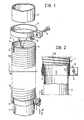
- Figure 1 is a partially exploded perspective view of a flexible metal hose assembly according to the present invention, and
- Figure 2 is a section taken on the line 11-11 of Figure 1.
- In Figure 1 is shown a flexible metal hose 1 which is intended to be inserted in the exhaust pipe of a motor vehicle engine. The two sections of the exhaust pipe which are to be connected by the flexible metal hose 1 are indicated 2. The hose 1 is constituted by a metal strip (for example, of stainless steel) which is wound into a helix to form a series of turns connected by folded edges of the strip (see Figure 2).
- The inner diameter of the hose 1 corresponds to outer diameter of the two
sections 2 of the exhaust pipe. Moreover, theends 3 of the hose 1 each have threelongitudinal cuts 4 which are equiangularly spaced from each other, in order to facilitate the insertion of twopipe sections 2 into the ends of the flexible hose 1. On each of these ends is mounted acollar 5 provided with aclamping bolt 6 for clamping thecorresponding pipe section 2 within the flexible hose. - In order to connect the hose 1 to the two
pipe sections 2, one of the twopipe sections 2 is first inserted within one end of the hose 1. The hose 1 is then deformed so as to bring its opposite end into correspondence with theother pipe section 2 so as to allow the insertion of this pipe section into the flexible hose 1. The latter consequently resumes its undeformed configuration. Thebolts 6 of thecollars 5 are then tightened to clamp the ends of the hose 1 over the twopipe sections 2, so as to ensure sealing against the escape of the gaseous fluid destined to flow through the hose. Thelongitudinal cuts 4 increase the deformability of the ends of the hose 1, further improving the sealing of the connections between the hose 1 and thepipe sections 2. - The particular seamed-turn structure of the hose 1 results in the presence of a helical groove 7 within the hose, which extends over the entire length of the hose itself. In order to prevent the escape of any gas along this groove, each end of the flexible hose is provided with a
rivet 8 which has its head located so as to block the helical passage defined by the internal groove 7 and the outer surface of thecorresponding pipe section 2. The distance of eachrivet 8 from the corresponding end of the hose 1 is slightly greater than the length of thecuts 4. - As is clear from Figure 1, the
collars 5 have a width greater than the length of thecuts 4 and eachrivet 8 also passes through the wall of thecorresponding collar 5, thus fixing it to the hose 1.
Claims (3)
Priority Applications (1)
| Application Number | Priority Date | Filing Date | Title |
|---|---|---|---|
| AT82830278T ATE14786T1 (en) | 1982-01-13 | 1982-11-09 | FLEXIBLE METAL HOSE ARRANGEMENT THROUGH WHICH GAS CONTAINING MEDIA FLOW WITH HIGH TEMPERATURES. |
Applications Claiming Priority (2)
| Application Number | Priority Date | Filing Date | Title |
|---|---|---|---|
| IT8252817U IT8252817V0 (en) | 1982-01-13 | 1982-01-13 | FLEXIBLE HOSE THAT CAN BE INSERTED IN A DUCT COVERED BY HIGH TEMPERATURE GASEOUS FLUIDS |
| IT5281782U | 1982-01-13 |
Publications (2)
| Publication Number | Publication Date |
|---|---|
| EP0083910A1 EP0083910A1 (en) | 1983-07-20 |
| EP0083910B1 true EP0083910B1 (en) | 1985-08-07 |
Family
ID=11277701
Family Applications (1)
| Application Number | Title | Priority Date | Filing Date |
|---|---|---|---|
| EP82830278A Expired EP0083910B1 (en) | 1982-01-13 | 1982-11-09 | Flexible metal hose assembly through which gaseous fluids flow at high temperature |
Country Status (6)
| Country | Link |
|---|---|
| US (1) | US4536019A (en) |
| EP (1) | EP0083910B1 (en) |
| AT (1) | ATE14786T1 (en) |
| DE (1) | DE3265275D1 (en) |
| FR (1) | FR2519728A3 (en) |
| IT (1) | IT8252817V0 (en) |
Families Citing this family (12)
| Publication number | Priority date | Publication date | Assignee | Title |
|---|---|---|---|---|
| JPH01165805U (en) * | 1988-05-13 | 1989-11-20 | ||
| WO1995020123A1 (en) * | 1994-01-24 | 1995-07-27 | Bks Company | Lap joint between flex hose and rigid pipe |
| IT240723Y1 (en) * | 1996-06-06 | 2001-04-11 | Gigi Molina Brevetti Plastici | MECHANICAL TIGHTENING COUPLING FOR CONNECTION TO A MAIN PIPE |
| US5924282A (en) * | 1998-01-20 | 1999-07-20 | Tru-Flex Metal Hose Corp. | Vehicle with improved exhaust system for internal combustion engine |
| US6341805B1 (en) * | 1998-03-17 | 2002-01-29 | Tru-Flex Metal Hose Corp | Vehicle exhaust system with improved pipe end configurations |
| DE19951947A1 (en) * | 1998-11-02 | 2000-05-04 | Luk Getriebe Systeme Gmbh | Hydraulic pressure system for operation of clutch or brake systems on road vehicle has flexible corrugated hose between cylinder connected to pedal and cylinder connected to clutch or brake |
| US6123369A (en) * | 1998-12-02 | 2000-09-26 | Donaldson Company, Inc. | Pipe lap joint and methods |
| US6508277B1 (en) | 1999-07-27 | 2003-01-21 | Donaldson Company, Inc. | Flexible pipe with compressed ends |
| US6843516B2 (en) * | 2002-07-15 | 2005-01-18 | H-P Products, Inc. | Coupler for low pressure piping system |
| CN102853189B (en) * | 2011-06-30 | 2014-09-03 | 新兴重工湖北三六一一机械有限公司 | Hose connecting device |
| JP5968796B2 (en) * | 2013-01-15 | 2016-08-10 | Ntn株式会社 | Boots band |
| CN113154162A (en) * | 2021-04-22 | 2021-07-23 | 江苏林诚电仪设备有限公司 | Adjustable-diameter end connector for hose |
Family Cites Families (19)
| Publication number | Priority date | Publication date | Assignee | Title |
|---|---|---|---|---|
| US510481A (en) * | 1893-12-12 | Bault | ||
| US591468A (en) * | 1897-10-12 | Hose fastening | ||
| GB600142A (en) * | 1945-09-28 | 1948-04-01 | Walter Leslie Gee | Improvements relating to means for coupling flexible metallic tubing to pipes or other tubular fittings or connections |
| FR394571A (en) * | ||||
| US817060A (en) * | 1905-04-24 | 1906-04-03 | Edwin T Greenfield | Hose. |
| US1005506A (en) * | 1910-05-16 | 1911-10-10 | William S Brown | Terminal connector or coupling for electric conduits. |
| US1340818A (en) * | 1916-09-11 | 1920-05-18 | Titeflex Metal Hose Corp | Flexible tube |
| GB175358A (en) * | 1920-11-05 | 1922-02-06 | Simplex Conduits Ltd | Improvements relating to continuity devices for metallic conduits and fittings for electric cables |
| US2474556A (en) * | 1945-11-23 | 1949-06-28 | Albert L Stone | Pipe joint seal |
| US2702716A (en) * | 1952-08-26 | 1955-02-22 | Lockheed Aircraft Corp | Slit socket clamped joint with compressed gasket |
| FR1253390A (en) * | 1959-12-31 | 1961-02-10 | Tubest Soc | Further development of flexible pipe fittings |
| US3365218A (en) * | 1965-01-25 | 1968-01-23 | Richard T. Denyes | Hose and clamp preassembly |
| US3408091A (en) * | 1966-05-23 | 1968-10-29 | Whirlpool Co | Coupling |
| US3407449A (en) * | 1967-03-03 | 1968-10-29 | Wittek Mfg Co | Hose clamp with hose-attaching means |
| DE2100952A1 (en) * | 1971-01-11 | 1972-07-20 | Oltmanns H | |
| US3944265A (en) * | 1974-11-15 | 1976-03-16 | Donaldson Company, Inc. | Exhaust system connector seal |
| US4142743A (en) * | 1977-01-31 | 1979-03-06 | Tru-Flex Metal Hose Corporation | Clamping device |
| US4165109A (en) * | 1978-01-03 | 1979-08-21 | Federal Hose Manufacturing Corp. | Wide-band compression coupling |
| US4176865A (en) * | 1978-03-21 | 1979-12-04 | Armco Steel Corporation | Coupling for pipe |
-
1982
- 1982-01-13 IT IT8252817U patent/IT8252817V0/en unknown
- 1982-10-08 FR FR8216943A patent/FR2519728A3/en active Granted
- 1982-11-09 EP EP82830278A patent/EP0083910B1/en not_active Expired
- 1982-11-09 DE DE8282830278T patent/DE3265275D1/en not_active Expired
- 1982-11-09 AT AT82830278T patent/ATE14786T1/en active
-
1983
- 1983-01-12 US US06/457,405 patent/US4536019A/en not_active Expired - Fee Related
Also Published As
| Publication number | Publication date |
|---|---|
| EP0083910A1 (en) | 1983-07-20 |
| ATE14786T1 (en) | 1985-08-15 |
| FR2519728A3 (en) | 1983-07-18 |
| DE3265275D1 (en) | 1985-09-12 |
| US4536019A (en) | 1985-08-20 |
| IT8252817V0 (en) | 1982-01-13 |
| FR2519728B3 (en) | 1983-12-02 |
Similar Documents
| Publication | Publication Date | Title |
|---|---|---|
| EP0083910B1 (en) | Flexible metal hose assembly through which gaseous fluids flow at high temperature | |
| US4779904A (en) | Couplings for connecting vehicle exhaust tail pipes to exhaust conduits for removing vehicle exhaust gases | |
| US5570737A (en) | Heat exchanger | |
| CA1106420A (en) | Wide-band compression coupling | |
| US4558891A (en) | Clamp for exhaust system | |
| US5069277A (en) | Vehicle-loaded heat exchanger of parallel flow type | |
| US4113289A (en) | Exhaust system and muffler lap joint | |
| FI67744B (en) | ANORDING FOR MAGNETIC BEHAVIOR WITH WATER COATING FOR GASFORM AND BRAENSLEN | |
| US6557908B2 (en) | Exhaust system clamp assembly and associated method | |
| US4147384A (en) | U-bolt clamp | |
| US20020079702A1 (en) | Flexible conduit element with a connection device attached to at least one end | |
| US5101889A (en) | Heat exchanger u-bend dipped joint with vent for clearance space | |
| US4249759A (en) | U-Bolt clamp | |
| US4898141A (en) | Fuel cooling device | |
| IE820553L (en) | Radiator | |
| US7198304B2 (en) | Fluid line connector with intermediate smooth surface | |
| US5768891A (en) | Exhaust system with scavenging venturi | |
| DE10322028A1 (en) | Refrigeration system with heat exchanger | |
| US4682647A (en) | Indicator device for a heat exchanger | |
| US6123369A (en) | Pipe lap joint and methods | |
| US6488313B1 (en) | Flexible connector assembly for exhaust system | |
| US5226476A (en) | Heat exchanger with bent inlet and outlet tube branches, and a method of making such branches | |
| US3416820A (en) | Motor vehicle accessory mounting | |
| JPH04281194A (en) | Oil cooler for motorcar | |
| US4953899A (en) | Clamp assembly |
Legal Events
| Date | Code | Title | Description |
|---|---|---|---|
| PUAI | Public reference made under article 153(3) epc to a published international application that has entered the european phase |
Free format text: ORIGINAL CODE: 0009012 |
|
| AK | Designated contracting states |
Designated state(s): AT DE GB SE |
|
| 17P | Request for examination filed |
Effective date: 19830505 |
|
| GRAA | (expected) grant |
Free format text: ORIGINAL CODE: 0009210 |
|
| AK | Designated contracting states |
Designated state(s): AT DE GB SE |
|
| PG25 | Lapsed in a contracting state [announced via postgrant information from national office to epo] |
Ref country code: AT Effective date: 19850807 |
|
| REF | Corresponds to: |
Ref document number: 14786 Country of ref document: AT Date of ref document: 19850815 Kind code of ref document: T |
|
| REF | Corresponds to: |
Ref document number: 3265275 Country of ref document: DE Date of ref document: 19850912 |
|
| PLBE | No opposition filed within time limit |
Free format text: ORIGINAL CODE: 0009261 |
|
| STAA | Information on the status of an ep patent application or granted ep patent |
Free format text: STATUS: NO OPPOSITION FILED WITHIN TIME LIMIT |
|
| 26N | No opposition filed | ||
| GBPC | Gb: european patent ceased through non-payment of renewal fee | ||
| PG25 | Lapsed in a contracting state [announced via postgrant information from national office to epo] |
Ref country code: GB Effective date: 19881122 |
|
| PG25 | Lapsed in a contracting state [announced via postgrant information from national office to epo] |
Ref country code: SE Effective date: 19891110 |
|
| PG25 | Lapsed in a contracting state [announced via postgrant information from national office to epo] |
Ref country code: DE Effective date: 19900801 |
|
| EUG | Se: european patent has lapsed |
Ref document number: 82830278.6 Effective date: 19900705 |