EP0083882A1 - Bezugsdruckanzeiger für Druckschalter - Google Patents
Bezugsdruckanzeiger für Druckschalter Download PDFInfo
- Publication number
- EP0083882A1 EP0083882A1 EP82402278A EP82402278A EP0083882A1 EP 0083882 A1 EP0083882 A1 EP 0083882A1 EP 82402278 A EP82402278 A EP 82402278A EP 82402278 A EP82402278 A EP 82402278A EP 0083882 A1 EP0083882 A1 EP 0083882A1
- Authority
- EP
- European Patent Office
- Prior art keywords
- pressure
- spring
- parallel
- front face
- movable
- Prior art date
- Legal status (The legal status is an assumption and is not a legal conclusion. Google has not performed a legal analysis and makes no representation as to the accuracy of the status listed.)
- Granted
Links
- 230000005540 biological transmission Effects 0.000 claims abstract description 9
- 230000006835 compression Effects 0.000 claims abstract description 9
- 238000007906 compression Methods 0.000 claims abstract description 9
- 239000004020 conductor Substances 0.000 claims abstract description 9
- 238000006073 displacement reaction Methods 0.000 claims abstract description 9
- 239000012530 fluid Substances 0.000 claims abstract description 8
- 239000000853 adhesive Substances 0.000 description 2
- 239000012528 membrane Substances 0.000 description 2
- 210000000056 organ Anatomy 0.000 description 2
- 230000001070 adhesive effect Effects 0.000 description 1
- 230000000295 complement effect Effects 0.000 description 1
- 230000008878 coupling Effects 0.000 description 1
- 238000010168 coupling process Methods 0.000 description 1
- 238000005859 coupling reaction Methods 0.000 description 1
- 210000004907 gland Anatomy 0.000 description 1
- 238000007789 sealing Methods 0.000 description 1
- 238000000926 separation method Methods 0.000 description 1
Images


Classifications
-
- H—ELECTRICITY
- H01—ELECTRIC ELEMENTS
- H01H—ELECTRIC SWITCHES; RELAYS; SELECTORS; EMERGENCY PROTECTIVE DEVICES
- H01H35/00—Switches operated by change of a physical condition
- H01H35/24—Switches operated by change of fluid pressure, by fluid pressure waves, or by change of fluid flow
- H01H35/26—Details
- H01H35/2607—Means for adjustment of "ON" or "OFF" operating pressure
-
- G—PHYSICS
- G01—MEASURING; TESTING
- G01D—MEASURING NOT SPECIALLY ADAPTED FOR A SPECIFIC VARIABLE; ARRANGEMENTS FOR MEASURING TWO OR MORE VARIABLES NOT COVERED IN A SINGLE OTHER SUBCLASS; TARIFF METERING APPARATUS; MEASURING OR TESTING NOT OTHERWISE PROVIDED FOR
- G01D13/00—Component parts of indicators for measuring arrangements not specially adapted for a specific variable
- G01D13/02—Scales; Dials
- G01D13/04—Construction
- G01D13/06—Moving bands
Definitions
- the invention relates to a pressure indicator device for a pressure switch comprising in a housing, a device sensitive to a fluid pressure in which this causes the displacement of a movable control member, a compression spring having a first end which communicates an effort to this member to balance the pressure and a second end cooperating with an adjustment device able to modify the compression of this spring, an electrical switch having a push button and internal connection terminals for receiving ends of electrical conductors, a transmission lever which communicates the movements of the movable member to this pusher, an indicator member which is linked to the displacements of the second end of the spring or to the adjustment device and comprises an index moving opposite a pressure scale, this housing having on its surface, on the one hand, a pressure orifice internally connected to the sensitive and external device laughing at a source of fluid pressure to be monitored, and a connection opening through which the electrical conductors pass, and on the other hand, a fixing face and a front face opposite the latter.
- Such an apparatus is intended for example to start and stop a compressor group whose engine is controlled by the switch and whose air tank is connected to the sensitive device in order to maintain the pressure of this tank at a certain level.
- Pressure indicator devices are already known for pressure switches having the general constitution mentioned above, in which the respective arrangements of the elements which constitute them do not allow easy assembly in the factory, nor rational use of the internal volume of the device. , due to the size of the known indicating devices.
- the invention therefore proposes to provide a set pressure indicator device for a compact pressure switch in which measures will be taken to increase the robustness, facilitate assembly in the factory, reduce the volume necessary for its movement.
- the indicator member comprises a flexible strip which circulates parallel to the front face of the housing in a transparent passage carried by a removable cover, one end of this strip, external to this passage , being coupled to a moving part which follows the movements of this second spring end.
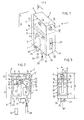
- the pressure switch 1 visible in Figure 1 has been broken down into a number of elementary volumes each receiving one of the elements or group of elements necessary for the performance of its function, and is shown in a position corresponding to that which will be recommended because of the direction in which a pressurized fluid line and an electrical connection cable will be connected later.
- the pressure switch 1 comprises a prismatic housing 2 see also Figures 2 and 3, the width m, measured between two vertical parallel side faces 3, 4, is substantially less than the height h measured vertically.
- a rear face 5, rectangular like a front space 13 which is opposite to it, is used for fixing the housing on a chassis or support 6 having a vertical plane Q which contains this face 5, see FIGS. 1 and 2.
- a device 9 sensitive to the pressure in which the latter causes the displacement of a mobile control member 10; in a second volume 11 located in an upper region 12 of the housing, which extends from the fixing face 5 to the front face 13, are placed a compression spring 14 and an adjustment device 15, 15 'accessible on the front face; in a third intermediate volume 16, placed between the two preceding volumes, is disposed a transmission lever 17 which communicates the movements and the position of the control member 10 to the pusher 18 of a switch 19 which is itself located in a fourth volume 20 placed between the first volume 7 and the front face 13, finally, a fifth volume 21 placed between the second, third and fourth volumes on the one hand, and the front face 13 on the other hand, receives an indicator member 22 the index of which cooperates with a scale 23 visible from the side of the front face, see FIG. 3.
- the fifth volume 21 extends to the second volume 12, because of the connections which will be established between the indicating member
- a pneumatic connection orifice 25 accessible from the bottom up, which is placed in the vicinity of the fixing face 5 and must receive a pipe end 26 for driving a pressure external to the device sensitive 9, as well as a passage opening 27 through which a cable or electrical conductors 28 will have to be connected to terminals of the switch; the orifice 25 is, moreover, placed closer to the plane Q, and to the fixing face 5, than is the opening 27 which is, it, closer to the front 13.
- control member 10 moves along an axis XX '
- compression spring 14 which is constituted by a helical spring
- the pusher 18 moves along an axis ZZ'
- the index of the indicator member 22 moves along an axis TT '
- the orifice 25 has an axis W'
- the opening 27 has an axis S5 '.
- the axis YY ' is substantially perpendicular to the plane Q, to the fixing face 5 and to the front face 13, and the axes XX', TT ', W' and SS ', are substantially parallel to each other and to the front face , see figure 2; moreover, all of these axes are substantially contained in a median plane PP ′, which passes equidistant from the parallel lateral faces 3 and 4 and which is perpendicular to the plane Q, see FIG. 3.
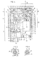
- the housing 2 comprises a hollow body 29 which has an interior space closed by a substantially planar cover 30, placed at the front of the housing to constitute the front face 13 opposite the fixing face 5.
- the pressure-sensitive device 9 comprises a control member constituted by one end 10 of a cylindrical rod 31 sliding along the axis XX 'in a bore 32 of the body.
- This rod is associated with a concentric pusher 33, a portion 34 of which passes through an opening 35 of an annular seat 36 which is placed in a second bore 37 from the concentric body to the first;
- one end of the pusher, opposite to the control member 10 has a head 38 of revolution which is placed in a first chamber 39 of the annular seat; this chamber is closed by a flexible membrane 40 the periphery of which is applied to the seat by an annular surface 41 of a plug 42 having a second chamber 43 opposite the first and connected by a channel 44 to the pneumatic connection orifice 25 whose axis is V Vt .
- This plug 42 is fixed to the body 29, for example using screws such as 45.
- this control member 10 is communicated to a support piece 47 belonging to a second lever 46, which is pivoted around a cylindrical pin 48 of axis WW ', perpendicular to the plane of the figure which is the plane median PP '; this lever also comprises, a lug 49 substantially parallel to the axis WW ', which is, in the rest position shown in this figure, supported on a boss 50 forming part of the bottom 51 of the body opposite the rear fixing face 5.
- This boss has a threaded hole 52 into which is screwed and blocked a first end 53 of a threaded rod 54 whose axis YY 'is perpendicular to the rear faces 5 and front 13.
- this threaded rod On the end 55 of this threaded rod opposite the first, is engaged a thread belonging to a nut 56 which also has a cylindrical housing 57 opposite the rod and an external shoulder 58.
- This nut constitutes an adjustment piece which will be moved by an adjustment member identified by 15 'in Figures 2 and 3 and described below.
- a washer 60 which has a radial extension 61 and a diametrically opposite notch 62, see in particular FIG. 5.
- This notch cooperates with an internal rib 98 of the body which is parallel to YY '.
- a helical spring 14 is placed concentrically at YY 'around the threaded rod and in such a way that a first end 14' is supported on the tab (49) and that a second end 14 "is supported on the washer 60 .
- This spring which is communicated via the first lever 46 to the control member 10, can subsequently, balance a force imparted to the latter by the fluid pressure.
- This compression of the spring can be adjusted by communicating with the nut 56 a rotation in one direction or the other; during this rotation, the washer 60 moves parallel to the axis YY 'and without rotating on itself.
- the rotation of this nut is obtained by virtue of the presence thereon of surfaces 63 parallel to the axis YY ', on which rest opposite ends of a pin 64 placed diametrically in one end 65 of a member adjustment 15 which enters the housing 57.
- These surfaces 63 can for example be carried by a notch 66 which passes through the wall 67 of the nut surrounding the housing 57, the end 65 then being placed coaxially in the housing , see also figure 6.
- the adjusting member 15 ′ has an external head 68 provided for example with a screwdriver slot 69 which will facilitate its operation, and a cylindrical surface 70 which is pivoted in a bearing 71 of the cover 30. Retaining means, such as 'a circlip, 72 make the adjustment member secured to the cover.
- the nut 56 and the adjustment member together constitute the adjustment device 15, 15 '.
- a flexible strip 85 is arranged in the corridor 83 in such a way that its end 86 which leaves the entry 84, is associated with the extension 61 of the washer 60 placed opposite, for example by virtue of an opening 87; the second end 88 of the ribbon which is placed in the first portion 79 carries an index 89 cooperating with the graduations 90 of a scale 23, see FIG. 7; this can be either engraved on the transparent portion, or preferably, carried by a self-adhesive label 91 which takes for example the shape of a rectangular frame whose periphery 32 covers the edges of the window and those of the transparent portion 76, thus ensuring sealing, see FIGS. 7 and 4.
- a second lever 93 extending substantially parallel to the axis YY 'and pivoting around a pin 94 of axis RR' perpendicular to the median plane P, has a first fulcrum 95 applied to a shoulder 96 of the control member and a second support point 97 opposite the first.
- This second movable fulcrum in a direction ZZ 'of the plane PP' substantially parallel to the axis XX ' is placed opposite a pusher 18 belonging to a switch 19 having connection terminals preferably directed towards the cover and adapted to receive ends of conductors 26.
- the pneumatic connection orifice 25 is placed like the pressure-sensitive device, in the vicinity of the fixing face 5, while the passage opening 27 is placed, like the switch, in the vicinity of the cover 30, this orifice and this opening opening onto the lower face 24.
- the transmission levers 104 respectively 105 must have an angled branch 106 respectively 107 to communicate to the pusher the movements of the ordered ; in order to obtain in FIG. 9 a movement of the branch 106 of the lever 104, capable of causing the push-button 100 to be pushed in, it may for example be necessary to place a pivot 108 of this lever 104 between the bottom 51 of the body and the control unit 10.
- the adjusting nut could be extended outwards by a cylindrical rod passing through an opening in the cover; this embodiment would however deprive the device of the benefit provided by a substantially flat front face, since this rod would exceed, depending on the set pressure selected, by a greater or lesser amount.
- a variant falls within the scope of the invention, as well as that where the flexible tape carries a movable ladder and where the fixed index is placed on the cover or on the window.
Landscapes
- Physics & Mathematics (AREA)
- Fluid Mechanics (AREA)
- General Physics & Mathematics (AREA)
- Measuring Fluid Pressure (AREA)
- Switches Operated By Changes In Physical Conditions (AREA)
Applications Claiming Priority (2)
| Application Number | Priority Date | Filing Date | Title |
|---|---|---|---|
| FR8123381 | 1981-12-15 | ||
| FR8123381A FR2518299B1 (fr) | 1981-12-15 | 1981-12-15 | Dispositif indicateur de pression de consigne pour un manostat |
Publications (2)
| Publication Number | Publication Date |
|---|---|
| EP0083882A1 true EP0083882A1 (de) | 1983-07-20 |
| EP0083882B1 EP0083882B1 (de) | 1986-03-26 |
Family
ID=9265035
Family Applications (1)
| Application Number | Title | Priority Date | Filing Date |
|---|---|---|---|
| EP82402278A Expired EP0083882B1 (de) | 1981-12-15 | 1982-12-14 | Bezugsdruckanzeiger für Druckschalter |
Country Status (5)
| Country | Link |
|---|---|
| EP (1) | EP0083882B1 (de) |
| DE (1) | DE3270181D1 (de) |
| DK (1) | DK555482A (de) |
| FR (1) | FR2518299B1 (de) |
| IT (1) | IT1205288B (de) |
Cited By (2)
| Publication number | Priority date | Publication date | Assignee | Title |
|---|---|---|---|---|
| US4796980A (en) * | 1986-04-02 | 1989-01-10 | Canon Kabushiki Kaisha | Ferroelectric liquid crystal optical modulation device with regions within pixels to initiate nucleation and inversion |
| EP0811830A1 (de) * | 1996-06-05 | 1997-12-10 | MERLONI TERMOSANITARI S.p.A. | Differential-Monostat, insbesondere für Gasboiler |
Citations (5)
| Publication number | Priority date | Publication date | Assignee | Title |
|---|---|---|---|---|
| US3543604A (en) * | 1968-10-30 | 1970-12-01 | Robertshaw Controls Co | Self-locking,adjustable limit stop means for a control device |
| DE2208678A1 (de) * | 1972-02-24 | 1973-08-30 | Honeywell Gmbh | Membrandruckschalter |
| FR2193245A1 (de) * | 1972-07-21 | 1974-02-15 | Telemecanique Electrique | |
| FR2333223A1 (fr) * | 1975-11-26 | 1977-06-24 | Mors Electricite | Indicateur electrique asservi a affichage lineaire |
| FR2380590A1 (fr) * | 1977-02-09 | 1978-09-08 | Ranco Inc | Commande reglable fonctionnant automatiquement suivant les variations d'un parametre |
-
1981
- 1981-12-15 FR FR8123381A patent/FR2518299B1/fr not_active Expired - Lifetime
-
1982
- 1982-12-14 DE DE8282402278T patent/DE3270181D1/de not_active Expired
- 1982-12-14 DK DK555482A patent/DK555482A/da not_active Application Discontinuation
- 1982-12-14 EP EP82402278A patent/EP0083882B1/de not_active Expired
- 1982-12-15 IT IT24774/82A patent/IT1205288B/it active
Patent Citations (5)
| Publication number | Priority date | Publication date | Assignee | Title |
|---|---|---|---|---|
| US3543604A (en) * | 1968-10-30 | 1970-12-01 | Robertshaw Controls Co | Self-locking,adjustable limit stop means for a control device |
| DE2208678A1 (de) * | 1972-02-24 | 1973-08-30 | Honeywell Gmbh | Membrandruckschalter |
| FR2193245A1 (de) * | 1972-07-21 | 1974-02-15 | Telemecanique Electrique | |
| FR2333223A1 (fr) * | 1975-11-26 | 1977-06-24 | Mors Electricite | Indicateur electrique asservi a affichage lineaire |
| FR2380590A1 (fr) * | 1977-02-09 | 1978-09-08 | Ranco Inc | Commande reglable fonctionnant automatiquement suivant les variations d'un parametre |
Cited By (2)
| Publication number | Priority date | Publication date | Assignee | Title |
|---|---|---|---|---|
| US4796980A (en) * | 1986-04-02 | 1989-01-10 | Canon Kabushiki Kaisha | Ferroelectric liquid crystal optical modulation device with regions within pixels to initiate nucleation and inversion |
| EP0811830A1 (de) * | 1996-06-05 | 1997-12-10 | MERLONI TERMOSANITARI S.p.A. | Differential-Monostat, insbesondere für Gasboiler |
Also Published As
| Publication number | Publication date |
|---|---|
| DK555482A (da) | 1983-06-16 |
| IT1205288B (it) | 1989-03-15 |
| EP0083882B1 (de) | 1986-03-26 |
| DE3270181D1 (en) | 1986-04-30 |
| FR2518299B1 (fr) | 1990-07-20 |
| FR2518299A1 (fr) | 1983-06-17 |
| IT8224774A0 (it) | 1982-12-15 |
Similar Documents
| Publication | Publication Date | Title |
|---|---|---|
| EP0776247A1 (de) | Pipette zum abgeben von aufeinanderfolgenden flüssigkeitsmengen | |
| EP0172117A2 (de) | Peristaltische Pumpe mit einer Druckmessungsvorrichtung | |
| FR2849429A1 (fr) | Bouchon de fermeture d'un flacon, a ouverture controlee | |
| EP0926974B1 (de) | Brühgetränkevorrichtung | |
| FR2636034A1 (fr) | Support a monter sur un guidon de bicyclette pour porter un instrument de poignet | |
| FR2535070A1 (fr) | Charniere a ressort pour monture de lunettes | |
| EP0066322B1 (de) | Bremsvorrichtung eines metallischen Messbandes | |
| EP1605122A1 (de) | Öffnungs- und Schliessmechanismus für Kraftfahrzeugtür | |
| EP0083882B1 (de) | Bezugsdruckanzeiger für Druckschalter | |
| EP0032098A1 (de) | Vorrichtung zum Entnehmen und Wiederabgeben wählbarer Flüssigkeitsmengen mit einer numerischen Anzeige | |
| EP0082064B1 (de) | Manostat kleiner Bauweise und von leichter Ausführung und Montage | |
| FR2579381A2 (fr) | Contact electrique a pression a pouvoir de fermeture et d'ouverture incorpore | |
| FR2470326A1 (fr) | Dispositif porte-orifice pour mesure de debit dans les canalisations sous pression | |
| EP0165362A1 (de) | Zirkel | |
| EP0446770B1 (de) | Wecker | |
| CH681488A5 (de) | ||
| EP0046830B1 (de) | Präzisionszirkel mit gelenkigem Schenkel und steifer Stange | |
| EP0575212B1 (de) | Vorrichtung zur Beseitigung von auf der Schauglasinnenseite eines Totalisators geformtem Beschlag | |
| FR2523763A1 (fr) | Dispositif amovible de verrouillage d'un contacteur dans sa position de travail | |
| FR2696775A1 (fr) | Perfectionnements aux poignées de porte à palettes basculantes. | |
| FR2621113A1 (fr) | Instrument de mesure, notamment pour jeux de boules | |
| FR2678732A1 (fr) | Thermometre a minimum et a maximum du type circulaire a aiguilles. | |
| EP1148529A1 (de) | Hilfseinheit zur Befestigung an einem elektrischen Schalter | |
| FR2622349A1 (fr) | Temporisateur a rearmement manuel | |
| FR2566057A1 (fr) | Pompe peristaltique a chargement automatique du tube |
Legal Events
| Date | Code | Title | Description |
|---|---|---|---|
| PUAI | Public reference made under article 153(3) epc to a published international application that has entered the european phase |
Free format text: ORIGINAL CODE: 0009012 |
|
| 17P | Request for examination filed |
Effective date: 19821215 |
|
| AK | Designated contracting states |
Designated state(s): DE GB |
|
| GRAA | (expected) grant |
Free format text: ORIGINAL CODE: 0009210 |
|
| AK | Designated contracting states |
Kind code of ref document: B1 Designated state(s): DE GB |
|
| REF | Corresponds to: |
Ref document number: 3270181 Country of ref document: DE Date of ref document: 19860430 |
|
| PLBE | No opposition filed within time limit |
Free format text: ORIGINAL CODE: 0009261 |
|
| STAA | Information on the status of an ep patent application or granted ep patent |
Free format text: STATUS: NO OPPOSITION FILED WITHIN TIME LIMIT |
|
| 26N | No opposition filed | ||
| PGFP | Annual fee paid to national office [announced via postgrant information from national office to epo] |
Ref country code: DE Payment date: 19981106 Year of fee payment: 17 |
|
| PGFP | Annual fee paid to national office [announced via postgrant information from national office to epo] |
Ref country code: GB Payment date: 19981208 Year of fee payment: 17 |
|
| PG25 | Lapsed in a contracting state [announced via postgrant information from national office to epo] |
Ref country code: GB Free format text: LAPSE BECAUSE OF NON-PAYMENT OF DUE FEES Effective date: 19991214 |
|
| GBPC | Gb: european patent ceased through non-payment of renewal fee |
Effective date: 19991214 |
|
| PG25 | Lapsed in a contracting state [announced via postgrant information from national office to epo] |
Ref country code: DE Free format text: LAPSE BECAUSE OF NON-PAYMENT OF DUE FEES Effective date: 20001003 |