EP0083530A1 - Method and device for the transfer of dangerous and/or radioactive substances - Google Patents
Method and device for the transfer of dangerous and/or radioactive substances Download PDFInfo
- Publication number
- EP0083530A1 EP0083530A1 EP82402361A EP82402361A EP0083530A1 EP 0083530 A1 EP0083530 A1 EP 0083530A1 EP 82402361 A EP82402361 A EP 82402361A EP 82402361 A EP82402361 A EP 82402361A EP 0083530 A1 EP0083530 A1 EP 0083530A1
- Authority
- EP
- European Patent Office
- Prior art keywords
- cell
- packaging
- installation according
- handling area
- matrix
- Prior art date
- Legal status (The legal status is an assumption and is not a legal conclusion. Google has not performed a legal analysis and makes no representation as to the accuracy of the status listed.)
- Withdrawn
Links
Images


Classifications
-
- G—PHYSICS
- G21—NUCLEAR PHYSICS; NUCLEAR ENGINEERING
- G21C—NUCLEAR REACTORS
- G21C19/00—Arrangements for treating, for handling, or for facilitating the handling of, fuel or other materials which are used within the reactor, e.g. within its pressure vessel
- G21C19/32—Apparatus for removing radioactive objects or materials from the reactor discharge area, e.g. to a storage place; Apparatus for handling radioactive objects or materials within a storage place or removing them therefrom
-
- Y—GENERAL TAGGING OF NEW TECHNOLOGICAL DEVELOPMENTS; GENERAL TAGGING OF CROSS-SECTIONAL TECHNOLOGIES SPANNING OVER SEVERAL SECTIONS OF THE IPC; TECHNICAL SUBJECTS COVERED BY FORMER USPC CROSS-REFERENCE ART COLLECTIONS [XRACs] AND DIGESTS
- Y02—TECHNOLOGIES OR APPLICATIONS FOR MITIGATION OR ADAPTATION AGAINST CLIMATE CHANGE
- Y02E—REDUCTION OF GREENHOUSE GAS [GHG] EMISSIONS, RELATED TO ENERGY GENERATION, TRANSMISSION OR DISTRIBUTION
- Y02E30/00—Energy generation of nuclear origin
- Y02E30/30—Nuclear fission reactors
Definitions
- the present invention relates to a method and an installation for the transfer of dangerous and / or radioactive materials, and more particularly of irradiated nuclear fuels.
- the irradiated assemblies are evacuated either directly to a reprocessing plant, or to a place of temporary storage while awaiting their transfer to the reprocessing plant.
- Transport is carried out in castles or armored packaging having the general shape of a cylinder of great length having an opening at one of its ends and comprising a protection against radiations, which makes them heavy and bulky.
- FIG. 1 illustrates the method currently used for the transfer of such packaging between the reactor 1 and a reception installation 2.
- the packaging 4 is approached by its upper opening against the lower wall of a room known as a "load cell" 6 using a packaging elevator (not shown).
- a lifting unit 9 placed inside the cell 6 is used to introduce the assemblies inside the castle 4 which is in a vertical position.
- the packaging is closed using an internal shutter operated from inside the cell 6.
- the packaging is then placed, using the elevator, on a tilting trolley 10 where we put in place its external shutter.
- the castle is then tilted in a horizontal position and the carriage 10 brings it under an overhead crane 11 equipped with a lifting beam 12 making it possible to lift the packaging.
- We reti re the carriage 10, and a wagon 13 is brought in its place on which the packaging is deposited, still horizontally, for transfer to a receiving installation 2.
- the packaging is then hung on an overhead crane 14 by means of a lifting beam 15, which allows it to be returned to the vertical position by lifting. It is then placed on a transporter-lift truck 16 and its external shutter is removed from it before bringing it opposite the opening of an unloading cell 17. The internal shutter is removed and the assemblies are extracted one by one.
- the object of the present invention is to avoid these drawbacks by means of a method and an installation for transferring dangerous and / or radioactive materials which facilitate the movement of transport packaging and make all the handling devices used in the prior art useless.
- the said materials are introduced into a heavy container and they are used to move them on the floor of a receiving cell and on that of a handling area as well as on a carried tray. by a transport vehicle, lift means for maintaining said container at a constant level on a flat surface for the duration of the transfers.
- This process can be used to transfer products requiring heavy packaging from a departure or arrival facility to a transport vehicle and vice versa. It can also be used to move dangerous materials contained in a heavy container inside an armored enclosure between different stations such as a filling station, a storage station and an extraction station, whether this enclosure is filled with air or a neutral gas.
- the products to be transferred are loaded inside a container or packaging, the latter having a determined position in space and being provided with a flat lower surface, the packaging is lifted by said lifting means, and it is moved over a horizontal handling area extending from the vicinity of the loading site to the parking point of a vehicle, the latter having a tray located substantially at the same level as the handling area, the trim of said packaging remaining constant throughout the duration of the transfer.
- the packaging may itself have a flat lower face, or be placed on a frame having a flat lower surface, and equipped with lifting means.
- the transport packaging is supported by fluid cushions, as is the ma loading china, the lid carrier trolley and the cork carrier trolley.
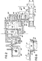
- Figure 2 If we refer to Figure 2, we see that it consists of two parts: the left part is a vertical sectional view showing how the irradiated assemblies 18 are transported vertically from the reactor vessel 20 to a storage pool 22 and from there, thanks to a handling device 23, in a room called "preparation cell" 24. This appears on the right part of the figure, which is a schematic plan view of the entire device object of the invention.
- the preparation cell 24 is separated from an armored cell called a "reception cell" 26 by a wall 27 pierced with an opening 28.
- the reception cell 26 is itself separated from the outside by a wall 30 pierced with an orifice 32.
- a loading machine 34 supported by fluid cushions, can move inside the receiving cell 26. Its role is to transport the loading dies, which are shaped containers cylindrical fitted with cells in which the assemblies to be transferred are arranged. These dies are introduced into the transport packaging.
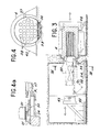
- the loading machine 34 appears better on the sectional view of FIG. 3. It can be seen that it comprises at its upper part a plate or shovel 36, movable by means of a chain 35, serving to support the matrix 37 and introduce it in the packaging 4.
- FIG. 4 shows the matrix 37, provided with cells 38, arranged inside the package 4. It can be seen that the matrix 37 carries a flat 39 in order to provide the bottom of the package with a space allowing the introduction of the shovel 36. Guide cheeks 40 carried by the machine 34 facilitate the introduction of the matrix 37 into the packaging.
- FIG. 4a shows the end of the shovel 36 carrying the matrix 37 when it enters the packaging 4. It can be seen that the fluid cushions with which it is equipped allow it to rest either on the upper surface 41 of the machine 34, or on a part 47 of the inner wall of the package 4.
- a carriage 42 known as a "gate holder", itself movable on a fluid cushion. It is used to maneuver the cover 43 which seals the orifice 32 when the packaging 4 is not being loaded or unloaded.
- the device comprises storage cells 29, communicating with the cell 26 by orifices 44 which can be closed by plugs 45.
- a plug-holder carriage 46 supported by fluid cushions and movable at the inside the cell 26, allows the plugs 45 to be removed and put in place.
- the role of these cells is to allow temporary storage of the full or empty dies if this proves necessary during the transfer operation.
- the cells are equipped with ventilation circuits (not shown) allowing the residual power of the radioactive products to be removed during storage.
- the packaging 4 is itself disposed on a frame 48 supported by fluid cushions (Figure 3).
- This frame can be moved over a handling area 50 (FIG. 2) to a transport vehicle 52 which, in the example shown here without limitation, is a rail car iron.
- a transport vehicle 52 which, in the example shown here without limitation, is a rail car iron.
- FIG. 2 This is best seen in the sectional view of Figure 5.
- a horizontal plate 51 on which is fixed, by means of flanges 53, the frame 48 supporting the packaging 4.
- means for example mechanical or hydraulic cylinders 54
- a removable plate 55 is used to make the connection between the plate 51 and the handling area 50.
- an empty matrix, carried by the loading machine 34 is brought in front of the opening 28 (FIG. 2).
- the assemblies are introduced into the cells of the matrix using a handling device contained in the preparation cell 24, then the machine 34 is moved until it is in front of an empty cell. and partially penetrates into the orifice of the cell until it is in contact.
- the shovel 36 is set in motion in order to introduce the matrix into the cell, then the machine 34 is removed and the carriage 46 comes to place the plug 45 used to close the cell.
- the shovel 36 is equipped with a lifting device by fluid cushions, which makes it possible to lift it during its relative movement relative to the machine 34.
- the wagon 52 which brings a package containing an empty matrix, is stopped at its parking point at the edge of the handling area 50.
- the jacks 54 (FIG. 5) are set in motion in order to bring the platform 51 of the wagon to the same level than the handling area.
- the plate 55 is put in place to make the junction between the area 50 and the plate 51.
- the immobilizing flanges 53 are unlocked, then a flexible pipe 56 (FIG. 2) is connected to a pressure tap in order to supply the frame 48 in compressed air (it is also possible to use a compressor on board a self-propelled cart.
- the entire package and its support frame are then moved to a preparation station 58, located on the handling area 50, where the front shock absorber is removed from the packaging as well as its external shutter.
- the "shock absorbers” are protective covers placed at the two ends of the packaging in order to protect it from accidental impact. and unloading the dies, it is necessary to remove the front shock absorber while the rear shock absorber can remain in place for the duration of the cycle.
- the compressed air supply is cut in order that the frame 48 rests On the ground. This supply is restarted for the movement of the assembly up to the orifice 32, which is closed by the cover 43.
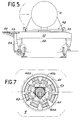
- the locking system of the latter appears in the sectional view of Figure 6.
- the orifice 32 and the cover 43 have a cylindrical shape and their axis XX ′ coincides with that of the packaging 4.
- the cover 43 is fitted, on the side outside, of a drive finger 60, maneuvered using a mechanism 62, and whose shape allows it to engage in a housing 64, provided on the outside face of the internal shutter 65.
- the finger 60 has substantially the shape of a square: it has been shown in the locked position (60a) above the axis XX 'and in the unlocked position (60b) below.
- Figure 7 shows the mechanism for fixing the shutter 65 on the package 4: the lower half of the figure corresponds to the locked position and the upper part to the unlocked position.
- Locking is ensured by means of locking fingers 61 maneuvered using cams 63, the movements of which are controlled by the rotation of the drive finger 60.
- the closure system of the cover 43 and the connection with the shutter 65 are material of the "Double sealed transfer door" type marketed by the company La Calhène under the name DPTE. Its main interest consists in protecting the surfaces, subsequently accessible, from radioactive contamination during the introduction of the seal-shutter assembly in the contaminated cell.
- the carriage 42, carrying the cover 43 and the shutter 65, is then moved and the loading machine 34 is brought in front of the orifice 32 (FIG. 3).
- the scoop 36 is introduced into the space provided between the packaging and the matrix to be unloaded.
- the lift circuit of the shovel is started, which has the effect of lifting the matrix. This is extracted from the packaging and the shovel 36 is brought back to the machine 34.
- the latter is then moved to an empty cell in which the empty matrix is introduced (the cells for storing the empty matrices do not have need to be closed with a plug).
- the stopper machine 46 is then brought in front of the cell containing the full matrix to be shipped ( Figure 2).
- the plug 45 is removed using a locking mechanism similar to that which has been described with reference to FIGS. 6 and 7, and then the plug holder machine is removed.
- the loading machine is brought in front of the cell and the matrix is extracted by a series of operations similar to what has been described above.
- the machine 34 is then brought back to the orifice 32 and the matrix is introduced into the packaging.
- the loading machine is removed and the cover carrier carriage 42 is brought in front of the orifice 32.
- the drive finger 60 By rotation of the drive finger 60, the cover 43 and the shutter 65 are replaced and disconnected.
- the cell is sealed by the cover 43, the packaging, by the shutter 65.
- the packaging still arranged horizontally on its support frame 48, is brought to the preparation station 58 where its external shutter is placed. and its front shock absorber. It is then transported to the platform 51 of the wagon 52 on which the frame 48 is fixed. after stopping its compressed air supply.
- the wagon is then dispatched to a reception facility (reprocessing or intermediate storage) where it can be unloaded using an identical device.
- the device according to the invention comprises a certain number of devices supported by fluid cushions.
- the supply of these with compressed air is only opened when they are moved: when they are stationary, during the loading or unloading stages, this supply is cut off and they always rest on the ground.
- This supply can be done by connection to a compressed air network or using a compressor on board the vehicle in question or on an accompanying vehicle.
- the method and the device according to the invention have numerous advantages, the main one being ease of handling since the transport packaging is placed on a frame itself supported by fluid cushions: the force of a few men is enough to move a mass of several tonnes on an air cushion, which makes it possible to remove all the bulky devices which were necessary with the methods of the prior art (overhead traveling cranes, tilting carriages, lifting beams, ferries, elevators, etc.).
- the lateral displacement can be carried out using a light self-propelled trolley, which can be fitted with an air compressor ensuring the supply of compressed air allowing the lift.
- Mobile devices inside the receiving cell can be simple and light, which reduces the cost.
- the fluid used will advantageously be the ambient air outside or the gas present inside the receiving cell.
- the package 4 rests in a horizontal position on a support frame 48, but one can very well envisage removing the support frame, the package itself comprising a flat surface allowing the air cushion to lift.
- the transport vehicle can be any provided that it has a horizontal platform: road platform, barge, etc. For the transfer between two armored cells not far from each other it can be deleted.
- a lock airlock 73 is provided at the edge of the handling area 50.
- the barge 72 and the walls of the airlock 73 have such a shape that the barge can be lifted by jacks 54 like the wagon 52 in FIG. 5.
- the water contained in the airlock 73 is at a lower level 74. After loading , and so that the barge can float freely after removing the jacks 54, it is necessary to raise the water to a higher level 75.
- the applications are not limited to the handling of nuclear fuels alone: on the contrary, the method and the device according to the invention can be used for the transport of any dangerous material requiring heavy protection such as: source of cobalt 60, waste radioactive, liquid effluents, etc ... and in general for the handling of all objects requiring a significant weight packaging and having to meet very strict safety standards for staff and populations.
Landscapes
- Physics & Mathematics (AREA)
- Engineering & Computer Science (AREA)
- Plasma & Fusion (AREA)
- General Engineering & Computer Science (AREA)
- High Energy & Nuclear Physics (AREA)
- Container Filling Or Packaging Operations (AREA)
- Packaging Of Machine Parts And Wound Products (AREA)
- Warehouses Or Storage Devices (AREA)
Abstract
Description
La présente invention, a pour objet un procédé et une installation pour le transfert de matières dangereuses et/ou radioactives, et plus particulièrement de combustibles nucléaires irradiés.The present invention relates to a method and an installation for the transfer of dangerous and / or radioactive materials, and more particularly of irradiated nuclear fuels.
A leur sortie du réacteur, les assemblages irradiés sont évacués soit directement vers une usine de retraitement, soit vers un lieu de stockage provisoire en attendant leur transfert à l'usine de retraitement. Le transport s'effectue dans des châteaux ou emballages blindés ayant la forme générale d'un cylindre de grande longueur présentant une ouverture à l'une de ses extrémités et comportant une protection contre les rayonnements, ce qui les rend lourds et encombrants.On leaving the reactor, the irradiated assemblies are evacuated either directly to a reprocessing plant, or to a place of temporary storage while awaiting their transfer to the reprocessing plant. Transport is carried out in castles or armored packaging having the general shape of a cylinder of great length having an opening at one of its ends and comprising a protection against radiations, which makes them heavy and bulky.
La figure 1 illustre la méthode actuellement utilisée pour le transfert de tels emballages entre le réacteur 1 et une installation de réception 2.FIG. 1 illustrates the method currently used for the transfer of such packaging between the
Sur la figure, on voit que l'emballage 4 est accosté par son ouverture supérieure contre la paroi inférieure d'un local dit "cellule de chargement" 6 à l'aide d'un ascenseur à emballage (non représenté). Une unité de levage 9 placée à l'intérieur de la cellule 6 sert à introduire les assemblages à l'intérieur du château 4 qui se trouve en position verticale. Une fois le chargement terminé, l'emballage est fermé à l'aide d'un obturateur interne manoeuvré depuis l'intérieur de la cellule 6. L'emballage est ensuite placé, à l'aide de l'ascenseur, sur un chariot basculeur 10 où l'on met en place son obturateur externe. Le château est ensuite basculé en position horizontale et le chariot 10 l'amène sous un pont roulant 11 équipé d'un palonnier 12 permettant de soulever l'emballage. On retire le chariot 10, et on amène à sa place un wagon 13 sur lequel l'emballage est déposé, toujours horizontalement, en vue de son transfert jusqu'à une installation de réception 2. L'emballage est alors accroché à un pont roulant 14 par l'intermédiaire d'un palonnier 15, ce qui permet de le remettre en position verticale par levage. Il est ensuite déposé sur un chariot transbordeur-élévateur 16 et on lui ret.ire son obturateur externe avant de l'amener en face de l'ouverture d'une cellule de déchargement 17. On retire l'obturateur interne et les assemblages sont extraits un par un.In the figure, it can be seen that the
On voit que l'ensemble de ces opérations exige de nombreuses reprises de charge et donc des appareils de manutention nombreux et encombrants, en particulier des ponts roulants de forte puissance et à course d'élévation importante. Il faut donc prévoir des bâtiments de grande hauteur et de forte résistance, calculés pour résister aux séismes, ce qui les rend très onéreux. De plus, cette suite d'opérations est assez longue à réaliser, ce qui entraîne des pertes de temps.It can be seen that all of these operations require numerous load recoveries and therefore numerous and bulky handling devices, in particular high-power overhead traveling cranes with a high lift stroke. It is therefore necessary to provide tall buildings and high strength, calculated to withstand earthquakes, which makes them very expensive. In addition, this sequence of operations is quite long to perform, which leads to loss of time.
La présente invention a pour but d'éviter ces inconvénients grâce à un procédé et une installation de transfert de matières dangereuses et/ou radioactives qui facilitent le déplacement des emballages de transport et rendent inutiles tous les appareils de manutention utilisés dans l'art antérieur.The object of the present invention is to avoid these drawbacks by means of a method and an installation for transferring dangerous and / or radioactive materials which facilitate the movement of transport packaging and make all the handling devices used in the prior art useless.
Selon la principale caractéristique du procédé objet de l'invention, on introduit lesdites matières dans un récipient pesant et on utilise pour les déplacer sur le sol d'une cellule de réception et sur celui d'une aire de manutention ainsi que sur un plateau porté par un véhicule de transport, des moyens de sustentation pour maintenir ledit récipient à un niveau constant sur une surface plane pendant la durée des transferts.According to the main characteristic of the process which is the subject of the invention, the said materials are introduced into a heavy container and they are used to move them on the floor of a receiving cell and on that of a handling area as well as on a carried tray. by a transport vehicle, lift means for maintaining said container at a constant level on a flat surface for the duration of the transfers.
Ce procédé peut être utilisé pour transférer des produits nécessitant des emballages de poids important depuis une installation de départ ou d'arrivée jusqu'à un véhicule de transport et inversement. Il peut aussi être utilisé pour déplacer des matières dangereuses contenues dans un récipient pesant à l'intérieur d'une enceinte blindée entre différents postes tels qu'un poste de remplissage, un poste de stockage et un poste d'extraction, que cette enceinte soit remplie d'air ou d'un gaz neutre.This process can be used to transfer products requiring heavy packaging from a departure or arrival facility to a transport vehicle and vice versa. It can also be used to move dangerous materials contained in a heavy container inside an armored enclosure between different stations such as a filling station, a storage station and an extraction station, whether this enclosure is filled with air or a neutral gas.
Dans le cas de transfert entre une installation de départ ou d'arrivée et un véhicule, on charge les produits à transférer à l'intérieur d'un récipient ou emballage, ce dernier ayant une position déterminée dans l'espace et étant muni d'une surface inférieure plane, on soulève l'emballage grâce auxdits moyens de sustentation, et on le déplace sur une aire de manutention horizontale s'étendant depuis le voisinage du lieu de chargement jusqu'au point de stationnement d'un véhicule, celui-ci ayant un plateau situé sensiblement au même niveau que l'aire de manutention, l'assiette dudit emballage restant constante pendant toute la durée du transfert.In the case of transfer between a departure or arrival installation and a vehicle, the products to be transferred are loaded inside a container or packaging, the latter having a determined position in space and being provided with a flat lower surface, the packaging is lifted by said lifting means, and it is moved over a horizontal handling area extending from the vicinity of the loading site to the parking point of a vehicle, the latter having a tray located substantially at the same level as the handling area, the trim of said packaging remaining constant throughout the duration of the transfer.
Suivant les cas l'emballage peut comporter lui-même une face inférieure plane, ou être posé sur un bâti ayant une surface inférieure plane, et équipée de moyens de sustentation.Depending on the case, the packaging may itself have a flat lower face, or be placed on a frame having a flat lower surface, and equipped with lifting means.
Il est ainsi très facile de déplacer l'emballage sur l'aire de manutention sans recourir à tout l'appareillage qui était nécessaire avec les méthodes de l'art antérieur. De plus, l'emballage gardant toujours la même assiette au cours du transfert, on gagne du temps en supprimant toutes les étapes où l'on modifiait sa position et on supprime les risques de chute lors des manutentions et en cas de séismes.It is thus very easy to move the packaging on the handling area without resorting to all the equipment which was necessary with the methods of the prior art. In addition, the packaging always keeping the same plate during the transfer, saving time by removing all stages where we changed its position and we eliminate the risk of falling during handling and in case of earthquakes.
L'invention a également pour objet une installation pour la mise en oeuvre de ce procédé. Dans le cas de transfert entre une installation de départ ou d'arrivée et un véhicule, le dispositif objet de l'invention comprend :
- - une aire de manutention horizontale s'étendant depuis le lieu de chargement de l'emballage jusqu'au point de stationnement du véhicule et
- - des moyens permettant d'amener le plateau du véhicule au même niveau que l'aire de manutention.
- - a horizontal handling area extending from the place of loading of the packaging to the vehicle parking point, and
- - Means for bringing the platform of the vehicle to the same level as the handling area.
Pour le transfert à l'intérieur d'une cellule blindée, l'installation comprend à l'intérieur de la cellule :
- - au moins un récipient ou matrice de transfert,
- - une machine de chargement équipée de moyens lui permettant de se déplacer à l'intérieur de la cellule et de moyens aptes à manoeuvrer ladite matrice,
- - un chariot porte-opercule, équipé de moyens permettant de le déplacer à l'intérieur de la cellule et apte à manoeuvrer un opercule destiné à obturer de manière étanche un orifice percé dans une paroi séparant la cellule de l'extérieur.
- - at least one container or transfer matrix,
- a loading machine equipped with means enabling it to move inside the cell and means capable of maneuvering said matrix,
- - A cover carrier cart, equipped with means for moving it inside the cell and capable of operating a cover intended to seal a hole drilled in a wall separating the cell from the outside.
L'installation peut comporter également :
- - au moins un alvéole de stockage communiquant avec la cellule par un orifice pouvant être obturé par un bouchon, et
- - un chariot porte-bouchon, équipé de moyens permettant de le déplacer à l'intérieur de la cellule, et de moyens permettant de manoeuvrer ledit bouchon.
- at least one storage cell communicating with the cell through an orifice which can be closed off by a plug, and
- - A stopper cart, equipped with means for moving it inside the cell, and means for maneuvering said stopper.
Selon une autre caractéristique importante de l'invention, l'emballage de transport est supporté par des coussins fluides, de même que la machine de chargement, le chariot porte-opercule et le chariot porte-bouchon.According to another important characteristic of the invention, the transport packaging is supported by fluid cushions, as is the ma loading china, the lid carrier trolley and the cork carrier trolley.
L'invention apparaîtra mieux à la lecture de la description qui va suivre, donnée à titre purement illustratif et nullement limitatif, en référence aux dessins annexés, dans lesquels :
- - la figure 1, déjà décrite, illustre un procédé de transfert d'assemblages combustibles irradiés selon l'art antérieur,
- - la figure 2 est une vue schématique dont la partie gauche est une vue en élévation illustrant le transfert d'assemblages irradiés du coeur du réacteur jusqu'au dispositif selon l'invention et la partie droite est une vue de dessus schématique et partiellement en coupe de ce même dispositif,
- - la figure 3 est une vue agrandie suivant la ligne III-III de la figure 2,
- - la figure 4 est une vue suivant la ligne IV-IV de la figure 3,
- - la figure 4a est une vue agrandie, semblable à la figure 3, montrant une extrémité de la pelle portée par la machine de chargement,
- - la figure 5 est une vue schématique en coupe suivant la ligne V-V de la figure 2 illustrant le cas où le véhicule de transport est un wagon de chemin de fer,
- - la figure 6 est une vue agrandie en coupe, semblable à la figure 3, montrant le système de verrouillage de l'obturateur interne de l'emballage sur l'opercule fermant l'orifice percé dans la paroi de la cellule de réception,
- - la figure 7 est une vue suivant la ligne VII-VII de la figure 6, et
- - la figure 8 est une vue semblable à la figure 5 dans le cas où le véhicule de transport est une barge.
- FIG. 1, already described, illustrates a method for transferring irradiated fuel assemblies according to the prior art,
- - Figure 2 is a schematic view, the left part is an elevational view illustrating the transfer of irradiated assemblies from the reactor core to the device according to the invention and the right part is a schematic top view and partially in section of this same device,
- FIG. 3 is an enlarged view along line III-III in FIG. 2,
- FIG. 4 is a view along line IV-IV of FIG. 3,
- FIG. 4a is an enlarged view, similar to FIG. 3, showing one end of the shovel carried by the loading machine,
- FIG. 5 is a schematic sectional view along the line VV of FIG. 2 illustrating the case where the transport vehicle is a railway wagon,
- FIG. 6 is an enlarged sectional view, similar to FIG. 3, showing the locking system of the internal shutter of the packaging on the cover closing the orifice pierced in the wall of the receiving cell,
- FIG. 7 is a view along line VII-VII of FIG. 6, and
- - Figure 8 is a view similar to Figure 5 in the case where the transport vehicle is a barge.
Si l'on se reporte à la figure 2, on voit que celle-ci se compose de deux parties : la partie gauche est une vue en coupe verticale montrant comment les assemblages irradiés 18 sont transportés verticalement depuis la cuve 20 du réacteur dans une piscine de stockage 22 et de là, grâce à un appareil de manutention 23, dans un local dit "cellule de préparation" 24. Celle-ci apparaît sur la partie droite de la figure, qui est une vue schématique en plan de l'ensemble du dispositif objet de l'invention.If we refer to Figure 2, we see that it consists of two parts: the left part is a vertical sectional view showing how the
On voit que la cellule de préparation 24 est séparée d'une cellule blindée dite "cellule de réception" 26 par une paroi 27 percée d'une ouverture 28. La cellule de réception 26 est elle-même séparée de l'extérieur par une paroi 30 percée d'un orifice 32. Une machine de chargement 34, supportée par des coussins fluides, peut se déplacer à l'intérieur de la cellule de réception 26. Son rôle est de transporter les matrices de chargement, qui sont des récipients de forme cylindrique équipés d'alvéoles dans lesquels sont disposés les assemblages à transférer. Ce sont ces matrices qui sont introduites cansl'emballage de transport.It can be seen that the
La machine de chargement 34 apparaît mieux sur la vue en coupe de la figure 3. On voit qu'elle comporte à sa partie supérieure un plateau ou pelle 36, mobile à l'aide d'une chaîne 35, servant à supporter la matrice 37 et à introduire celle-ci dans l'emballage 4.The
La figure 4 montre la matrice 37, munie d'alvéoles 38, disposée à l'intérieur de l'emballage 4. On voit que la matrice 37 porte un méplat 39 afin de ménager à la partie inférieure de l'emballage un espace permettant l'introduction de la pelle 36. Des joues de guidage 40 portées par la machine 34 facilitent l'introduction de la matrice 37 dans l'emballage.FIG. 4 shows the
La figure 4a montre l'extrémité de la pelle 36 portant la matrice 37 lorsqu'elle pénètre dans l'emballage 4. On voit que les coussins fluides dont elle est équipée lui permettent de prendre appui soit sur la surface supérieure 41dela machine 34, soit sur une partie 47 de la paroi interne de l'emballage 4.FIG. 4a shows the end of the
Si l'on se reporte à nouveau aux figures 2 et 3, on voit à l'intérieur de la cellule 26 un chariot 42, dit "porte-opercule", lui-même mobile sur coussin fluide. Il sert à manoeuvrer l'opercule 43 qui ferme de manière étanche l'orifice 32 lorsque l'emballage 4 n'ést pas en cours de chargement ou de déchargement.If we refer again to FIGS. 2 and 3, we can see inside the cell 26 a
On voit également sur la figure 2 que le dispositif comporte des alvéoles de stockage 29, communiquant avec la cellule 26 par des orifices 44 pouvant être fermés par des bouchons 45. Un chariot porte-bouchon 46, supporté par coussins fluides et mobile à l'intérieur de la cellule 26, permet de retirer et de mettre en place les bouchons 45. Le rôle de ces alvéoles est de permettre un stockage provisoire des matrices pleines ou vides si cela s'avérait nécessaire au cours de l'opération de transfert.It can also be seen in FIG. 2 that the device comprises
Les alvéoles sont équipés de circuits de ventilation (non représentés) permettant d'évacuer la puissance résiduelle des produits radioactifs durant le stockage.The cells are equipped with ventilation circuits (not shown) allowing the residual power of the radioactive products to be removed during storage.
L'emballage 4 est lui-même disposé sur un bâti 48 supporté par des coussins fluides (figure 3). Ce bâti peut être déplacé sur une aire de manutention 50 (figure 2) jusqu'à un véhicule de transport 52 qui, dans l'exemple représenté ici de manière non limitative, est un wagon de chemin de fer. Celui-ci apparaît mieux sur la vue en coupe de la figure 5. On voit qu'il est équipé d'un plateau horizontal 51 sur lequel est fixé, au moyen de brides 53, le bâti 48 supportant l'emballage 4. Comme le bâti est transporté sur coussin d'air jusque sur le plateau 51, il est nécessaire de prévoir des moyens (par exemple des vérins mécaniques ou hydrauliques 54) pour amener celui-ci au même niveau que l'aire de manutention. On utilise une plaque amovible 55 pour réaliser la jonction entre le plateau 51 et l'aire de manutention 50.The
On va maintenant décrire un exemple de cycle de transfert dans le cas où l'emballage amène une matrice vide, qui sera stockée dans l'un des alvéoles 29, et repart avec une matrice qui a été chargée antérieurement et stockée dans un autre alvéole.We will now describe an example of a transfer cycle in the case where the packaging brings an empty matrix, which will be stored in one of the
Pour réaliser ce chargement préliminaire, une matrice vide, portée par la machine de chargement 34 est amenée en face de l'ouverture 28 (figure 2). Les assemblages sont introduits dans les alvéoles de la matrice à l'aide d'un dispositif de manutention contenu dans la cellule de préparation 24, puis la machine 34 est déplacée jusqu'à ce qu'elle se trouve en face d'un alvéole vide et pénètre partiellement dans l'orifice de l'alvéole jusqu'à être en contact. La pelle 36 est mise en mouvement afin d'introduire la matrice dans l'alvéole, puis la machine 34 est retirée et le chariot 46 vient mettre en place le bouchon 45 servant à obturer l'alvéole. La pelle 36 est équipée d'un dispositif de sustentation par coussins fluides, ce qui permet de la soulever pendant son mouvement relatif par rapport à la machine 34.To carry out this preliminary loading, an empty matrix, carried by the
Au début du cycle de transfert, le wagon 52, qui amène un emballage contenant une matrice vide, est arrêté à son point de stationnement au bord de l'aire de manutention 50. Les vérins 54 (figure 5) sont mis en mouvement afin d'amener le plateau 51 du wagon au même niveau que l'aire de manutention. La plaque 55 est mise en place pour réaliser la jonction entre l'aire 50 et le plateau 51. On déverrouille les brides d'immobilisation 53, puis une tuyauterie souple 56 (figure 2) est branchée à une prise de pression afin d'alimenter le bâti 48 en air comprimé (on peut aussi utiliser un compresseur embarqué à bord d'un chariot automoteur. L'ensemble de l'emballage et de son bâti support est alors déplacé jusqu'à un poste de préparation 58, situé sur l'aire de manutention 50, où l'on retire l'amortisseur avantde2'emballage ainsi que son obturateur externe. Les "amortisseurs" sont des capots protecteurs placés aux deux extrémités de l'emballage afin de le protéger contre des chocs accidentels. Pour le chargement et le déchargement des matrices, il est nécessaire de retirer l'amortisseur avant alors que l'amortisseur arrière peut rester en place pendant toute la durée du cycle. Pendant le retrait de l'amortisseur avant, l'alimentation en air comprimé est coupée afin que le bâti 48 repose sur le sol. Cette alimentation est remise en route pour le déplacement de l'ensemble jusqu'à l'orifice 32, qui est fermé par l'opercule 43.At the start of the transfer cycle, the
Le système de verrouillage de ce dernier apparaît sur la vue en coupe de la figure 6. On voit la paroi 30 de la cellule de réception 26 et l'opercule 43, porté par le chariot 42, qui ferme l'orifice 32. L'orifice 32 et l'opercule 43 ont une forme cylindrique et leur axe XX' est confondu avec celui de l'emballage 4. L'opercule 43 est équipé, du côté extérieur, d'un doigt d'entraînement 60, manoeuvré à l'aide d'un mécanisme 62, et dont la forme lui permet de s'engager dans un logement 64, prévu sur la face extérieure de l'obturateur interne 65. Le doigt 60 a sensiblement la forme d'un carré : on l'a représenté en position de verrouillage (60a) au-dessus de l'axe XX' et en position de déverrouillage (60b) au-dessous. En position de verrouillage, l'une des diagonales du carré est placée verticalement et le doigt 60 ne peut être extrait car l'ouverture permettant de l'introduire dans le logement 64 est un carré de mêmes dimensions dont les côtés sont verticaux et horizontaux. Par rotation du doigt 60 à l'aide du mécanisme 62, on assure simultanément le déverrouillage de l'obturateur interne 65 par rapport à l'emballage 4, le verrouillage de cet obturateur sur l'opercule 43, et le déverrouillage de ce dernier par rapport à l'orifice 32.The locking system of the latter appears in the sectional view of Figure 6. We see the
La figure 7 montre le mécanisme permettant de fixer l'obturateur 65 sur l'emballage 4 : la moitié inférieure de la figure correspond à la position de verrouillage et la partie supérieure à la position de déverrouillage.Figure 7 shows the mechanism for fixing the
Le verrouillage est assuré à l'aide de doigts de verrouillage 61 manoeuvrés à l'aide de cames 63 dont les mouvements sont commandés par la rotation du doigt d'entraînement 60.Locking is ensured by means of locking
Le système de fermeture de l'opercule 43 et la solidarisation avec l'obturateur 65 sont du matériel du type "Double porte transfert étanche" commercialisé par la société La Calhène sous la dénomination DPTE. Son principal intérêt consiste à protéger les faces, ultérieurement accessibles, de la contamination radio-active pendant l'introduction de l'ensemble opercule-obturateur en cellule contaminée.The closure system of the
Le chariot 42, portant l'opercule 43 et l'obturateur 65, est ensuite déplacé et on amène la machine de chargement 34 en face de l'orifice 32 (figure 3). La pelle 36 est introduite dans l'espace ménagé entre l'emballage et la matrice à décharger. On met en route le circuit de sustentation de la pelle, ce qui a pour effet de soulever la matrice. Celle-ci est extraite de l'emballage et on ramène la pelle 36 sur la machine 34. Cette dernière est alors déplacée jusqu'à un alvéole vide dans lequel on introduit la matrice vide (les alvéoles de stockage des matrices vides n'ont pas besoin d'être obturés par un bouchon).The
La machine porte-bouchon 46 est alors amenée en face de l'alvéole contenant la matrice pleine à expédier (figure 2). Le bouchon 45 est enlevé grâce à un mécanisme de verrouillage semblable à celui qui a été décrit en référence aux figures 6 et 7, puis on retire la machine porte-bouchon.The
On amène la machine de chargement devant l'alvéole et on extrait la matrice par une suite d'opérations semblables à ce qui a été décrit plus haut. On ramène ensuite la machine 34 devant l'orifice 32 et on introduit la matrice dans l'emballage. On retire la machine de chargement et on amène le chariot porte-opercule 42 en face de l'orifice 32. Par rotation du doigt d'entraînement 60, l'opercule 43 et l'obturateur 65 sont remis en place et désolidarisés. La cellule est rendue étanche par l'opercule 43, l'emballage, par l'obturateur 65. L'emballage 4, toujours disposé horizontalement sur son bâti- support 48, est amené au poste de préparation 58 où on lui met son obturateur externe et son amortisseur avant. Il est ensuite transporté jusque sur le plateau 51 du wagon 52 sur lequel on fixe le bâti 48 après avoir arrêté son alimentation en air comprimé. Le wagon est ensuite expédié vers une installation de réception (retraitement ou stockage intermédiaire) où il peut être déchargé à l'aide d'un dispositif identique.The loading machine is brought in front of the cell and the matrix is extracted by a series of operations similar to what has been described above. The
Le dispositif selon l'invention comporte un certain nombre d'appareils supportés par des coussins fluides. Cependant, l'alimentation de ceux-ci en air comprimé n'est ouverte que lorsqu'on les déplace : lorsqu'ils sont immobiles, pendant les étapes de chargement ou de déchargement, cette alimentation est coupée et ils reposent toujours sur le sol. Cette alimentation peut se faire par branchement sur un réseau d'air comprimé ou à l'aide d'un compresseur embarqué sur le véhicule en question ou sur un véhicule accompagnateur.The device according to the invention comprises a certain number of devices supported by fluid cushions. However, the supply of these with compressed air is only opened when they are moved: when they are stationary, during the loading or unloading stages, this supply is cut off and they always rest on the ground. This supply can be done by connection to a compressed air network or using a compressor on board the vehicle in question or on an accompanying vehicle.
Le procédé et le dispositif selon l'invention présentent de nombreux avantages dont le principal est la facilité de manutention puisque l'emballage de transport est placé sur un bâti lui-même supporté par des coussins fluides : la force de quelques hommes suffit pour déplacer une masse de plusieurs tonnes sur coussin d'air, ce qui permet de supprimer tous les appareils encombrants qui étaient nécessaires avec les méthodes de l'art antérieur (ponts roulants, chariots basculeurs, palonniers, transbordeurs, élévateurs, etc...). Le déplacement latéral peut être effectué à l'aide d'un chariot automoteur léger, celui-ci pouvant être muni d'un compresseur d'air assurant la fourniture de l'air comprimé permettant la sustentation. Les appareils mobiles à l'intérieur de la cellule de réception peuvent être simples et légers, ce qui en diminue le coût. Le fluide utilisé sera avantageusement l'air ambiant à l'extérieur ou le gaz présent à l'intérieur de la cellule de réception.The method and the device according to the invention have numerous advantages, the main one being ease of handling since the transport packaging is placed on a frame itself supported by fluid cushions: the force of a few men is enough to move a mass of several tonnes on an air cushion, which makes it possible to remove all the bulky devices which were necessary with the methods of the prior art (overhead traveling cranes, tilting carriages, lifting beams, ferries, elevators, etc.). The lateral displacement can be carried out using a light self-propelled trolley, which can be fitted with an air compressor ensuring the supply of compressed air allowing the lift. Mobile devices inside the receiving cell can be simple and light, which reduces the cost. The fluid used will advantageously be the ambient air outside or the gas present inside the receiving cell.
D'autre part, le fait que les matrices et emballages gardent toujours la même assiette et la suppression d'appareils tels que les ponts roulants permet de diminuer la hauteur des batimentsd'où une appréciable économie dans la construction de ceux-ci. Quant à l'aire de manutention, elle doit présenter un état de surface soigné, mais, comme la surface nécessaire est moindre qu'avec les solutions précédentes, on réalise encore une économie.On the other hand, the fact that the dies and packaging always keep the same attitude and the elimination of devices such as overhead traveling cranes makes it possible to reduce the height of the buildings, hence an appreciable economy in the construction of these. As for the handling area, it must have a neat surface condition, but, as the surface area required is less than with the previous solutions, there is still a saving.
Enfin, sur le plan de la sécurité, on supprime les risques de chute d'objets lourds en cours de manutention ainsi que les risques de basculement puisque le centre de gravité des charges est abaissé. La durée de l'opération de transfert est réduite, ce qui diminue le temps pendant lequel le personnel est exposé aux radiations, et améliore la cadence de rotation des emballages.Finally, in terms of safety, the risks of falling heavy objects during handling are eliminated as well as the risks of tipping since the center of gravity of the loads is lowered. The duration of the transfer operation is reduced, which reduces the time during which the personnel is exposed to radiation, and improves the rate of rotation of the packages.
Il est bien entendu que l'invention ne se limite pas au seul exemple de réalisation qui vient d'être décrit, mais qu'on peut envisager des variantes sans sortir pour autant du cadre de l'invention. Dans cet exemple, l'emballage 4 repose en position horizontale sur un bâti support 48, mais on peut très bien envisager de supprimer le bâti support, l'emballage comportant lui-même une surface plane permettant la sustentation par coussin d'air. Le véhicule de transport peut être quelconque à condition de présenter un plateau horizontal : plateforme routière, barge, etc... Pour le transfert entre deux cellules blindées peu éloignées l'une de l'autre il pourra être supprimé.It is understood that the invention is not limited to the single embodiment which has just been described, but that variants can be envisaged without thereby departing from the scope of the invention. In this example, the
Dans le cas où le véhicule de transport est une barge 72 (figure 8), il est prévu un sas d'écluse 73 au bord de l'aire de manutention 50. La barge 72 et les parois du sas 73 ont une forme telle que la barge puisse être soulevée par des vérins 54 comme le wagon 52 de la figure 5. Lorsque la barge est vide et en appui sur les vérins 54, l'eau contenue dans le sas 73 se trouve à un niveau inférieur 74. Après chargement, et afin que la barge puisse flotter librement après retrait des vérins 54, il est nécessaire de monter l'eau jusqu'à un niveau supérieur 75.In the case where the transport vehicle is a barge 72 (FIG. 8), a
Enfin les applications ne se limitent pas à la seule manutention de combustibles nucléaires : au contraire, le procédé et le dispositif selon l'invention peuvent être utilisés pour le transport de toute matière dangereuse nécessitant une protection lourde telle que : source de cobalt 60, déchets radioactifs, effluents liquides, etc... et d'une manière générale à la manutention de tous objets nécessitant un emballage de poids important et devant répondre à des normes de sécurité très strictes pour les personnels et les populations.Finally, the applications are not limited to the handling of nuclear fuels alone: on the contrary, the method and the device according to the invention can be used for the transport of any dangerous material requiring heavy protection such as: source of
Claims (15)
Applications Claiming Priority (2)
| Application Number | Priority Date | Filing Date | Title |
|---|---|---|---|
| FR8124624 | 1981-12-31 | ||
| FR8124624A FR2519463A1 (en) | 1981-12-31 | 1981-12-31 | METHOD AND INSTALLATION FOR TRANSFERRING RADIOACTIVE MATERIALS |
Publications (1)
| Publication Number | Publication Date |
|---|---|
| EP0083530A1 true EP0083530A1 (en) | 1983-07-13 |
Family
ID=9265602
Family Applications (1)
| Application Number | Title | Priority Date | Filing Date |
|---|---|---|---|
| EP82402361A Withdrawn EP0083530A1 (en) | 1981-12-31 | 1982-12-22 | Method and device for the transfer of dangerous and/or radioactive substances |
Country Status (3)
| Country | Link |
|---|---|
| EP (1) | EP0083530A1 (en) |
| JP (1) | JPS58165097A (en) |
| FR (1) | FR2519463A1 (en) |
Cited By (1)
| Publication number | Priority date | Publication date | Assignee | Title |
|---|---|---|---|---|
| CN115417183A (en) * | 2022-09-19 | 2022-12-02 | 中广核工程有限公司 | Layout structure of spent fuel transportation factory building and hoisting method of spent fuel transportation container |
Citations (5)
| Publication number | Priority date | Publication date | Assignee | Title |
|---|---|---|---|---|
| DE2253232A1 (en) * | 1972-10-30 | 1974-05-02 | Siemens Ag | Fuel loading facility - for pressurised water reactor incorporating loading channel and storage bay |
| FR2260169A1 (en) * | 1974-02-06 | 1975-08-29 | Westinghouse Electric Corp | |
| US3910006A (en) * | 1973-06-07 | 1975-10-07 | Westinghouse Electric Corp | Fuel element handling arrangement and method |
| US4069923A (en) * | 1974-12-16 | 1978-01-24 | Ebasco Services Incorporated | Buoyancy elevator for moving a load in an industrial facility such as a nuclear power plant |
| FR2436475A1 (en) * | 1978-09-18 | 1980-04-11 | Kraftwerk Union Ag | Handling spent nuclear fuel caskets - by remote controlled manipulators with freedom of movement in two planes |
-
1981
- 1981-12-31 FR FR8124624A patent/FR2519463A1/en not_active Withdrawn
-
1982
- 1982-12-22 EP EP82402361A patent/EP0083530A1/en not_active Withdrawn
- 1982-12-29 JP JP57234873A patent/JPS58165097A/en active Pending
Patent Citations (5)
| Publication number | Priority date | Publication date | Assignee | Title |
|---|---|---|---|---|
| DE2253232A1 (en) * | 1972-10-30 | 1974-05-02 | Siemens Ag | Fuel loading facility - for pressurised water reactor incorporating loading channel and storage bay |
| US3910006A (en) * | 1973-06-07 | 1975-10-07 | Westinghouse Electric Corp | Fuel element handling arrangement and method |
| FR2260169A1 (en) * | 1974-02-06 | 1975-08-29 | Westinghouse Electric Corp | |
| US4069923A (en) * | 1974-12-16 | 1978-01-24 | Ebasco Services Incorporated | Buoyancy elevator for moving a load in an industrial facility such as a nuclear power plant |
| FR2436475A1 (en) * | 1978-09-18 | 1980-04-11 | Kraftwerk Union Ag | Handling spent nuclear fuel caskets - by remote controlled manipulators with freedom of movement in two planes |
Cited By (1)
| Publication number | Priority date | Publication date | Assignee | Title |
|---|---|---|---|---|
| CN115417183A (en) * | 2022-09-19 | 2022-12-02 | 中广核工程有限公司 | Layout structure of spent fuel transportation factory building and hoisting method of spent fuel transportation container |
Also Published As
| Publication number | Publication date |
|---|---|
| JPS58165097A (en) | 1983-09-30 |
| FR2519463A1 (en) | 1983-07-08 |
Similar Documents
| Publication | Publication Date | Title |
|---|---|---|
| EP2165340B1 (en) | Container for long-term storage with removable base | |
| EP2617040B1 (en) | Device for the dry handling of nuclear fuel assemblies | |
| EP2609029B1 (en) | Device for handling drums, equipment for transferring powder material, and transfer method | |
| EP0736470B1 (en) | Transfer installation of containers for products flowing by gravity | |
| EP0187557B1 (en) | Double barrier transfer device between a container and a confinement | |
| EP0212028B1 (en) | Transfer method for an object without interruption of confinement | |
| EP1974357A2 (en) | Method and device for closing in a water-filled pool a loaded case with irradiated nuclear fuel | |
| EP2329501B1 (en) | Device for handling a container for nuclear fuel assemblies | |
| EP0083530A1 (en) | Method and device for the transfer of dangerous and/or radioactive substances | |
| FR2728382A1 (en) | PROCESS FOR REMOVING BULKY COMPONENTS FROM THE INTERNAL EQUIPMENT OF A PRESSURE TANK OF A NUCLEAR INSTALLATION AND FOR COLLECTING THE DISASSEMBLED ELEMENTS | |
| FR3007883A1 (en) | SYSTEM AND METHOD FOR HANDLING AND CUTTING BOX CONTAINING RADIOACTIVE PRODUCTS | |
| EP0509897B1 (en) | Installation for incinerating hospital garbage | |
| EP0048671B1 (en) | Energy production installation comprising several fast neutron nuclear reactors and a fuel element exchange system | |
| FR2552581A1 (en) | SYSTEM FOR TRANSFERRING NUCLEAR COMBUSTIBLE ASSEMBLIES | |
| FR2648121A1 (en) | REMOTE AUTOSERRANT REMOTE CONTROL DEVICE FOR CYLINDRICAL FUTS | |
| FR2957334A1 (en) | PROCESS FOR PACKAGING AND DISPENSING A PLURALITY OF SUCCESSIVE FILLING PRESSURE FLUID BOTTLES | |
| FR2582438A1 (en) | Handling and transportation cask for nuclear fuel assemblies and installation comprising a cask of this type | |
| EP1193317B1 (en) | Installation for the heat treatment of metallic article loads | |
| FR2694122A1 (en) | Appts. for transporting radioactive elements - comprises closed vessel enclosing turntable which receives elements in individual tubes and rotates to discharge them. | |
| BE1008006A3 (en) | Method and device for assembly of turning a nuclear reactor fuel cold water. | |
| FR3107264A1 (en) | CONTAINER FOR STORING USED TIRES AND DROPPING THEM INTO A BUCKET | |
| FR2759996A1 (en) | Automatic transfer of refinery tube bundles to and from a cleaner unit | |
| WO2011092243A1 (en) | Charging air lock system for underground storage cell having the same cross section as said cell | |
| JPH0153760B2 (en) | ||
| WO2014140064A1 (en) | Integrated system for forming and transporting packaging assemblies, and the assembly, filling and disassembly stations thereof |
Legal Events
| Date | Code | Title | Description |
|---|---|---|---|
| PUAI | Public reference made under article 153(3) epc to a published international application that has entered the european phase |
Free format text: ORIGINAL CODE: 0009012 |
|
| AK | Designated contracting states |
Designated state(s): BE CH DE GB IT LI NL SE |
|
| 17P | Request for examination filed |
Effective date: 19831224 |
|
| STAA | Information on the status of an ep patent application or granted ep patent |
Free format text: STATUS: THE APPLICATION HAS BEEN WITHDRAWN |
|
| 18W | Application withdrawn |
Withdrawal date: 19850301 |
|
| RIN1 | Information on inventor provided before grant (corrected) |
Inventor name: VIVIEN, JEAN Inventor name: MOULIN, MAURICE Inventor name: BERNARD, JEAN |