EP0083248B1 - Apparatus for calculating auto-correlation coefficients - Google Patents
Apparatus for calculating auto-correlation coefficients Download PDFInfo
- Publication number
- EP0083248B1 EP0083248B1 EP82307001A EP82307001A EP0083248B1 EP 0083248 B1 EP0083248 B1 EP 0083248B1 EP 82307001 A EP82307001 A EP 82307001A EP 82307001 A EP82307001 A EP 82307001A EP 0083248 B1 EP0083248 B1 EP 0083248B1
- Authority
- EP
- European Patent Office
- Prior art keywords
- auto
- correlation
- values
- correlation coefficients
- memory
- Prior art date
- Legal status (The legal status is an assumption and is not a legal conclusion. Google has not performed a legal analysis and makes no representation as to the accuracy of the status listed.)
- Expired
Links
Images

Classifications
-
- G—PHYSICS
- G10—MUSICAL INSTRUMENTS; ACOUSTICS
- G10L—SPEECH ANALYSIS TECHNIQUES OR SPEECH SYNTHESIS; SPEECH RECOGNITION; SPEECH OR VOICE PROCESSING TECHNIQUES; SPEECH OR AUDIO CODING OR DECODING
- G10L15/00—Speech recognition
- G10L15/08—Speech classification or search
- G10L15/10—Speech classification or search using distance or distortion measures between unknown speech and reference templates
-
- G—PHYSICS
- G06—COMPUTING OR CALCULATING; COUNTING
- G06F—ELECTRIC DIGITAL DATA PROCESSING
- G06F17/00—Digital computing or data processing equipment or methods, specially adapted for specific functions
- G06F17/10—Complex mathematical operations
- G06F17/15—Correlation function computation including computation of convolution operations
-
- G—PHYSICS
- G10—MUSICAL INSTRUMENTS; ACOUSTICS
- G10L—SPEECH ANALYSIS TECHNIQUES OR SPEECH SYNTHESIS; SPEECH RECOGNITION; SPEECH OR VOICE PROCESSING TECHNIQUES; SPEECH OR AUDIO CODING OR DECODING
- G10L25/00—Speech or voice analysis techniques not restricted to a single one of groups G10L15/00 - G10L21/00
- G10L25/03—Speech or voice analysis techniques not restricted to a single one of groups G10L15/00 - G10L21/00 characterised by the type of extracted parameters
- G10L25/06—Speech or voice analysis techniques not restricted to a single one of groups G10L15/00 - G10L21/00 characterised by the type of extracted parameters the extracted parameters being correlation coefficients
Definitions
- This invention relates to an apparatus for calculating auto-correlation coefficients and to an auto-correlation unit for pattern recognition using auto-correlation coefficients for stored signal samples.
- ⁇ indicates the degree of the auto-correlation coefficient sought to be calculated.
- the invention aims to provide circuitry which can calculate approximate auto-correlation coefficients by squaring the sum of X n and X n- ⁇ without the use of a multiplier where X n , X n - T are stored signal samples.
- Equation (9) reveals that the approximated value of the auto-correlation coefficient becomes available by squaring the sum of the input samples.
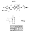
- an adder 1 which adds sample values X n and X n- ⁇ expressed with a required accuracy of multiple bits (e.g. 8 bit) and the output (maximum: 9 bits) of the adder 1 is fed to a ROM 2 (read only memory) in the next stage as an address signal for the ROM 2.
- the memory ROM 2 is designed so as to deliver the square in the form of an 18 bit output, when addressed by the 9 bit input signal representing (X n +X n- ⁇ ) from the adder 1.
- An adder 3 is further provided which repeatedly (n times) adds the squared value recieved from the ROM 2 with the memory contents of the RAM 4, in which the previous accumulated results are memorized.
- the results (X n +X n- ⁇ ) 2 is finally stored in a region "a" of memory 4.
- a calculation unit 5 is provided to calculate the auto-correlation coefficient C by executing operations according to equation (9), based on the following squared cumulative values memorized in memory 4: and
- the auto-correlation coefficients used as feature parameters in pattern recognition of voice recognition systems can be approximately obtained by simple circuitry which is generally set up by the adder, the ROM and the one or more RAM's.
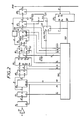
- Fig. 2 details the scheme of the auto-correlation unit as shown in Fig. 1.
- This circuit generally includes an amplifier, an analog to digital converter, a ROM and RAM's, a central processing unit CPU for executing of approximation of the correlation coefficient and a timing generator for generation of various timing signals.
- An analog signal (voice input) is amplified via the amplifier 10 and converted into an 8-bit binary offset code signal via the converter 11.
- f. provides a start pulse to the analog to digital converter and a write pulse for the RAM 13.
- the resultant signal X " is held in a latch 12 responsive to f k and loaded into the RAM 13, while providing an A input to an adder 14 (corresponding to the adder 1 in Fig. 1).
- the RAM 13 is to store X n- ⁇ which in turn is outputted data X n- ⁇ with a delay T in response to an address AD specified from the timing generator. Because of AD being 4 bits long, the RAM 13 is capable of storing data up to X n-15 .
- the output of the RAM 13 is also 8 bits and fed to a B input to the adder 14 which in turn adds the latter to the A input thereof and results in X n +X n- ⁇ .
- the result of such addition i.e. the sum X n +X n- ⁇ , is 9 bits including a carry bit.
- the ROM 15 is accessed by the resulting 9 bit output to fetch (X n +X n- ⁇ ) 2 which has previously been stored therein.
- the reason why X n +X n- ⁇ is stored in address A lo -A 2 of the ROM is due to the facts that (X n +X n- ⁇ ) 2 consists of 32 bits and is divided into 4 groups in outputting the same. For such grouping signals f 1 and f 2 are fed from the timing generator to A o and A 1 .
- the following describes a calculation circuit for evaluating ⁇ (X n +X n- ⁇ ) 2 , which circuit includes selectors 16 and 17, an adder 18, the RAM 22, buffers 21 and 23 and a clear gate 20.
- the 8 bit output of the ROM 15 is further divided into two groups and addition is effected every 4 bits in evaluating ⁇ (X n +X n- ⁇ ) 2 .
- the selectors S 1 and S 2 decide if signals under processing are the upper 4 bits or lower 4 bits of the 8 bit output of the ROM as selected by the least significant bit of the address ADS of the RAM 22.
- the address ADS is established through the timing generator 26.
- ⁇ (X n +X n- ⁇ ) 2 is calculated.
- the signals s 1 and s 2 are initially 00, addressing the lower 8 bits of (X n +X n- ⁇ ) 2 .
- the output of the ROM is Y 7 ⁇ Y 0 .
- the least significant bit of ADS selects the lower 4 bits so that Y 2 -Y o are fed to the B input of the adder 18 which also receives at its A input the lower 4 bits of ⁇ (X n +X n- ⁇ ) 2 currently fed from the RAM 22 through operation of the timing generator.
- the adder 18 seeks the sum of both the lower 4 bits and the results of such addition including a carry CA is held at a latch 19 in response to CA is the carry for the following 4 bit addition and CO is a carry originating during the lower 4 bit addition. The latter need be "0" during the lower 4 bit addition and this demand is satisfied by f 3 from the timing generator.
- the results of calculation held by the latch 19 except the carry are loaded into the RAM 22.
- the buffer 21 is of a tri-state type and shows a high impedance except during writing of the RAM 22. This timing requirement is determined by f s .
- the address ADS of the RAM 22 is updated with the lowest bit thereo selecting the upper 4 bits.
- the upper 4 bit calculation is carried out in the same timed manner as with the lower 4 bit calculation. Calculation on the outputs Y 7 -Y o of the ROM is completed in this manner. Thereafter, f 1 and f 2 becomes "10" so that calculation proceeds in the order of the lower 4 bits and upper 4 bits with the result ⁇ (X n +X n- ⁇ ) 2 being placed into the RAM 22. This is true when f 1 , f 2 are "01".
- ⁇ (X n +X n- ⁇ ) 2 is calculated (n) times and the results of such calculations are written into the RAM 22.
- the timing generator informs the CPU of the end of calculation and at the same time renders S 3 operative so that the RAM 22 is accessible from the CPU. This is achieved with a signal INT from the timing generator. That is, the CPU is interrupted by the signal INT and fetches from the RAM 22. Because only the lower 4 bits of the resultant data are in effect, data matching is necessary.
- the correlation coefficient is obtained under the approximation as defined by equation (9).
- ⁇ is a basic clock of 2.5 MHz (a pulse width of 200 ns).
- AD 3 -AD O are decremented at the start of each time frame and then incremented sequentially in the above manner.
- f k and have a pulse width of 200 ns and a frequency of 8 KHz.
- ADR 6 -ADR 3 are sequentially incremented as is clear from Fig. 4. and T s are not developed while INT is active.
- this invention offers a highly cost effective auto-correlation unit for pattern recognition with simple circuitry without the need to use an expensive multiplier, but which has comparatively high accuracy and can, moreover, calculate auto-correlation coefficients at high speed.
Landscapes
- Engineering & Computer Science (AREA)
- Physics & Mathematics (AREA)
- General Physics & Mathematics (AREA)
- Mathematical Physics (AREA)
- Computational Mathematics (AREA)
- Mathematical Analysis (AREA)
- Mathematical Optimization (AREA)
- Pure & Applied Mathematics (AREA)
- Theoretical Computer Science (AREA)
- Data Mining & Analysis (AREA)
- Software Systems (AREA)
- Databases & Information Systems (AREA)
- Computing Systems (AREA)
- General Engineering & Computer Science (AREA)
- Algebra (AREA)
- Computational Linguistics (AREA)
- Health & Medical Sciences (AREA)
- Audiology, Speech & Language Pathology (AREA)
- Human Computer Interaction (AREA)
- Acoustics & Sound (AREA)
- Multimedia (AREA)
- Complex Calculations (AREA)
- Image Analysis (AREA)
Applications Claiming Priority (2)
| Application Number | Priority Date | Filing Date | Title |
|---|---|---|---|
| JP210296/81 | 1981-12-29 | ||
| JP56210296A JPS58115492A (ja) | 1981-12-29 | 1981-12-29 | パタ−ン認識用自己相関器 |
Publications (3)
| Publication Number | Publication Date |
|---|---|
| EP0083248A2 EP0083248A2 (en) | 1983-07-06 |
| EP0083248A3 EP0083248A3 (en) | 1985-05-29 |
| EP0083248B1 true EP0083248B1 (en) | 1988-11-23 |
Family
ID=16587043
Family Applications (1)
| Application Number | Title | Priority Date | Filing Date |
|---|---|---|---|
| EP82307001A Expired EP0083248B1 (en) | 1981-12-29 | 1982-12-30 | Apparatus for calculating auto-correlation coefficients |
Country Status (4)
| Country | Link |
|---|---|
| US (1) | US5007101A (enExample) |
| EP (1) | EP0083248B1 (enExample) |
| JP (1) | JPS58115492A (enExample) |
| DE (1) | DE3279237D1 (enExample) |
Families Citing this family (8)
| Publication number | Priority date | Publication date | Assignee | Title |
|---|---|---|---|---|
| JPS62274471A (ja) * | 1986-05-23 | 1987-11-28 | Fanuc Ltd | 画像処理装置 |
| JPH0475183A (ja) * | 1990-07-17 | 1992-03-10 | Mitsubishi Electric Corp | 画像の相関度検出装置 |
| US5282134A (en) * | 1991-08-19 | 1994-01-25 | Automotive Systems Laboratory, Inc. | Slant transform/signal space crash discriminator |
| US5398303A (en) * | 1992-02-28 | 1995-03-14 | Yamatake-Honeywell Co., Ltd. | Fuzzy data processing method and data smoothing filter |
| US5361307A (en) * | 1993-03-25 | 1994-11-01 | General Electric Company | Correlation methods of identifying defects in imaging devices |
| WO1996028794A1 (en) * | 1995-03-10 | 1996-09-19 | Hitachi, Ltd. | Three-dimensional graphic display device |
| JP3276547B2 (ja) * | 1995-12-01 | 2002-04-22 | シャープ株式会社 | 画像認識方法 |
| US5970461A (en) * | 1996-12-23 | 1999-10-19 | Apple Computer, Inc. | System, method and computer readable medium of efficiently decoding an AC-3 bitstream by precalculating computationally expensive values to be used in the decoding algorithm |
Family Cites Families (2)
| Publication number | Priority date | Publication date | Assignee | Title |
|---|---|---|---|---|
| US4301329A (en) * | 1978-01-09 | 1981-11-17 | Nippon Electric Co., Ltd. | Speech analysis and synthesis apparatus |
| JPS5918717B2 (ja) * | 1979-02-28 | 1984-04-28 | ケイディディ株式会社 | 適応形ピツチ抽出方式 |
-
1981
- 1981-12-29 JP JP56210296A patent/JPS58115492A/ja active Granted
-
1982
- 1982-12-28 US US06/454,022 patent/US5007101A/en not_active Expired - Lifetime
- 1982-12-30 EP EP82307001A patent/EP0083248B1/en not_active Expired
- 1982-12-30 DE DE8282307001T patent/DE3279237D1/de not_active Expired
Also Published As
| Publication number | Publication date |
|---|---|
| US5007101A (en) | 1991-04-09 |
| JPS58115492A (ja) | 1983-07-09 |
| EP0083248A3 (en) | 1985-05-29 |
| EP0083248A2 (en) | 1983-07-06 |
| JPS634199B2 (enExample) | 1988-01-27 |
| DE3279237D1 (en) | 1988-12-29 |
Similar Documents
| Publication | Publication Date | Title |
|---|---|---|
| US5189712A (en) | Correlation detector for images | |
| US6708149B1 (en) | Vector fixed-lag algorithm for decoding input symbols | |
| EP0083248B1 (en) | Apparatus for calculating auto-correlation coefficients | |
| US5208770A (en) | Accumulation circuit having a round-off function | |
| US4255794A (en) | Digital filter | |
| US4775951A (en) | Correlation function computing device | |
| US4884229A (en) | Method and apparatus for removing noise | |
| EP0335306B1 (en) | Method and device for obtaining in real time the two-dimensional discrete cosine transform | |
| US4750190A (en) | Apparatus for using a Leroux-Gueguen algorithm for coding a signal by linear prediction | |
| EP0037130B1 (en) | Arrangement for calculating the discrete fourier transform by means of two circular convolutions | |
| US4588980A (en) | Residue to analog converter | |
| US4584561A (en) | Method of residue to analog conversion | |
| US5168456A (en) | Incremental frequency domain correlator | |
| KR0124367B1 (ko) | 디지탈 필터 | |
| KR0136517B1 (ko) | 비트단위의 파이프라인을 이용한 웨이브렛 변환 프로세서 | |
| KR910007728B1 (ko) | 패턴인식장치 | |
| US5701262A (en) | Tab coefficient updating device of finite impulse-responding adaptive digital filter | |
| US6314132B1 (en) | Microprocessor structure and method for implementing digital filter operations | |
| SU1564647A1 (ru) | Устройство дл адаптивной обработки информации | |
| SU938266A1 (ru) | Устройство дл определени динамических характеристик | |
| KR950009765B1 (ko) | 스퀘어롬을 이용한 디지탈 필터용 승산기 및 이를 포함한 유한 임펄스 응답(fir) 디지탈 필터 | |
| EP0178082A2 (en) | Digital correlator circuit | |
| SU1716607A1 (ru) | Цифровой фильтр с многоуровневой дельта-модул цией | |
| JPH08287037A (ja) | デジタル信号処理プロセッサ | |
| KR0136486B1 (ko) | 변형 부스 곱셈기 |
Legal Events
| Date | Code | Title | Description |
|---|---|---|---|
| PUAI | Public reference made under article 153(3) epc to a published international application that has entered the european phase |
Free format text: ORIGINAL CODE: 0009012 |
|
| AK | Designated contracting states |
Designated state(s): DE FR GB IT |
|
| PUAL | Search report despatched |
Free format text: ORIGINAL CODE: 0009013 |
|
| AK | Designated contracting states |
Designated state(s): DE FR GB IT |
|
| 17P | Request for examination filed |
Effective date: 19851104 |
|
| 17Q | First examination report despatched |
Effective date: 19861222 |
|
| GRAA | (expected) grant |
Free format text: ORIGINAL CODE: 0009210 |
|
| ITF | It: translation for a ep patent filed | ||
| AK | Designated contracting states |
Kind code of ref document: B1 Designated state(s): DE FR GB IT |
|
| REF | Corresponds to: |
Ref document number: 3279237 Country of ref document: DE Date of ref document: 19881229 |
|
| ET | Fr: translation filed | ||
| PLBE | No opposition filed within time limit |
Free format text: ORIGINAL CODE: 0009261 |
|
| STAA | Information on the status of an ep patent application or granted ep patent |
Free format text: STATUS: NO OPPOSITION FILED WITHIN TIME LIMIT |
|
| 26N | No opposition filed | ||
| ITTA | It: last paid annual fee | ||
| PGFP | Annual fee paid to national office [announced via postgrant information from national office to epo] |
Ref country code: FR Payment date: 20011212 Year of fee payment: 20 |
|
| REG | Reference to a national code |
Ref country code: GB Ref legal event code: IF02 |
|
| PGFP | Annual fee paid to national office [announced via postgrant information from national office to epo] |
Ref country code: GB Payment date: 20020102 Year of fee payment: 20 |
|
| PGFP | Annual fee paid to national office [announced via postgrant information from national office to epo] |
Ref country code: DE Payment date: 20020109 Year of fee payment: 20 |
|
| PG25 | Lapsed in a contracting state [announced via postgrant information from national office to epo] |
Ref country code: GB Free format text: LAPSE BECAUSE OF EXPIRATION OF PROTECTION Effective date: 20021229 |
|
| REG | Reference to a national code |
Ref country code: GB Ref legal event code: PE20 Effective date: 20021229 |