EP0083107A2 - Bildverarbeitungsanlage mit synthetischer Apertur - Google Patents
Bildverarbeitungsanlage mit synthetischer Apertur Download PDFInfo
- Publication number
- EP0083107A2 EP0083107A2 EP82112066A EP82112066A EP0083107A2 EP 0083107 A2 EP0083107 A2 EP 0083107A2 EP 82112066 A EP82112066 A EP 82112066A EP 82112066 A EP82112066 A EP 82112066A EP 0083107 A2 EP0083107 A2 EP 0083107A2
- Authority
- EP
- European Patent Office
- Prior art keywords
- range
- azimuth
- curvature compensation
- generating
- reference function
- Prior art date
- Legal status (The legal status is an assumption and is not a legal conclusion. Google has not performed a legal analysis and makes no representation as to the accuracy of the status listed.)
- Granted
Links
Images


Classifications
-
- G—PHYSICS
- G01—MEASURING; TESTING
- G01S—RADIO DIRECTION-FINDING; RADIO NAVIGATION; DETERMINING DISTANCE OR VELOCITY BY USE OF RADIO WAVES; LOCATING OR PRESENCE-DETECTING BY USE OF THE REFLECTION OR RERADIATION OF RADIO WAVES; ANALOGOUS ARRANGEMENTS USING OTHER WAVES
- G01S13/00—Systems using the reflection or reradiation of radio waves, e.g. radar systems; Analogous systems using reflection or reradiation of waves whose nature or wavelength is irrelevant or unspecified
- G01S13/88—Radar or analogous systems specially adapted for specific applications
- G01S13/89—Radar or analogous systems specially adapted for specific applications for mapping or imaging
- G01S13/90—Radar or analogous systems specially adapted for specific applications for mapping or imaging using synthetic aperture techniques, e.g. synthetic aperture radar [SAR] techniques
- G01S13/9004—SAR image acquisition techniques
- G01S13/9011—SAR image acquisition techniques with frequency domain processing of the SAR signals in azimuth
-
- G—PHYSICS
- G01—MEASURING; TESTING
- G01S—RADIO DIRECTION-FINDING; RADIO NAVIGATION; DETERMINING DISTANCE OR VELOCITY BY USE OF RADIO WAVES; LOCATING OR PRESENCE-DETECTING BY USE OF THE REFLECTION OR RERADIATION OF RADIO WAVES; ANALOGOUS ARRANGEMENTS USING OTHER WAVES
- G01S13/00—Systems using the reflection or reradiation of radio waves, e.g. radar systems; Analogous systems using reflection or reradiation of waves whose nature or wavelength is irrelevant or unspecified
- G01S13/88—Radar or analogous systems specially adapted for specific applications
- G01S13/89—Radar or analogous systems specially adapted for specific applications for mapping or imaging
- G01S13/90—Radar or analogous systems specially adapted for specific applications for mapping or imaging using synthetic aperture techniques, e.g. synthetic aperture radar [SAR] techniques
- G01S13/9004—SAR image acquisition techniques
- G01S13/9019—Auto-focussing of the SAR signals
-
- G—PHYSICS
- G09—EDUCATION; CRYPTOGRAPHY; DISPLAY; ADVERTISING; SEALS
- G09B—EDUCATIONAL OR DEMONSTRATION APPLIANCES; APPLIANCES FOR TEACHING, OR COMMUNICATING WITH, THE BLIND, DEAF OR MUTE; MODELS; PLANETARIA; GLOBES; MAPS; DIAGRAMS
- G09B9/00—Simulators for teaching or training purposes
- G09B9/54—Simulation of radar
Definitions
- This invention relates to a synthetic aperture radar (SAR) system,-and more particular to an auto-focusing image processing system for synthetic aperture radar data which can rapidly reproduce well-focused and high-quality images through the digital processing in an automatic manner.
- SAR synthetic aperture radar
- the carrier frequency of the respective pulses transmitted from an SAR antenna undergo linear frequency modulation for the purpose of enlarging a searchable range and increasing range resolution. Therefore, an echo signal (SAR data) for thus transmitted pulse is made to spread over in the range direction.
- the echo signal also spread over in the azimuth direction resulting from the movement of the platform.
- Time-serial SAR data comprises echoes from the nearest ground to the farest ground with respect to the platform.
- the SAR data is sampled at intervals of the predetermined time which is determined by a frequency band width of the transmitted pulse after the pulse compression, thereby to produce data in the range direction. This data in the range direction is obtained sequentially for each emission of the transmitted pulse, namely, in the form of data in the azimuth direction.
- the SAR data thus obtained is stored into a memory in the form of a matrix as range line data for each azimuth direction.
- the image processing of SAR data is to compress the foregoing received SAR data spreading in both directions and to reproduce the data as well-focused images. Such compression is carried out through two cross-correlating processes.
- One process is the correlation processing between a conjugate function signal of the transmitted signal and the SAR signal to compress the SAR data in the range direction (range compression).
- the pulse compression is performed using dispersed delay lines with a frequency modulation characteristic (that is, frequency versus time delay characteristic) opposite to that of the transmitted pulse.
- the other process is the correlation processing to compress the SAR data in the azimuth direction (azimuth compression).
- This azimuth compression is performed for each echo signal from each range bin region on the ground through the cross correlating between each echo signal obtained after the range compression and an azimuth reference signal which is determined based on parameters such as platform's speed, altitude and attitude, and speed of the target due to rotation of the earth on its axis.
- a range curvature compensation processing to compensate the variation of the range bin including an echo signal from the given target in the azimuth direction (range migration) resulting from a distance variation between the platform and the given target on the ground during the movement of the platform through a very large effective aperture length.
- the foregoing processings must be carried out with high accuracy in order to obtain high quality SAR images.
- High range resolution is achieved by the range compression through the cross correlating using a conjugate signal of the transmitted pulse signal. Accordingly, the possibility to obtain the reproduced images of high quality is dependent on how to determine the optimum signals for the range curvature compensation and the azimuth reference function.
- E.A. Herland has proposed a technique to obtain the optimum azimuth reference function signal directly from the SAR data in a digital manner, in place of acquisition of the parameters through the complicated processes as mentioned above.
- SOME SAR-PROCESSING RESULTS USING AUTO-FOCUSING Proceedings of the 3rd SEASAT-SAR Workshop on "SAR Image Quality” held at Frascati, Italy, 11--12 December 1980 (ESASP-172), pp. 19--22.
- contrasts of the image data picked out in an appropriate range area are measured while varying the speed parameter in a predetermined region, and then both range curvature compensation and azimuth compression are performed based on the speed parameter which makes the contrast maximum.
- Another object of the invention is to provide a SAR image processing system capable of attaining the well-focused and high-quality images in a short processing time.
- a SAR image processing system wherein an image is reproduced from the received SAR data through the range compression, the range curvature compensation and the azimuth compression using a range reference function, a range curvature compensation function and an azimuth reference function, respectively, the system comprising; means for developing the correlation coefficient between the predetermined two look image signals which is obtained by dividing the azimuth-compressed signal into a plurality of predetermined plural looks for each of predetermined relative shift amount, means for selecting and generating the shift amount K giving the maximum correlation coefficient, and azimuth reference function generating means for generating said azimuth reference function based on the shift amount K.
- a SAR image processing system comprising a means for generating the range curvature compensation function which is determined in accordance with the image shift amount K. Further, there can be obtained a SAR image processing system comprising means for developing a variance value of the azimuth-compressed signal for each predetermined parameter which is varied in a predetermined range, and means for setting initial values for the range curvature compensation signal and the azimuth reference function signal based on the value of the parameter giving the maximum variance value.
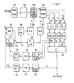
- Fig. 1 illustrates a block diagram showing the constitution of a SAR image processing system according to the present invention.
- the SAR image processing system is basically composed of; a range compression circuit 101 adapted to compress the SAR data in the range direction; a corner turning circuit 102 adapted for taking out the signals from the same region on the ground in response to a plurality of the transmitted pulses for purpose of the azimuth compression in the next step; a range curvature compensation circuit 103 for compensating the range migration; and an azimuth compression circuit 104 adapted to perform the azimuth compression using the echo signals range migration of which is compensated.
- the SAR data is divided into a real component (I) and a quadrature component (Q) so as to hold an amplitude information and a phase information, and that it is treated as complex number data and the complex signal processing is performed in each of the processings unless particularly noticed.
- the range compression-circuit 101 is of a correlator to correlate the echo signal with a conjugate function signal of the transmitted pulse signal.
- An input signal to the range compression circuit 101 comprised digital SAR data which is obtained by sampling the received signals at a predetermined period. Each of thus sampled data . represents the echo signal from the region corresponding to the range bin.
- N the total number of range bins
- N the number of azimuthal directions to be taken into account be N.
- the number of azimuthal directions is represented by the number of transmitted pulses sent out during the movement of the platform through the effective aperture length of the SAR.
- the SAR data S (m,n) (where m denotes the azimuthal direction number and n denotes the number designating the range bin) is input time-serially as follows and then stored in a memory as shown in Fig. 2;
- the corner turning circuit 102 takes out time-serially the SAR data of each range bin in the azimuth direction. This function can be simply achieved through the appropriate address designation for the data stored as shown in Fig. 2. Output from the corner turning circuit 102 is represented as follows;
- a signal R(n) denotes the echo signal of the n-th range bin
- a signal A(m) denotes the echo signal of the m-th azimuthal direction obtained from the respective range bins through the above corner turning.
- the echo signal from the given target is not located in the same bin because of the range migrations Therefore, it is required to take out the echo signals from the same target at all times from among the input data for the azimuth compression. This processing is performed through the range curvature compensation circuit.
- a change in distance A R(t) between the platform and a given point target on the ground at a timet is given by the following equation (1); where T 1 and T 2 denote starting and terminating times of irradiation by the transmitted beam to the given point target, F d ( ⁇ ); a Doppler frequency shift of the echo signal from the given point target, and, ⁇ ; a carrier wavelength.
- the range curvature compensation signal is determined based on ⁇ R.Since F dc can be assumed to be substantially constant, the range curvature compensation signal becomes a function depending on the Doppler frequency variation rate Fd and F dc only. As a result, accurate setting of Fd-is the key to the range curvature compensation and hence the reproduction of high-quality images.
- the azimuth compression circuit 104 carries out the azimuth compression by correlating the output from the range curvature compensation circuit 103 with the azimuth reference function which is also a function of Fd and is represented by where T 1 ⁇ t ⁇ T 2 ..
- the azimuthal-compressed data is divided into a plurality of look components.
- the correlation values between two look image signals selected from among the look components are developed.
- the Doppler frequency variation rate Fd is determined based on a relative shift amount (i.e., image shift) giving maximum correlation value.
- the relative shift amount represents the shift amount between the two look images to be correlated.
- the range curvature compensation signal and the reference function signal are determined based on F d developed from the shift amount giving maximum correlation value, thereby, permitting the optimum focusing at all times.
- initial values for those range curvature compensation signal and azimuth reference function signal are set in such a manner that an intensity value I of the azimuth-compressed data is computed for each value of Fd varying in a predetermined range and then the initial values are determined based on the Doppler frequency variation rate giving maximum I.
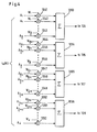
- the range curvature compensation circuit 103 comprises, as shown in Fig. 3, shift registers 1031 to 1034 of M each shift register having J stages.
- Range-compressed signals A(1), A(2), A(i), and A(M) of the 1st, the 2nd, the i-th, and the M-th azimuthal directions for the 1st to the J-th range bins are time-serially input to the 1st shift register 1031, the 2nd shift register 1032, the i-th register 1033, and the M-th register 1034, respectively.
- the stage number J of each shift register is enough to be set at a value slightly larger than the maximum value of the above-mentioned range migration, and this value can be predicted in advance.
- Data stored in the respective stages of the shift registers 1031 to 1034 are supplied to selectors 1035 to 1038 in parallel, respectively.
- the selectors 1035, 1036,..., 1037,..., 1038 selectively output signals from the stages corresponding to the range bins which are designated by compensation signals R 1 , R 21 ...,R i ,...R M supplied from a buffer memory 120 storing therein a range curvature compensation signal R.
- the range curvature compensation circuit is described in detail also in U.S. Patent No. 4,132,989.
- the transmitted beam is divided into a plurality of beams (looks), the respective looks are subjected to the compression processing independently, and then those looks are added to gain the reproduced image, whereby the reduction of the so-called speckle noise is effected.
- Division of the beam means that an area of the ground under irradiation of the beam is divided into a plurality of regions in the direction perpendicular to the traveling direction of the platform, and therefore signals from those divided regions on the ground have different center Doppler frequencies from one another. This indicates that there can be obtained separate multi-look signals by passing the azimuth-compressed signals through filters each having the center frequency predetermined for each look region and a given band width. This look is generally known and, for example, described in detail in U.S. Patent No. 4,292,634.
- Such multi-look processing is basically performed by providing a filter corresponding to a frequency characteristic of each look.
- the number of looks to be divided is set at 4 and the signals after azimuth compression are divided into four groups in the azimuth direction. More specifically, when outputs from the range curvature compensation circuit 103 are assumed to be A 1 , A 2 ,...,A i ,...,A M in accordance with respective azimuths i as shown in Fig. 3, the signal A i is multiplied by a factor W. which is determined depending on the azimuth reference function (and which is supplied from a buffer memory 121), through multipliers 1041 to 1052 thereby to carry out the azimuth compression, as shown in Fig. 4.
- the signals A i to A M are divided into four groups; A 1 to A M/4 , A M/4+1 to A M/2 , A M/2+1 to A 3M/4 , and A 3M/4+1 to A M , and then the data obtained through the azimuth compression for each divided group are added by adders 1053 to 1056. In this way, there can be obtained the range- and azimuth-compressed signal for each of 4 looks.
- an image of the target locating in the region on the ground corresponding the respective range bins in one azimuthal direction is sequentially reproduced.
- the image of N pixels in the range direction which come under irradiation of one transmitted pulse is reproduced.
- the echo signals in the range direction for the next transmission pulse are attained, the image of the next N pixels in the range direction are reproduced.
- the similar operation is repeated to reproduce the image continuously.
- the absolute values of the complex pixel signals for the respective looks are obtained by absolute value circuits 105 to 108 based on the equation of j(real component) 2 + (imaginary component)2.
- the absolute values are stored in buffer circuits 109 to 112, respectively.
- the buffer circuits 109 to 112 is to convert the time-serial data in the range direction from the azimuth compression circuit 104 into the time-serial data in the azimuth direction and hence, can be made by using the same constitution as that of the corner turning circuit 102.
- Outputs from the respective buffer circuits 109 to 112 are superimposed in an adder 113 to reduce the speckle noise and to improve the S/N ratio.
- the output of the adder 113 is fed to a display.
- Two signals among the four look processing output signals are input to a correlation coefficient calculator 114.
- L 1i and L 4i denote the compressed signals in the azimuth direction i corresponding to a certain range bin for the 1st and 4th looks, respectively.
- L 11 is written into the 1st and (M+1)th stages of the shift register 1141, L 12 ; the 2nd and (M+2)th stages thereof, and then L 1M ; the M-th and 2M-th stages thereof.
- the shift register 1141 the contents stored in the respective stages are shifted sequentially rightward by predetermined clock signals.
- the 4th look output L 4i from the buffer circuit 112 is input to the shift register 1142 having M stages in such a manner that L 41' L 42 ,..L 4M are respectively written into the 1st, 2nd,...M-th stages thereof.
- a counter 1145 counts the number of clock signals and then outputs the counted result as a shift amount (corresponding to an image shift) K.
- Outputs L 41 , L 42 ,...,L 4M from the respective stages of the shift register 1142 are supplied to multipliers 1143(1), 1143(2),..,1143(M) which are in turn connected to the respective outputs of the 1st to M-th stages of the shift register 1141.
- Outputs from the M multipliers are added by an adder 144 and then output therefrom as a correlation value R(0) at a shift of 0.
- R(0) a correlation value
- the correlation value R(K) is represented by the following equation (5) based on the 1st and 4th look outputs L 1i , L 41 ; where L 1i,(i+K) denotes output from the (i+K)-th stage of the shift register 1141.
- Fig. 5B illustrates conceptually the correlation processing between the contents stored in the respective stages of both shift registers 1141 and 1142.
- the first term of the equation (5) represents the correlation in the X portion of Fig. 5B, while the second term represents the correlation in the Y portion thereof.
- the correlation coefficient value R(K) at a shift of K thus obtained by the correlation coefficient calculator 114 is stored in a buffer memory 115.
- a maximum value detecting circuit 116 detects the shift K giving the maximum correlation coefficient value among the data stored in the buffer memory 115 and then supply K to a Doppler frequency variation rate (F d ) compensator 117.
- the shift K at the maximum value of R(K) represents an image shift between both look images. Accordingly, the absence of image shift corresponds to that the correlation factor R(0) assumes the maximum value. Image shift will be caused by improperly setting of the range curvature compensation signal and the azimuth compression reference function signal.
- both range bin selection signal in the range curvature compensation circuit and the azimuth reference function signal are determined based on the image shift K, and then thus determined signals are used to again carry out the range curvature compensation and the azimuth compression. Such a processing is repeated through a feedback loop until the image shift becomes 0.
- Fig. 6 shows a relationship between the Doppler frequency f d of the received signal from a point target on the ground and a time. It is assumed that t is 0 when the platform traveling along a circular orbit is positioned just beside the above point target.
- ⁇ is a linear line whose inclination represents the Doppler frequency variation rate dR of the actually received signal
- ⁇ is a linear line whose inclination represents the Doppler frequency variation rate F d used for the range curvature compensation and the azimuth compression.
- times t and t B at points A and B-at which a horizontal dot line passing through f 4c intersects with the linear lines of ⁇ and ⁇ , respectively indicate the time point where an image appears through the processing based on F dR and the time point where an image appears through the current image processing based on F d used therefor.
- a difference (assumed to be d/2) between both time points t A and t B appears a shift on the reproduced image.
- a difference (equal to d/2) between the time points t c and t D corresponding to points C and D at which a horizontal line passing through f 1c intersects with the linear lines of ⁇ and ⁇ , respectively also appears a shift on the reproduced image.
- the actual Doppler frequency variation rate F dR can be expressed by the equation (8) as follows;
- an compensation amount ⁇ dR of the Doppler frequency variation rate can be expressed as follows;
- the image shift d in the above equations corresponds to the shit ammount K when the aforesaid correlation coefficient R(K) is the maximum value, so that it is possible to attain the well-focused reproduced images by newly setting the Doppler frequency variation rate F d based on the equation (8) in accordance with the resulted shift amount K.
- the determination of the range curvature compensation signal and the azimuth reference function signal based on improper setting of F d makes obscured images and makes it difficult to gain the accurate shift amount, it is impossible to obtain the accurate Doppler frequency variation rate F d immediately from the equation (8).
- the Doppler frequency variation rate is newly set based on the equation (8) corresponding to the value of the image shift K.
- the Doppler frequency variation rate (F d ) compensator 117 outputs the Doppler frequency variation rate F d to be newly set to an azimuth reference function signal fenerator 118 and a range curvature comsation signal generator 119 based on the equation (8) corresponding to the shift amount K which is obtained from the maximum value detecting circuit 116.
- the azimuth reference function generator 118 determines the azimuth reference function using the aforesaid equation (4) in response to F d , and then stores a factor W. for each azimuth direction i into the buffer memory 121.
- the buffer memory 121 there is stored thus determined factor W i for the azimuth compression, and the respective factors W 1 , W 2 ,..,W M used in the azimuth compression circuit shown in Fig. 4 are output to the multipliers 1041, 1042,..,1052.
- the range curvature compensation signal i.e. range bin selection signal
- R i the range curvature compensation signal
- the approximate Doppler frequency variation rate F d0 is first preset based on parameters such as speed, altitude and attitute of the platform.
- the intensity of the signal of the look output or the signal obtained by adding look outputs is attained through the determination of the variance value for each Doppler .
- frequency variation rate varying in a predetermined range about d0 and the Doppler frequency variation rate giving maximum variance value is set as the new initial value.
- the above-mentioned auto-focusing processing according to the present invention is carried out repeatedly while finely adjusting the Doppler frequency variation rate based on the resulted image shift K.
- the intensity is computed by an intensity calculating circuit 122 using one of outputs from the absolute value circuits 105 to 108 or a synthetic (i.e., superimposed) output signal of two or more outputs.
- the intensity calculating circuit 122 computes the intensity I which is defined by the variance value, using the following equation (10); where Li is an amplitude value of the respective data L i and L i is a mean value of M data L 1 to L M . The larger the intensity becomes, the stronger the contrast becomes. More concretely, the intensity circuit 122 obtains a value of the intensity I for each Dopper frequency variation rate and then stores the intensity I into a buffer memory 123 with a value of corresponding Dopper frequency variation rate.
- a maximum value detecting circuit 124 detects the maximum value of intensities being stored in the buffer memory 123, and selects the corresponding Doppler frequency variation rate F dO as the best value at that time to send it to a buffer memory 125.
- the buffer memory 125 sends out an initial setting signal d0 to the R i generator 119 and the W i generator 118 in its initial state. But after receiving d0 from the maximum value detecting circuit 124, the buffer memory 125 supplies d0 to both signal generators 118 and 119.
- These signal generators 118 and 119 generate the range curvature compensation signal and the azimuth reference function signal based on the supplied Doppler frequency variation rate, respectively, as previously stated.
- output of the F d compensator 117 is fed to both signal generators 118 and 119 upon changing-over of a switch 126, and then the above-mentioned auto-focusing is performed.
- processing for the range compression and azimuth compression is possible not only in a time domain but also in frequency domain.
- an arithmetic processing velocity can be significantly in the latter processing.
Applications Claiming Priority (4)
| Application Number | Priority Date | Filing Date | Title |
|---|---|---|---|
| JP210344/81 | 1981-12-28 | ||
| JP210343/81 | 1981-12-28 | ||
| JP56210344A JPS58113877A (ja) | 1981-12-28 | 1981-12-28 | 合成開口レ−ダオ−トフオ−カス画像処理装置 |
| JP56210343A JPS58113876A (ja) | 1981-12-28 | 1981-12-28 | 合成開口レ−ダオ−トフオ−カス画像処理装置 |
Publications (3)
| Publication Number | Publication Date |
|---|---|
| EP0083107A2 true EP0083107A2 (de) | 1983-07-06 |
| EP0083107A3 EP0083107A3 (en) | 1984-07-25 |
| EP0083107B1 EP0083107B1 (de) | 1989-03-29 |
Family
ID=26517999
Family Applications (1)
| Application Number | Title | Priority Date | Filing Date |
|---|---|---|---|
| EP82112066A Expired EP0083107B1 (de) | 1981-12-28 | 1982-12-28 | Bildverarbeitungsanlage mit synthetischer Apertur |
Country Status (4)
| Country | Link |
|---|---|
| US (1) | US4594593A (de) |
| EP (1) | EP0083107B1 (de) |
| CA (1) | CA1203871A (de) |
| DE (1) | DE3279581D1 (de) |
Cited By (10)
| Publication number | Priority date | Publication date | Assignee | Title |
|---|---|---|---|---|
| EP0131907A1 (de) * | 1983-07-15 | 1985-01-23 | Hitachi, Ltd. | Verfahren zur Erzeugung des Bildes bei einem Radar mit synthetischer Apertur |
| EP0227614A2 (de) * | 1985-12-24 | 1987-07-01 | SELENIA INDUSTRIE ELETTRONICHE ASSOCIATE S.p.A. | Signalverarbeitungsvorrichtung für Radar mit synthetischer Apertur, insbesondere geeignet für Parallelberechnung |
| DE3644363A1 (de) * | 1985-12-27 | 1987-07-02 | Mitsubishi Electric Corp | System zum abbilden eines objektes mit ultraschall- oder elektromagnetischen wellen |
| EP0449303A2 (de) * | 1990-03-29 | 1991-10-02 | Hughes Aircraft Company | Phasendifferenz-Autofokus-Einstellung zur Bilderzeugung bei einem Radar mit synthetischer Apertur |
| DE4037725A1 (de) * | 1990-11-27 | 1992-06-11 | Deutsche Forsch Luft Raumfahrt | Verfahren zur digitalen generierung von sar-bildern und einrichtung zu dessen durchfuehrung |
| GB2258111A (en) * | 1991-07-19 | 1993-01-27 | Deutsche Forsch Luft Raumfahrt | Determining phase errors caused by the atmosphere in a coherent radar. |
| GB2258361A (en) * | 1985-07-02 | 1993-02-03 | Gec Avionics | A synthetic aperture radar |
| EP0545778A1 (de) * | 1991-11-29 | 1993-06-09 | Fujitsu Limited | Ultraschall-Diagnosengerät mit synthetischer Apparatur |
| EP0602473A1 (de) * | 1992-12-16 | 1994-06-22 | Daimler-Benz Aerospace Aktiengesellschaft | Radargerät mit synthetischer Apertur auf der Basis rotierender Antennen |
| EP2256515A4 (de) * | 2008-03-07 | 2015-05-06 | Japan Agency Marine Earth Sci | System und verfahren zur verarbeitung der synthetischen apertur |
Families Citing this family (21)
| Publication number | Priority date | Publication date | Assignee | Title |
|---|---|---|---|---|
| WO1986006177A1 (en) * | 1985-04-08 | 1986-10-23 | Hughes Aircraft Company | High speed synthetic aperture radar processing system |
| US4780718A (en) * | 1985-06-17 | 1988-10-25 | Hughes Aircraft Company | Sar image encoding for data compression |
| DE3688528T2 (de) * | 1986-01-22 | 1994-01-13 | Hughes Aircraft Co | Optische analoge datenverarbeitungsanordnungen zur behandlung von bipolaren und komplexen daten. |
| GB8630315D0 (en) * | 1986-12-18 | 1987-04-15 | Gen Electric Co Plc | Synthetic aperture radar |
| JPS63222286A (ja) * | 1987-03-11 | 1988-09-16 | Tokyo Electric Power Co Inc:The | 地中埋設物探査方式 |
| GB8719395D0 (en) * | 1987-08-17 | 1988-04-27 | Gen Electric Co Plc | Radar systems |
| US4829303A (en) * | 1988-05-18 | 1989-05-09 | The United States Of America As Represented By The Administrator Of The National Aeronautics And Space Administration | Data volume reduction for imaging radar polarimetry |
| US5021789A (en) * | 1990-07-02 | 1991-06-04 | The United States Of America As Represented By The Secretary Of The Air Force | Real-time high resolution autofocus system in digital radar signal processors |
| GB2279196B (en) * | 1990-10-29 | 1995-05-17 | Marconi Gec Ltd | Processing means for radar system |
| DE4122592C1 (de) * | 1991-07-08 | 1993-01-28 | Deutsche Forschungsanstalt Fuer Luft- Und Raumfahrt Ev, 5300 Bonn, De | |
| US5736957A (en) * | 1995-06-30 | 1998-04-07 | The Johns Hopkins University | Delay compensated doppler radar altimeter |
| CA2265448C (en) * | 1996-09-30 | 2006-01-10 | The Johns Hopkins University | Delay compensated doppler radar altimeter |
| US7106250B2 (en) * | 2003-09-03 | 2006-09-12 | The United States Of America As Represented By The Secretary Of The Navy | Robust predictive deconvolution system and method |
| US8576111B2 (en) * | 2009-02-23 | 2013-11-05 | Imsar Llc | Synthetic aperture radar system and methods |
| DE102009030076A1 (de) * | 2009-06-23 | 2010-12-30 | Symeo Gmbh | Abbildungsverfahren mittels synthetischer Apertur, Verfahren zur Bestimmung einer Relativgeschwindigkeit zwischen einem wellenbasierten Sensor und einem Objekt bzw. Vorrichtung zur Durchführung der Verfahren |
| CN104614725B (zh) * | 2015-01-21 | 2017-05-17 | 中国科学院电子学研究所 | 一种扫描合成孔径雷达图像质量提升方法和装置 |
| CN105676190B (zh) * | 2015-12-31 | 2018-07-24 | 中国科学院电子学研究所 | 一种校正合成孔径雷达回波数据的方法和装置 |
| WO2019123786A1 (ja) * | 2017-12-18 | 2019-06-27 | 日本電気株式会社 | 合成開口レーダの信号処理装置及び信号処理方法 |
| US10677915B2 (en) | 2018-02-07 | 2020-06-09 | Mitsubishi Electric Research Laboratories, Inc. | System and method for fused radar imaging under position ambiguity of antennas |
| JP7151876B2 (ja) * | 2019-03-29 | 2022-10-12 | 日本電気株式会社 | 合成開口レーダの画像処理装置及び画像処理方法 |
| KR20210106864A (ko) * | 2020-02-20 | 2021-08-31 | 삼성전자주식회사 | 레이더 신호에 기초한 오브젝트 검출 방법 및 장치 |
Citations (2)
| Publication number | Priority date | Publication date | Assignee | Title |
|---|---|---|---|---|
| US4132989A (en) * | 1977-10-18 | 1979-01-02 | Nasa | Azimuth correlator for real-time synthetic aperture radar image processing |
| US4292634A (en) * | 1978-12-15 | 1981-09-29 | Nasa | Real-time multiple-look synthetic aperture radar processor for spacecraft applications |
Family Cites Families (6)
| Publication number | Priority date | Publication date | Assignee | Title |
|---|---|---|---|---|
| US4163231A (en) * | 1968-01-03 | 1979-07-31 | Raytheon Company | Radar mapping technique |
| US4034370A (en) * | 1972-08-23 | 1977-07-05 | Westinghouse Electric Corporation | Second order motion compensator for high resolution radar |
| GB1471888A (en) * | 1973-06-07 | 1977-04-27 | Emi Ltd | Synthetic aperture radar |
| US4219811A (en) * | 1975-02-07 | 1980-08-26 | Hughes Aircraft Company | Synthetic array autofocus system |
| US4045795A (en) * | 1975-06-23 | 1977-08-30 | Nasa | Charge-coupled device data processor for an airborne imaging radar system |
| US4471357A (en) * | 1981-10-26 | 1984-09-11 | The United States Of America As Represented By The Administrator Of The National Aeronautics And Space Administration | Pipelined digital SAR azimuth correlator using hybrid FFT/transversal filter |
-
1982
- 1982-12-28 DE DE8282112066T patent/DE3279581D1/de not_active Expired
- 1982-12-28 US US06/454,139 patent/US4594593A/en not_active Expired - Lifetime
- 1982-12-28 EP EP82112066A patent/EP0083107B1/de not_active Expired
- 1982-12-29 CA CA000418702A patent/CA1203871A/en not_active Expired
Patent Citations (2)
| Publication number | Priority date | Publication date | Assignee | Title |
|---|---|---|---|---|
| US4132989A (en) * | 1977-10-18 | 1979-01-02 | Nasa | Azimuth correlator for real-time synthetic aperture radar image processing |
| US4292634A (en) * | 1978-12-15 | 1981-09-29 | Nasa | Real-time multiple-look synthetic aperture radar processor for spacecraft applications |
Non-Patent Citations (4)
| Title |
|---|
| PROCEEDINGS OF THE 3RD SEASAT-SAR WORKSHOP ON "SAR IMAGE QUALITY" Held at Frascati (IT), 11th-12th December 1980, ESASP-172, pages 19-22; * |
| PROCEEDINGS OF THE I.E.E.-F, vol. 127, no. 2, April 1980, pages 155-162, Stevenage (GB); * |
| PROCEEDINGS OF THE IEEE, vol. 70, no. 10, October 1982, pages 1174-1209, New York (USA); * |
| THE MARCONI REVIEW, vol. 60, no. 225, Second Quarter 1982, pages 84-105, Rugby (GB); * |
Cited By (19)
| Publication number | Priority date | Publication date | Assignee | Title |
|---|---|---|---|---|
| EP0131907A1 (de) * | 1983-07-15 | 1985-01-23 | Hitachi, Ltd. | Verfahren zur Erzeugung des Bildes bei einem Radar mit synthetischer Apertur |
| GB2258361A (en) * | 1985-07-02 | 1993-02-03 | Gec Avionics | A synthetic aperture radar |
| GB2258361B (en) * | 1985-07-02 | 1993-07-14 | Gec Avionics | A synthetic aperture radar |
| EP0227614A2 (de) * | 1985-12-24 | 1987-07-01 | SELENIA INDUSTRIE ELETTRONICHE ASSOCIATE S.p.A. | Signalverarbeitungsvorrichtung für Radar mit synthetischer Apertur, insbesondere geeignet für Parallelberechnung |
| EP0227614A3 (de) * | 1985-12-24 | 1989-06-14 | SELENIA INDUSTRIE ELETTRONICHE ASSOCIATE S.p.A. | Signalverarbeitungsvorrichtung für Radar mit synthetischer Apertur, insbesondere geeignet für Parallelberechnung |
| DE3644363A1 (de) * | 1985-12-27 | 1987-07-02 | Mitsubishi Electric Corp | System zum abbilden eines objektes mit ultraschall- oder elektromagnetischen wellen |
| EP0449303A2 (de) * | 1990-03-29 | 1991-10-02 | Hughes Aircraft Company | Phasendifferenz-Autofokus-Einstellung zur Bilderzeugung bei einem Radar mit synthetischer Apertur |
| AU638558B2 (en) * | 1990-03-29 | 1993-07-01 | Hughes Aircraft Company | Phase difference auto focusing for synthetic aperture radar imaging |
| EP0449303A3 (en) * | 1990-03-29 | 1993-08-11 | Hughes Aircraft Company | Phase difference auto focusing for synthetic aperture radar imaging |
| US5191344A (en) * | 1990-11-27 | 1993-03-02 | Deutsche Forschungsanstalt Fur Luft- Und Raumfahrt | Method for digital generation of sar images and apparatus for carrying out said method |
| DE4037725A1 (de) * | 1990-11-27 | 1992-06-11 | Deutsche Forsch Luft Raumfahrt | Verfahren zur digitalen generierung von sar-bildern und einrichtung zu dessen durchfuehrung |
| GB2258111A (en) * | 1991-07-19 | 1993-01-27 | Deutsche Forsch Luft Raumfahrt | Determining phase errors caused by the atmosphere in a coherent radar. |
| FR2682773A1 (fr) * | 1991-07-19 | 1993-04-23 | Deutsche Forsch Luft Raumfahrt | Procede et dispositif d'extraction d'erreurs de phase occasionnees par l'atmosphere dans le signal de retrodiffusion d'un systeme d'imagerie radar coherent. |
| US5257028A (en) * | 1991-07-19 | 1993-10-26 | Deutsche Forschungsanstalt Fur Luft- Und Raumfahrt E.V. | Method of extracting phase errors caused by the atmosphere in the backscatter signal of a coherent imaging radar system carried by a carrier from radar raw data and apparatus for carrying out the method |
| GB2258111B (en) * | 1991-07-19 | 1995-01-11 | Deutsche Forsch Luft Raumfahrt | Method of extracting phase errors caused by the atmosphere in the back-scatter signal of a coherent imaging radar system |
| EP0545778A1 (de) * | 1991-11-29 | 1993-06-09 | Fujitsu Limited | Ultraschall-Diagnosengerät mit synthetischer Apparatur |
| US5299576A (en) * | 1991-11-29 | 1994-04-05 | Fujitsu Limited | Ultrasonic synthetic aperture diagnostic apparatus |
| EP0602473A1 (de) * | 1992-12-16 | 1994-06-22 | Daimler-Benz Aerospace Aktiengesellschaft | Radargerät mit synthetischer Apertur auf der Basis rotierender Antennen |
| EP2256515A4 (de) * | 2008-03-07 | 2015-05-06 | Japan Agency Marine Earth Sci | System und verfahren zur verarbeitung der synthetischen apertur |
Also Published As
| Publication number | Publication date |
|---|---|
| EP0083107A3 (en) | 1984-07-25 |
| DE3279581D1 (en) | 1989-05-03 |
| CA1203871A (en) | 1986-04-29 |
| EP0083107B1 (de) | 1989-03-29 |
| US4594593A (en) | 1986-06-10 |
Similar Documents
| Publication | Publication Date | Title |
|---|---|---|
| EP0083107A2 (de) | Bildverarbeitungsanlage mit synthetischer Apertur | |
| US4084158A (en) | Method of operating synthetic aperture radar | |
| US4134113A (en) | Monopulse motion compensation for a synthetic aperture radar | |
| US4034370A (en) | Second order motion compensator for high resolution radar | |
| US5708436A (en) | Multi-mode radar system having real-time ultra high resolution synthetic aperture radar (SAR) capability | |
| US5608404A (en) | Imaging synthetic aperture radar | |
| EP0298112B1 (de) | Verarbeitungsparameter-generator für radar mit synthetischer apertur | |
| EP0239022A2 (de) | Verbesserte Darstellung bei einem Radar mit synthetischer Apertur zur Schiffsklassifizierung | |
| RU2168741C2 (ru) | Устройство для компенсации погрешностей движения для рлс с синтезированной апертурой на основе вращающихся антенн (rosar) для вертолетов | |
| US4292634A (en) | Real-time multiple-look synthetic aperture radar processor for spacecraft applications | |
| EP0344272B1 (de) | Unterdrückung von azimutaler mehrdeutigkeit im sar-signal | |
| US5016018A (en) | Aperture synthesized radiometer using digital beamforming techniques | |
| US5512899A (en) | Method of evaluating the image quality of a synthetic aperture radar | |
| US7218272B2 (en) | Reducing antenna boresight error | |
| US6204799B1 (en) | Three dimensional bistatic imaging radar processing for independent transmitter and receiver flightpaths | |
| EP0110260B1 (de) | Pulsradargerät | |
| US5334980A (en) | Method and system for sharpening impulse response in a synthetic aperture radar | |
| US4339752A (en) | Synthetic array processor | |
| US4246580A (en) | Image processing for bistatic image radar | |
| US4644356A (en) | Bistatic coherent radar receiving system | |
| US3121868A (en) | High resolution object location system | |
| US4706089A (en) | Synthetic aperture radar focusing | |
| Shuchman et al. | Processing of ocean wave data from a synthetic aperture radar | |
| US4706088A (en) | Synthetic aperture radar focusing | |
| US4564839A (en) | Feature referenced error correction apparatus |
Legal Events
| Date | Code | Title | Description |
|---|---|---|---|
| PUAI | Public reference made under article 153(3) epc to a published international application that has entered the european phase |
Free format text: ORIGINAL CODE: 0009012 |
|
| AK | Designated contracting states |
Designated state(s): BE DE FR GB IT NL |
|
| RAP1 | Party data changed (applicant data changed or rights of an application transferred) |
Owner name: NEC CORPORATION |
|
| PUAL | Search report despatched |
Free format text: ORIGINAL CODE: 0009013 |
|
| AK | Designated contracting states |
Designated state(s): BE DE FR GB IT NL |
|
| 17P | Request for examination filed |
Effective date: 19840817 |
|
| 17Q | First examination report despatched |
Effective date: 19860319 |
|
| GRAA | (expected) grant |
Free format text: ORIGINAL CODE: 0009210 |
|
| AK | Designated contracting states |
Kind code of ref document: B1 Designated state(s): BE DE FR GB IT NL |
|
| REF | Corresponds to: |
Ref document number: 3279581 Country of ref document: DE Date of ref document: 19890503 |
|
| ET | Fr: translation filed | ||
| ITF | It: translation for a ep patent filed |
Owner name: MODIANO & ASSOCIATI S.R.L. |
|
| PLBE | No opposition filed within time limit |
Free format text: ORIGINAL CODE: 0009261 |
|
| STAA | Information on the status of an ep patent application or granted ep patent |
Free format text: STATUS: NO OPPOSITION FILED WITHIN TIME LIMIT |
|
| 26N | No opposition filed | ||
| ITTA | It: last paid annual fee | ||
| PGFP | Annual fee paid to national office [announced via postgrant information from national office to epo] |
Ref country code: BE Payment date: 19991122 Year of fee payment: 18 |
|
| PGFP | Annual fee paid to national office [announced via postgrant information from national office to epo] |
Ref country code: FR Payment date: 19991208 Year of fee payment: 18 |
|
| PGFP | Annual fee paid to national office [announced via postgrant information from national office to epo] |
Ref country code: GB Payment date: 19991222 Year of fee payment: 18 |
|
| PGFP | Annual fee paid to national office [announced via postgrant information from national office to epo] |
Ref country code: NL Payment date: 19991228 Year of fee payment: 18 |
|
| PGFP | Annual fee paid to national office [announced via postgrant information from national office to epo] |
Ref country code: DE Payment date: 19991231 Year of fee payment: 18 |
|
| PG25 | Lapsed in a contracting state [announced via postgrant information from national office to epo] |
Ref country code: GB Free format text: LAPSE BECAUSE OF NON-PAYMENT OF DUE FEES Effective date: 20001228 |
|
| PG25 | Lapsed in a contracting state [announced via postgrant information from national office to epo] |
Ref country code: BE Free format text: LAPSE BECAUSE OF NON-PAYMENT OF DUE FEES Effective date: 20001231 |
|
| BERE | Be: lapsed |
Owner name: NEC CORP. Effective date: 20001231 |
|
| PG25 | Lapsed in a contracting state [announced via postgrant information from national office to epo] |
Ref country code: NL Free format text: LAPSE BECAUSE OF NON-PAYMENT OF DUE FEES Effective date: 20010701 |
|
| GBPC | Gb: european patent ceased through non-payment of renewal fee |
Effective date: 20001228 |
|
| PG25 | Lapsed in a contracting state [announced via postgrant information from national office to epo] |
Ref country code: FR Free format text: LAPSE BECAUSE OF NON-PAYMENT OF DUE FEES Effective date: 20010831 |
|
| NLV4 | Nl: lapsed or anulled due to non-payment of the annual fee |
Effective date: 20010701 |
|
| REG | Reference to a national code |
Ref country code: FR Ref legal event code: ST |
|
| PG25 | Lapsed in a contracting state [announced via postgrant information from national office to epo] |
Ref country code: DE Free format text: LAPSE BECAUSE OF NON-PAYMENT OF DUE FEES Effective date: 20011002 |