EP0082947B1 - Rotating vacuum or pressure powered feeding and discharging lock - Google Patents
Rotating vacuum or pressure powered feeding and discharging lock Download PDFInfo
- Publication number
- EP0082947B1 EP0082947B1 EP82110553A EP82110553A EP0082947B1 EP 0082947 B1 EP0082947 B1 EP 0082947B1 EP 82110553 A EP82110553 A EP 82110553A EP 82110553 A EP82110553 A EP 82110553A EP 0082947 B1 EP0082947 B1 EP 0082947B1
- Authority
- EP
- European Patent Office
- Prior art keywords
- rotor
- feeding
- housing
- discharging
- wall
- Prior art date
- Legal status (The legal status is an assumption and is not a legal conclusion. Google has not performed a legal analysis and makes no representation as to the accuracy of the status listed.)
- Expired
Links
Images

Classifications
-
- F—MECHANICAL ENGINEERING; LIGHTING; HEATING; WEAPONS; BLASTING
- F26—DRYING
- F26B—DRYING SOLID MATERIALS OR OBJECTS BY REMOVING LIQUID THEREFROM
- F26B25/00—Details of general application not covered by group F26B21/00 or F26B23/00
- F26B25/001—Handling, e.g. loading or unloading arrangements
- F26B25/002—Handling, e.g. loading or unloading arrangements for bulk goods
-
- B—PERFORMING OPERATIONS; TRANSPORTING
- B65—CONVEYING; PACKING; STORING; HANDLING THIN OR FILAMENTARY MATERIAL
- B65G—TRANSPORT OR STORAGE DEVICES, e.g. CONVEYORS FOR LOADING OR TIPPING, SHOP CONVEYOR SYSTEMS OR PNEUMATIC TUBE CONVEYORS
- B65G53/00—Conveying materials in bulk through troughs, pipes or tubes by floating the materials or by flow of gas, liquid or foam
- B65G53/34—Details
- B65G53/40—Feeding or discharging devices
- B65G53/46—Gates or sluices, e.g. rotary wheels
- B65G53/4608—Turnable elements, e.g. rotary wheels with pockets or passages for material
- B65G53/4625—Turnable elements, e.g. rotary wheels with pockets or passages for material with axis of turning perpendicular to flow
- B65G53/4633—Turnable elements, e.g. rotary wheels with pockets or passages for material with axis of turning perpendicular to flow the element having pockets, rotated from charging position to discharging position, i.e. discrete flow
-
- G—PHYSICS
- G01—MEASURING; TESTING
- G01F—MEASURING VOLUME, VOLUME FLOW, MASS FLOW OR LIQUID LEVEL; METERING BY VOLUME
- G01F11/00—Apparatus requiring external operation adapted at each repeated and identical operation to measure and separate a predetermined volume of fluid or fluent solid material from a supply or container, without regard to weight, and to deliver it
- G01F11/10—Apparatus requiring external operation adapted at each repeated and identical operation to measure and separate a predetermined volume of fluid or fluent solid material from a supply or container, without regard to weight, and to deliver it with measuring chambers moved during operation
- G01F11/12—Apparatus requiring external operation adapted at each repeated and identical operation to measure and separate a predetermined volume of fluid or fluent solid material from a supply or container, without regard to weight, and to deliver it with measuring chambers moved during operation of the valve type, i.e. the separating being effected by fluid-tight or powder-tight movements
- G01F11/20—Apparatus requiring external operation adapted at each repeated and identical operation to measure and separate a predetermined volume of fluid or fluent solid material from a supply or container, without regard to weight, and to deliver it with measuring chambers moved during operation of the valve type, i.e. the separating being effected by fluid-tight or powder-tight movements wherein the measuring chamber rotates or oscillates
- G01F11/24—Apparatus requiring external operation adapted at each repeated and identical operation to measure and separate a predetermined volume of fluid or fluent solid material from a supply or container, without regard to weight, and to deliver it with measuring chambers moved during operation of the valve type, i.e. the separating being effected by fluid-tight or powder-tight movements wherein the measuring chamber rotates or oscillates for fluent solid material
Definitions
- the invention relates, according to the preamble of claim 1, to a loading and emptying device for bulk goods with at least one rotor which can be rotated in a housing between the inlet nozzle and the emptying nozzle and a chamber arranged around the axis of rotation, in the wall of which an unlocked opening serving for filling and emptying is, in which in the upper part of the housing a feed nozzle and in the lower part an emptying nozzle are arranged, particularly suitable for metering and filling systems for bulk materials such as gravel, crushed stone, sand and the like.
- Feeding and emptying devices enable bulk materials to be conveyed to different rooms with low pressure differences without gas closure, depending on the resistance of the porous, gas- and air-permeable bulk material to be sluiced.
- a disadvantage of such locks is that the bulk material is continuously circulated during conveyance, emerges from the unlocked cell opening and passes over the housing inner wall to be discharged.
- bulk solids inevitably come into the gap between the outer rotor wall and the inner wall of the housing, where the good particles are ground and lead to rapid wear of the lock parts in contact with the product or block the rotor.
- the housing wall is designed to be movable.
- Another disadvantage here is that the clamped material can cause the movable housing wall to be lifted off undesirably, which creates a gap through which the bulk material can fall past the rotor and an atmosphere exchange through the gap is made possible.
- German patent DE-AS-2 111 434 attempts are made to prevent the jamming of good particles.
- the rotor is particularly at risk from blockage, since when the cell opening moves upwards, material which has already been filled in is clamped into the wedge gap that is becoming smaller.
- French patent FR-A-1 142 126 in which, however, the rubber wiper provided for the falling of bulk material into the gap is additionally destroyed by material from the upwardly opening cell opening.
- This lock is suitable for locking approx. Max. 14 m 3 / h at a vacuum of 25 mbar abs. It is very complex, destroys the grain, is prone to wear and is very expensive.
- a vacuum or pressure lock with a low leakage air rate for all vacuum areas, pressure areas and bulk materials which are characterized by a special rotor cavity construction in connection with high rotor acceleration or rotor deceleration and metered part quantity
- Unclosed rotor cavity does not allow bulk material to come out of the cavity between the rotor and housing during rotation and thus enables the use of sliding seals as an atmospheric seal in which the material falls out due to its own weight or is thrown out by an air or gas layer expanding around the material.
- the high rotor frequencies allow minimal housing dimensions and the largest possible bulk quantities can be sluiced, the whole can be economically manufactured in accordance with the previous issue and simple structure.
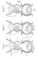
- FIGS. 1, 2 and 3 A special embodiment is solved in the characterizing part of claim 2, which are shown in FIGS. 1, 2 and 3.
- the rotor cavity floor has a spiral or spiral-like shape.
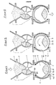
- FIGS. 4, 5 and 6 show.
- a centrally arranged segment 15a is attached to the rotor inner wall 15 opposite the rotor filling opening via a connecting piece 17.
- only one seal is used, which surrounds the rotor casing from the filler neck to the drain neck.
- the rotor opening is reduced on one side by the amount 6a (FIG. 4), so that the radian measure is extended from the sealing edge 14a to the rotor opening edge 6b, as a result of which the pressure compensation in the interior of the rotor is delayed.
- the rotor is multi-stage, the cells being connected to one another in a specific position, as a result of which the atmosphere escapes from the cell with the higher pressure into the other cell with the lower pressure. This significantly reduces the scooping air.
- the housing inlet connection, housing outlet connection and rotor cavity are suctioned off.
- FIGS. 7, 8 and 9 Another embodiment of the rotor interior is solved in the characterizing part of claim 8, which is shown in FIGS. 7, 8 and 9. This design forces moist, slightly sticky material to remain in its filling position while the rotor is rotating.
- the advantages achieved by the invention consist in the fact that a lock was created which can also be used under 25 mbar up to the fine vacuum range and a pressure lock which can be used over 3 bar up to the high pressure range, while having leakage air rates as low as is customary in fittings with these seals , much larger quantities than 14 m 3 / h without additional auxiliary devices for closing the rotor opening and forced clearing of the goods, can be handled gently, makes space-saving planning possible for new systems due to the small dimensions and therefore can also be used to convert existing systems and economical production guaranteed.
- FIG. 1 shows the position of the vacuum lock after filling
- FIG. 2 the position of the rotor when the cell enters the other atmosphere
- FIG. 3 the position of the rotor before emptying. The movement of the bulk material during the rotation of the rotor was not taken into account for better understanding and for easier illustration.
- a certain part of the dried material 2, 10 is put into the cell 5 of the stationary rotor 6 by means of the cell wheel 3.
- the pneumatically driven rotor 6 of the vacuum lock is rotated by approximately 180 degrees in less than 0.1 seconds, the bulk material 10 falls out due to its own weight with the support of the gas expanding around the material.
- the rotor 6 rotates in the starting position according to FIG. 1 and the process begins again.
- the vacuum of the dryer is also present via the connecting line 13 at the outlet of the cellular wheel sluice or in cell 5 of the vacuum sluice, so that the cellular wheel 3 operates at the same pressures.
- the returned air from the cell 5 escapes through the connecting pipe 13 into the dryer.
- the entire vacuum in the cell 5 breaks down because, according to the invention, the gap 16 has formed between the cell wall 15 and the filled bulk material 10 during the rotation.
- the gap thickness results from the speed of the rotor 6 and the free fall of the bulk material 10.
- the gap thickness is chosen so that the material cannot rest on the cell wall 15 and / or the seal 14 during the rotation.
Description
Die Erfindung bezieht sich gemäß dem Oberbegriff des Anspruchs 1 auf eine Beschickungs-und Entleerungseinrichtung für Schüttgüter mit mindestens einen, in einem Gehäuse zwischen Einlaufstutzen und Entleerungsstutzen drehbaren Rotor und um die Drehachse angeordneter Kammer, in deren Wand eine zum Füllen und Entleeren dienende, unverschlossene Öffnung ist, bei dem im Oberteil des Gehäuses ein Beschickungsstutzen und im Unterteil ein Entleerungsstutzen angeordnet sind, insbesondere geeignet für Dosier- und Abfüllanlagen von Schüttgütern wie Kies, Schotter, Sand und dergleichen.The invention relates, according to the preamble of claim 1, to a loading and emptying device for bulk goods with at least one rotor which can be rotated in a housing between the inlet nozzle and the emptying nozzle and a chamber arranged around the axis of rotation, in the wall of which an unlocked opening serving for filling and emptying is, in which in the upper part of the housing a feed nozzle and in the lower part an emptying nozzle are arranged, particularly suitable for metering and filling systems for bulk materials such as gravel, crushed stone, sand and the like.
Beschickungs- und Entleerungseinrichtungen ermöglichen die Förderung von Schüttgütern in unterschiedliche Räume mit geringen Druckunterschieden ohne Gasabschluß entsprechend dem Widerstand des zu schleusenden porösen, gas- und luftdurchlässigen Schüttgutes.Feeding and emptying devices enable bulk materials to be conveyed to different rooms with low pressure differences without gas closure, depending on the resistance of the porous, gas- and air-permeable bulk material to be sluiced.
Es sind folgende Beschickungs- und Entleerungseinrichtungen bekannt, nämlich
- FR-A-1 142126
- FR-A-1 246 446
- DE-B1-2 918 786
- DE-AS-2111434
- DE-GM-1 920 200,
bei denen die Zellen der langsamdrehenden Rotoren über eine, durch das Eigengewicht selbsttätig nachfließenden, auf den Rotor abgestützten Schüttgutsäule gefüllt werden. Der Füllvorgang der leeren Zelle beginnt bereits bei der Aufwärtsbewegung der Zellenöffnung und zwar dann, wenn die vordere Innenkante der Zellenöffnung in Drehrichtung den Einfüllstutzen erreicht hat. Die Trennung des in die Zelle eingefüllten Gutes von der sich darauf abstützenden Produktsäule erfolgt durch die hintere Innenkante der Zellenöffnung in Drehrichtung, in dem sie die Säule durchschneidet.The following loading and emptying devices are known, namely:
- FR-A-1 142126
- FR-A-1 246 446
- DE-B1-2 918 786
- DE-AS-2111434
- DE-GM-1 920 200,
in which the cells of the slowly rotating rotors are filled via a bulk material column supported by the rotor, which flows automatically due to its own weight. The filling process of the empty cell begins with the upward movement of the cell opening and then when the front inner edge of the cell opening has reached the filler neck in the direction of rotation. The material filled into the cell is separated from the product column supported on it by the rear inner edge of the cell opening in the direction of rotation by cutting through the column.
Nachteilig bei solchen Schleusen ist, daß beim Fördern das Schüttgut stetig umgewälzt wird, aus der unverschlossenen Zellenöffnung austritt und schleißend an der Gehäuseinnenwand vorbei zum Austrag gelangt. Hierbei kommen unvermeidlich Schüttgutanteile in den Spalt zwischen Rotoraußenwand und Gehäuseinnenwand wo die Gutteilchen zerrieben werden und zu einem schnellen Verschleiß der produktberührten Schleusenteile führen bzw. den Rotor blockieren. Außerdem ist ein Einklemmen von Schüttgut zwischen den in Bewegungsrichtung hinteren Rand der Einfüllöffnung des Gehäuses, durch die Trennung des Zelleninhaltes von der Produktsäule, nicht zu vermeiden.A disadvantage of such locks is that the bulk material is continuously circulated during conveyance, emerges from the unlocked cell opening and passes over the housing inner wall to be discharged. Here, bulk solids inevitably come into the gap between the outer rotor wall and the inner wall of the housing, where the good particles are ground and lead to rapid wear of the lock parts in contact with the product or block the rotor. In addition, jamming of bulk material between the rear edge of the filling opening of the housing in the direction of movement, due to the separation of the cell contents from the product column, cannot be avoided.
Bei der bekannten Ausbildung gemäß der französischen Patentschrift FR-A-1 246446 ist die Gehäusewand beweglich ausgeführt. Nachteilig ist hierbei außerdem, daß durch eingeklemmtes Gut ein unerwünschtes Abheben der beweglichen Gehäusewand erfolgen kann, wodurch ein Spalt entsteht, durch den das Schüttgut am Rotor vorbeifallen kann und ein Atmosphärenaustausch durch den Spalt ermöglicht wird.In the known design according to French patent FR-A-1 246446, the housing wall is designed to be movable. Another disadvantage here is that the clamped material can cause the movable housing wall to be lifted off undesirably, which creates a gap through which the bulk material can fall past the rotor and an atmosphere exchange through the gap is made possible.
Entsprechend der deutschen Patentschrift DE-AS-2 111 434 wird versucht, das Einklemmen von Gutteilchen zu verhindern. Hierbei ist der Rotor durch Blockage besonders gefährdet, da bei der Aufwärtsbewegung der Zellenöffnung bereits eingefülltes Gut in den kleiner werdenden Keilspalt eingeklemmt wird. Das Gleiche gilt auch für die Ausbildung der französischen Patentschrift FR-A-1 142 126 bei der jedoch zusätzlich der ge gen das Hineinfallen von Schüttgut in den Spalt vorgesehene Gummiabstreifer durch Gut von der sich nach oben bewegenden Zellenöffnung zerstört wird.According to the German patent DE-AS-2 111 434 attempts are made to prevent the jamming of good particles. In this case, the rotor is particularly at risk from blockage, since when the cell opening moves upwards, material which has already been filled in is clamped into the wedge gap that is becoming smaller. The same also applies to the design of French patent FR-A-1 142 126, in which, however, the rubber wiper provided for the falling of bulk material into the gap is additionally destroyed by material from the upwardly opening cell opening.
Bei der Ausbildung der Einrichtung gemäß der deutschen Patentschrift DE-GM-1 920 200 sind seitliche Dichtungen zum Schutze der Lagerung eingesetzt; sie dienen nicht dem Gasabschluß zwischen Gehäuseeinlaufstutzen und -auslaufstutzen wie in Fig. 3 durch den deutlichen Spalt um den Rotor erkennbar ist. Gemäß aller aufgezeigten Merkmale dieser bekannten Beschikkungs- und Entleerungseinrichtungen ist ein Vakuumbetrieb mit Gasabschluß auch nicht zu erreichen durch den Einbau von hochwertigen Dichtungen mit Gleiteigenschaften. Alleine durch Berührung von Schüttgutteilchen mit den dichtenden Gleitflächen werden diese Körner vom Gegenlaufpartner in den Dichtungswerkstoff eingedrückt, wodurch die Dichtung ihre Wirkung verliert. Anschließend beschädigen die im Dichtungsmaterial eingefaßten Gutteilchen den Gegenlaufpartner. Auch würden durch Einklemmungen durch die Zellenöffnung Teile der Dichtung abgeschert.When designing the device according to the German patent DE-GM-1 920 200, side seals are used to protect the bearing; they do not serve to seal off the gas between the housing inlet connector and outlet connector, as can be seen in FIG. 3 by the clear gap around the rotor. According to all the features of these known charging and emptying devices, vacuum operation with a gas seal cannot be achieved by installing high-quality seals with sliding properties. Simply by touching bulk particles with the sealing sliding surfaces, these grains are pressed into the sealing material by the counter-rotating partner, as a result of which the seal loses its effectiveness. Subsequently, the good particles enclosed in the sealing material damage the counterpart. Parts of the seal would also be sheared off by pinching through the cell opening.
Bekanntlich ist es bei diesem Verfahren auch nicht möglich, bei einer Druckdifferenz zwischen Eintrag und Austrag, die größer ist als das Eigengewicht des zu schleusenden Gutes, gezielt gleichmäßig auszutragen, weil das Gut durch den höheren Druck eine gewisse Zeit in der Zelle festgehalten wird.As is known, it is also not possible with this method to selectively and uniformly discharge at a pressure difference between the entry and the discharge which is greater than the weight of the goods to be smuggled, because the goods are held in the cell for a certain time by the higher pressure.
Bisher wurden Feststoffe aus Räumen unterschiedlichen Druckes mit wechselweise beaufschlagten Behälter-Vorlagen oder mit einer Vakuumschleuse ausgetragen. Diese kontinuierlich langsam drehende Schleuse hat eine Vielzahl von Kammern konzentrisch um die Rotorachse angeordnet. Sie werden über eine auf den Rotor abgestützte Schüttgutsäule gefüllt und anschließend über pneumatisch auf die Zellenöffnung gepreßte Schleißplatten dicht verschlossen. Nach einer Zwangsbelüftung der mit Gut gefüllten verschlossenen Kammern werden sie zum Entleeren wieder geöffnet.So far, solids from rooms of different pressures have been discharged with alternately loaded container templates or with a vacuum lock. This continuously slow-turning lock has a large number of chambers arranged concentrically around the rotor axis. They are filled via a bulk material column supported on the rotor and then sealed tightly using wear plates that are pneumatically pressed onto the cell opening. After forced ventilation of the well-filled closed chambers, they are opened again for emptying.
Diese Schleuse ist geeignet zum Schleusen von ca. max. 14 m3/h bei einem Vakuum von 25 mbar abs. Sie ist sehr aufwendig gebaut, zerstört das Korn, ist verschleißanfällig und sehr teuer.This lock is suitable for locking approx. Max. 14 m 3 / h at a vacuum of 25 mbar abs. It is very complex, destroys the grain, is prone to wear and is very expensive.
Es ist die Aufgabe der vorliegenden Erfindung, gegenüber dem aufgezeigten Stand der Technik eine Vakuum- bzw. Druckschleuse zu finden mit geringer Leckluftrate für alle Vakuumbereiche, Druckbereiche und Schüttgüter, die durch eine besondere Rotorhohlraumkonstruktion in Verbindung mit hoher Rotorbeschleunigung bzw. Rotorverzögerung und eindosierter Teilgutmenge aus unverschlossenem Rotorhohlraum während der Drehung kein Schüttgut aus dem Hohlraum heraus zwischen Rotor und Gehäuse kommen läßt und damit den Einsatz anliegender Gleitdichtungen als Atmosphärenabschluß ermöglicht, bei der das Gut durch sein Eigengewicht herausfällt bzw. durch eine um das Gut expandierende Luft- oder Gasschicht herausgeschleudert wird, die hohe Rotorfrequenzen zuläßt wodurch minimale Gehäuseabmessungen möglich sind und größtmögliche Schüttgutmengen geschleust werden können, das Ganze entsprechend voriger Ausgabe und einfachem Aufbau wirtschaftlich gefertigt werden kann.It is the object of the present invention to find, compared to the prior art shown, a vacuum or pressure lock with a low leakage air rate for all vacuum areas, pressure areas and bulk materials, which are characterized by a special rotor cavity construction in connection with high rotor acceleration or rotor deceleration and metered part quantity Unclosed rotor cavity does not allow bulk material to come out of the cavity between the rotor and housing during rotation and thus enables the use of sliding seals as an atmospheric seal in which the material falls out due to its own weight or is thrown out by an air or gas layer expanding around the material. the high rotor frequencies allow minimal housing dimensions and the largest possible bulk quantities can be sluiced, the whole can be economically manufactured in accordance with the previous issue and simple structure.
Diese Aufgabe wird im kennzeichnenden Teil von Anspruch 1 gelöst.This object is achieved in the characterizing part of claim 1.
Eine besondere Ausführungsform ist im kennzeichnenden Teil von Anspruch 2 gelöst, die in den Fig. 1, 2 und 3 dargestellt sind. Hierbei weist der Rotorhohlraumboden eine Spirale oder spiralenähnliche Form auf.A special embodiment is solved in the characterizing part of
Eine weitere Ausführungsform ist im kennzeichnenden Teil von Anspruch 3 gelöst, wie die Fig. 4, 5 und 6 zeigen. Bei dieser Gestaltung der Zelle (5) ist der Rotoreinfüllöffnung gegenüberliegend ein zentrisch angeordnetes Segment 15a über ein Verbindungsstück 17 an der Rotorinnenwandung 15 befestigt.Another embodiment is solved in the characterizing part of
In einer Ausführung ist nur eine Dichtung eingesetzt, die den Rotormantel vom Einfüllstutzen bis zum Entleerungsstutzen umschließt.In one version, only one seal is used, which surrounds the rotor casing from the filler neck to the drain neck.
In einer besonderen Ausführungsform ist die Rotoröffnung um den Betrag 6a (Fig. 4) einseitig verkleinert, so daß das Bogenmaß von der Dichtungskante 14a bis zur Rotoröffnungskante 6b verlängert ist, wodurch der Druckausgleich im Rotorinnenraum verzögert wird.In a particular embodiment, the rotor opening is reduced on one side by the
In einer bevorzugten Ausführungsform ist der Rotor mehrstufig, wobei in einer bestimmten Stellung zueinander die Zellen miteinander verbunden sind, wodurch die Atmosphäre aus der Zelle mit dem höheren Druck in die andere Zelle mit dem niedrigeren Druck entweicht. Hierdurch wird die Schöpfluft erheblich verringert.In a preferred embodiment, the rotor is multi-stage, the cells being connected to one another in a specific position, as a result of which the atmosphere escapes from the cell with the higher pressure into the other cell with the lower pressure. This significantly reduces the scooping air.
In einer denkbaren Ausführungsform werden Gehäuseeinlaßstutzen, Gehäuseauslaßstutzen und Rotorhohlraum abgesaugt.In a conceivable embodiment, the housing inlet connection, housing outlet connection and rotor cavity are suctioned off.
Eine weitere Ausgestaltung des Rotorinnenraumes ist im kennzeichnenden Teil von Anspruch 8 gelöst, die in den Fig. 7, 8 und 9 dargestellt ist. Durch diese Ausführung wird feuchtes, leicht haftendes Gut gezwungen, in seiner Einfüllstellung zu verharren während der Rotor die Drehbewegung ausführt.Another embodiment of the rotor interior is solved in the characterizing part of
Die mit der Erfindung erzielten Vorteile bestehen darin, daß eine Schleuse geschaffen wurde, die auch unter 25 mbar bis zum Feinvakuumbereich und eine Druckschleuse die über 3 bar bis zum Hochdruckbereich einsetzbar ist, dabei so geringe Leckluftraten aufweist wie es bei Armaturen mit diesen Dichtungen üblich ist, weitaus größere Mengen als 14 m3/h ohne zusätzliche Hilfseinrichtungen zum Verschließen der Rotoröffnung und Zwangsausräumung des Gutes, kornschonend bewältigen kann, wegen der geringen Baumaße raumsparende Planungen bei Neuanlagen möglich macht und deshalb mit ihr auch bestehende Anlagen umgerüstet werden können sowie eine wirtschaftliche Fertigung gewährleistet.The advantages achieved by the invention consist in the fact that a lock was created which can also be used under 25 mbar up to the fine vacuum range and a pressure lock which can be used over 3 bar up to the high pressure range, while having leakage air rates as low as is customary in fittings with these seals , much larger quantities than 14 m 3 / h without additional auxiliary devices for closing the rotor opening and forced clearing of the goods, can be handled gently, makes space-saving planning possible for new systems due to the small dimensions and therefore can also be used to convert existing systems and economical production guaranteed.
Ein Ausführungsbeispiel der Erfindung ist in den Zeichnungen dargestellt und wird im Folgenden näher beschrieben. Es zeigt einen Schnitt durch einen Vakuumtrocknerauslauf, Zellenradschleuse üblicher Bauart und die Beschickungs- und Entleerungseinrichtung in Form einer Vakuum-Druck-Rotationsschleuse. Es zeigt in Fig. 1 die Stellung der Vakuumschleuse nach dem Einfüllen, in Fig. 2 die Stellung des Rotors beim Eintritt der Zelle in die andere Atmosphäre und in Fig. 3 die Stellung des Rotors vor dem Entleeren. Die Bewegung des Schüttgutes während der Drehung des Rotors wurde zum besseren Verständnis und zur einfacheren Darstellung nicht berücksichtigt.An embodiment of the invention is shown in the drawings and is described in more detail below. It shows a section through a vacuum dryer outlet, a conventional rotary valve and the loading and unloading device in the form of a vacuum-pressure rotary lock. 1 shows the position of the vacuum lock after filling, in FIG. 2 the position of the rotor when the cell enters the other atmosphere and in FIG. 3 the position of the rotor before emptying. The movement of the bulk material during the rotation of the rotor was not taken into account for better understanding and for easier illustration.
Aus einem Vakuumtrocknerauslauf 1 wird mittels des Zellenrades 3 ein bestimmter Teil des getrockneten Gutes 2, 10 in die Zelle 5 des stehenden Rotors 6 gegeben. Nach dem Einfüllen bleibt das Zellenrad 3 stehen, der pneumatisch angetriebene Rotor 6 der Vakuumschleuse wird in weniger als 0,1 sec. um ca. 180 Grad gedreht, das Schüttgut 10 fällt durch sein Eigengewicht mit Unterstützung des um das Gut expandierenden Gases heraus. Nach dem Entleeren der Zelle 5 dreht der Rotor 6 in Ausgangsstellung entsprechend Fig. 1 und der Vorgang beginnt von vorne. Das Vakuum des Trockners liegt auch über die Verbindungsleitung 13 am Auslauf der Zellenradschleuse bzw. in der Zelle 5 der Vakuumschleuse an, damit das Zellenrad 3 bei gleichen Drücken arbeitet. Die rückgeförderte Luft aus der Zelle 5 entweicht über die Verbindungsrohrleitung 13 in den Trockner. Beim Eintritt der Zellenöffnung der Vakuumschleuse in die Normalatmosphäre, entsprechend Fig. 2, bricht das gesamte Vakuum in der Zelle 5 zusammen, weil sich während der Drehung, zwischen der Zellenwandung 15 und dem eingefüllten Schüttgut 10, erfindungsgemäß der Spalt 16 gebildet hat. Die Spaltdicke ergibt sich aus der Geschwindigkeit des Rotors 6 und dem freien Fall des Schüttgutes 10. Die Spaltdicke ist so gewählt, daß das Gut während der Drehung nicht auf die Zellenwandung 15 oder/und der Abdichtung 14 aufliegen kann. Für die Abdichtung zwischen Vakuum und Normaldruck sorgen die beiden endlosen Dichtringe 14, die am Anfang des Gehäuseeinfüllstutzens 4, und am Anfang des Gehäuseauslaufstutzens 7, die Stutzenöffnungen umfassen an der Gehäuseinnenwand 18 und Rotoraußenwand 8 anliegen und einen so großen Abstand voneinander haben, daß in jeder beliebigen Stellung der Rotoreinfüllöffnung mindestens ein Dichtring 14 wirksam die Atmosphäre am Gehäuseeinlaufstutzen 4 von der Atmosphäre am Gehäuseauslaufstutzen 7 trennt.From a vacuum dryer outlet 1, a certain part of the dried
Claims (8)
Applications Claiming Priority (2)
| Application Number | Priority Date | Filing Date | Title |
|---|---|---|---|
| DE3146151 | 1981-11-21 | ||
| DE19813146151 DE3146151C2 (en) | 1981-11-21 | 1981-11-21 | Lightning lock |
Publications (2)
| Publication Number | Publication Date |
|---|---|
| EP0082947A1 EP0082947A1 (en) | 1983-07-06 |
| EP0082947B1 true EP0082947B1 (en) | 1985-05-08 |
Family
ID=6146866
Family Applications (1)
| Application Number | Title | Priority Date | Filing Date |
|---|---|---|---|
| EP82110553A Expired EP0082947B1 (en) | 1981-11-21 | 1982-11-16 | Rotating vacuum or pressure powered feeding and discharging lock |
Country Status (2)
| Country | Link |
|---|---|
| EP (1) | EP0082947B1 (en) |
| DE (1) | DE3146151C2 (en) |
Cited By (1)
| Publication number | Priority date | Publication date | Assignee | Title |
|---|---|---|---|---|
| CN105383933A (en) * | 2015-11-05 | 2016-03-09 | 张海娟 | Vacuum feeding and discharging device |
Families Citing this family (10)
| Publication number | Priority date | Publication date | Assignee | Title |
|---|---|---|---|---|
| DE3626696A1 (en) * | 1986-08-07 | 1988-02-11 | Krupp Gmbh | Cellular wheel sluice |
| WO2008006924A1 (en) * | 2006-07-12 | 2008-01-17 | Quality Espresso, S.A. | Coffee dosing device |
| ES2212683B1 (en) * | 2000-09-07 | 2005-12-16 | Azkoyen Hosteleria, S.A. | GRINDER OF GROUND COFFEE. |
| ES2246649B1 (en) * | 2003-07-11 | 2007-06-16 | Compak Coffee Grinders, S.A. | "DOSING DEVICE OF MILLED PRODUCTS". |
| AT501790B1 (en) * | 2005-04-20 | 2008-01-15 | Helmut Simon Ing Orgler | CELL WHEEL SLICE FOR PROMOTING BULK GOODS |
| DE102012206590A1 (en) * | 2012-04-20 | 2013-10-24 | Coperion Gmbh | Method for operating a rotary valve and rotary valve for performing the method |
| CN103264903B (en) * | 2013-05-29 | 2015-09-09 | 陈启贵 | Lump material is held one's breath and is added device for discharging |
| CN104154734B (en) * | 2014-08-22 | 2016-01-20 | 山东佐田氏生物科技有限公司 | A kind of organic fertilizer drying system material mouth sealing device |
| CN105947710B (en) * | 2016-07-12 | 2019-01-18 | 四川语文通科技有限责任公司 | The device of equivalent bulky grain object fall switch is controlled in water |
| EP4130532B1 (en) | 2021-08-04 | 2024-04-24 | Technische Hochschule Rosenheim | Device for the production of biopolymers from biomass |
Citations (2)
| Publication number | Priority date | Publication date | Assignee | Title |
|---|---|---|---|---|
| DE1920200U (en) * | 1965-05-28 | 1965-07-22 | Voith Gmbh J M | Rotary lock. |
| DE2111434B2 (en) * | 1970-04-29 | 1975-02-13 | Spezialnoje Konstruktorskoje Bjuro Transnefteawtomatika, Moskau | Dosing and loading device for bulk goods |
Family Cites Families (3)
| Publication number | Priority date | Publication date | Assignee | Title |
|---|---|---|---|---|
| FR1142126A (en) * | 1956-02-20 | 1957-09-13 | Adjustable flow rate dispenser for powdery materials | |
| GB891119A (en) * | 1959-01-10 | 1962-03-14 | Air Conditioning & Eng | Improvements in or relating to apparatus for dispensing pre-determined quantities of fluent granular material |
| DE2918786C2 (en) * | 1979-05-10 | 1981-08-13 | Hazemag Dr. E. Andreas GmbH & Co, 4400 Münster | Rotary valve |
-
1981
- 1981-11-21 DE DE19813146151 patent/DE3146151C2/en not_active Expired
-
1982
- 1982-11-16 EP EP82110553A patent/EP0082947B1/en not_active Expired
Patent Citations (2)
| Publication number | Priority date | Publication date | Assignee | Title |
|---|---|---|---|---|
| DE1920200U (en) * | 1965-05-28 | 1965-07-22 | Voith Gmbh J M | Rotary lock. |
| DE2111434B2 (en) * | 1970-04-29 | 1975-02-13 | Spezialnoje Konstruktorskoje Bjuro Transnefteawtomatika, Moskau | Dosing and loading device for bulk goods |
Cited By (1)
| Publication number | Priority date | Publication date | Assignee | Title |
|---|---|---|---|---|
| CN105383933A (en) * | 2015-11-05 | 2016-03-09 | 张海娟 | Vacuum feeding and discharging device |
Also Published As
| Publication number | Publication date |
|---|---|
| EP0082947A1 (en) | 1983-07-06 |
| DE3146151A1 (en) | 1983-06-01 |
| DE3146151C2 (en) | 1985-06-13 |
Similar Documents
| Publication | Publication Date | Title |
|---|---|---|
| EP0212256B1 (en) | Device for dispensing metered quantities of bulk material | |
| DE60213523T2 (en) | System for removing a dried product, in particular for drying filters, drying units and the like | |
| EP0082947B1 (en) | Rotating vacuum or pressure powered feeding and discharging lock | |
| DE4113256A1 (en) | ANTI-CATCHING MECHANISM FOR A TURNTABLE WITH CONTINUOUS VOLUME OUTLET MATERIALS | |
| DE4027261C1 (en) | ||
| DE3026002A1 (en) | METHOD FOR PROCESSING TOBACCO AND DEVICE FOR CARRYING OUT THIS METHOD | |
| DE2743805C3 (en) | Device with a filtering separator | |
| DE1642918C3 (en) | Method and device for dosing a powdery material | |
| DE19934459C2 (en) | Cell wheel lock | |
| EP0806387B1 (en) | Apparatus for applying a mortar layer | |
| DE2419841A1 (en) | Transfer wheel for discharging granulated bulk into transport tube - uses compressed air stream to prevent dust deposits | |
| DE2911802A1 (en) | METHOD FOR EMPTYING A POWDERED MELAMINE CONTAINING ISO CONTAINER, CONTAINER AND FUNNEL FOR CARRYING OUT THE METHOD | |
| DE3028588A1 (en) | Coating plant using powder - has booth with continuous filter belt, forming filter for exhaust air from powder reclamation unit | |
| DE1431744C3 (en) | Device for separating solid particles from a gas stream | |
| DE3901774C2 (en) | Mixer with a mixing container, especially for bulk goods | |
| DE1756496C (en) | Discharge sluice arranged under a storage container for powdery or granular products | |
| DE3626696C2 (en) | ||
| DE4038901C2 (en) | ||
| DE19839738C1 (en) | Conveyor scoop pump for cohesive fluids | |
| DE3636381A1 (en) | Apparatus having a collecting tank and a discharge device | |
| DE1169843B (en) | Device for extracting dust from silo cells | |
| DE10111770C1 (en) | Transfer appliance incorporates cellular wheel sluice, housing, leakage gas outlet, separating chamber, discharge cone, hopper and feeder shaft, | |
| DE1298463C2 (en) | Drainage bucket for sand-gravel extraction systems | |
| DE3603160A1 (en) | Metering conveyor | |
| DE19803688A1 (en) | Gas lock transferring fine bulk solids from one pressurized vessel to another |
Legal Events
| Date | Code | Title | Description |
|---|---|---|---|
| PUAI | Public reference made under article 153(3) epc to a published international application that has entered the european phase |
Free format text: ORIGINAL CODE: 0009012 |
|
| 17P | Request for examination filed |
Effective date: 19830412 |
|
| AK | Designated contracting states |
Designated state(s): CH FR GB IT LI |
|
| RBV | Designated contracting states (corrected) |
Designated state(s): CH FR GB IT LI |
|
| ITF | It: translation for a ep patent filed |
Owner name: KARAGHIOSOFF GIORGIO |
|
| GRAA | (expected) grant |
Free format text: ORIGINAL CODE: 0009210 |
|
| AK | Designated contracting states |
Designated state(s): CH FR GB IT LI |
|
| ET | Fr: translation filed | ||
| PLBE | No opposition filed within time limit |
Free format text: ORIGINAL CODE: 0009261 |
|
| STAA | Information on the status of an ep patent application or granted ep patent |
Free format text: STATUS: NO OPPOSITION FILED WITHIN TIME LIMIT |
|
| 26N | No opposition filed | ||
| REG | Reference to a national code |
Ref country code: FR Ref legal event code: ST |
|
| REG | Reference to a national code |
Ref country code: FR Ref legal event code: RC |
|
| REG | Reference to a national code |
Ref country code: FR Ref legal event code: DA |
|
| REG | Reference to a national code |
Ref country code: FR Ref legal event code: DO |
|
| ITTA | It: last paid annual fee | ||
| REG | Reference to a national code |
Ref country code: CH Ref legal event code: PL |
|
| PGFP | Annual fee paid to national office [announced via postgrant information from national office to epo] |
Ref country code: FR Payment date: 19921015 Year of fee payment: 11 |
|
| PGFP | Annual fee paid to national office [announced via postgrant information from national office to epo] |
Ref country code: GB Payment date: 19921113 Year of fee payment: 11 |
|
| REG | Reference to a national code |
Ref country code: CH Ref legal event code: AEN |
|
| PG25 | Lapsed in a contracting state [announced via postgrant information from national office to epo] |
Ref country code: GB Effective date: 19931116 |
|
| PGFP | Annual fee paid to national office [announced via postgrant information from national office to epo] |
Ref country code: CH Payment date: 19931123 Year of fee payment: 12 |
|
| GBPC | Gb: european patent ceased through non-payment of renewal fee |
Effective date: 19931116 |
|
| PG25 | Lapsed in a contracting state [announced via postgrant information from national office to epo] |
Ref country code: FR Effective date: 19940729 |
|
| REG | Reference to a national code |
Ref country code: FR Ref legal event code: ST |
|
| PG25 | Lapsed in a contracting state [announced via postgrant information from national office to epo] |
Ref country code: CH Effective date: 19941130 Ref country code: LI Effective date: 19941130 |
|
| REG | Reference to a national code |
Ref country code: CH Ref legal event code: PL |