EP0082085B1 - Machine permettant la fabrication de produits enduits tels que biscuits ou autres - Google Patents
Machine permettant la fabrication de produits enduits tels que biscuits ou autres Download PDFInfo
- Publication number
- EP0082085B1 EP0082085B1 EP82402298A EP82402298A EP0082085B1 EP 0082085 B1 EP0082085 B1 EP 0082085B1 EP 82402298 A EP82402298 A EP 82402298A EP 82402298 A EP82402298 A EP 82402298A EP 0082085 B1 EP0082085 B1 EP 0082085B1
- Authority
- EP
- European Patent Office
- Prior art keywords
- coating
- pumps
- distribution
- cylinder
- volumetric
- Prior art date
- Legal status (The legal status is an assumption and is not a legal conclusion. Google has not performed a legal analysis and makes no representation as to the accuracy of the status listed.)
- Expired
Links
- 238000004519 manufacturing process Methods 0.000 title claims description 6
- 235000015895 biscuits Nutrition 0.000 title claims description 5
- 238000009826 distribution Methods 0.000 claims description 56
- 239000011248 coating agent Substances 0.000 claims description 19
- 238000000576 coating method Methods 0.000 claims description 19
- 238000000151 deposition Methods 0.000 claims description 17
- 238000011144 upstream manufacturing Methods 0.000 claims description 11
- 238000000605 extraction Methods 0.000 claims description 8
- 230000001105 regulatory effect Effects 0.000 claims description 6
- 238000006073 displacement reaction Methods 0.000 claims description 5
- 238000004891 communication Methods 0.000 claims description 4
- 230000001276 controlling effect Effects 0.000 claims description 4
- 238000013519 translation Methods 0.000 claims description 3
- 239000002253 acid Substances 0.000 claims description 2
- 239000000654 additive Substances 0.000 claims description 2
- 239000000463 material Substances 0.000 claims description 2
- 230000001360 synchronised effect Effects 0.000 claims description 2
- 238000003892 spreading Methods 0.000 claims 4
- 238000007599 discharging Methods 0.000 claims 3
- 150000007513 acids Chemical class 0.000 claims 1
- 235000019568 aromas Nutrition 0.000 claims 1
- 239000011247 coating layer Substances 0.000 claims 1
- 239000010410 layer Substances 0.000 claims 1
- 235000014510 cooky Nutrition 0.000 description 23
- 238000007789 sealing Methods 0.000 description 7
- 239000006071 cream Substances 0.000 description 5
- 238000009792 diffusion process Methods 0.000 description 5
- 235000021050 feed intake Nutrition 0.000 description 4
- 238000010586 diagram Methods 0.000 description 3
- 239000012528 membrane Substances 0.000 description 3
- 235000019219 chocolate Nutrition 0.000 description 2
- 238000005056 compaction Methods 0.000 description 2
- 230000007547 defect Effects 0.000 description 2
- 230000001133 acceleration Effects 0.000 description 1
- 239000011324 bead Substances 0.000 description 1
- 230000005540 biological transmission Effects 0.000 description 1
- 238000004140 cleaning Methods 0.000 description 1
- 230000008021 deposition Effects 0.000 description 1
- 230000006866 deterioration Effects 0.000 description 1
- 239000000796 flavoring agent Substances 0.000 description 1
- 235000019634 flavors Nutrition 0.000 description 1
- 230000004907 flux Effects 0.000 description 1
- 239000004459 forage Substances 0.000 description 1
- 238000003754 machining Methods 0.000 description 1
- 230000007257 malfunction Effects 0.000 description 1
- 238000000034 method Methods 0.000 description 1
- 238000012856 packing Methods 0.000 description 1
- 230000000149 penetrating effect Effects 0.000 description 1
- 230000000284 resting effect Effects 0.000 description 1
- 230000033764 rhythmic process Effects 0.000 description 1
- 238000005096 rolling process Methods 0.000 description 1
- 238000003860 storage Methods 0.000 description 1
- 238000012546 transfer Methods 0.000 description 1
- 230000001052 transient effect Effects 0.000 description 1
Images


Classifications
-
- A—HUMAN NECESSITIES
- A21—BAKING; EDIBLE DOUGHS
- A21C—MACHINES OR EQUIPMENT FOR MAKING OR PROCESSING DOUGHS; HANDLING BAKED ARTICLES MADE FROM DOUGH
- A21C9/00—Other apparatus for handling dough or dough pieces
- A21C9/04—Apparatus for spreading granular material on, or sweeping or coating the surfaces of, pieces or sheets of dough
-
- A—HUMAN NECESSITIES
- A21—BAKING; EDIBLE DOUGHS
- A21C—MACHINES OR EQUIPMENT FOR MAKING OR PROCESSING DOUGHS; HANDLING BAKED ARTICLES MADE FROM DOUGH
- A21C15/00—Apparatus for handling baked articles
- A21C15/002—Apparatus for spreading granular material on, or sweeping or coating the surface of baked articles
-
- B—PERFORMING OPERATIONS; TRANSPORTING
- B65—CONVEYING; PACKING; STORING; HANDLING THIN OR FILAMENTARY MATERIAL
- B65G—TRANSPORT OR STORAGE DEVICES, e.g. CONVEYORS FOR LOADING OR TIPPING, SHOP CONVEYOR SYSTEMS OR PNEUMATIC TUBE CONVEYORS
- B65G2201/00—Indexing codes relating to handling devices, e.g. conveyors, characterised by the type of product or load being conveyed or handled
- B65G2201/02—Articles
- B65G2201/0202—Agricultural and processed food products
- B65G2201/0205—Biscuits
Definitions
- the present invention relates to machines for manufacturing products which are coated with a material hereinafter called filling, such as in particular cookies comprising between two identical baked dough elements a thickness of cream, chocolate or jam.
- filling such as in particular cookies comprising between two identical baked dough elements a thickness of cream, chocolate or jam.
- the machines currently used generally consist of a cookie feed station intended to constitute the bottom of the sandwich, delivering onto a conveyor device, which feed station is located upstream of a rotary depositing station with a perpendicular axis. in the direction of movement of the transporter and overhanging the latter, this depositing station comprising a supply of product to be coated, which for reasons of simplification will be called fodder, and distribution lights when these pass over the cookies, said station being generally designed to process two parallel chains of cookies.
- a second feeding station located downstream of the rotary depositing station, distributes on each coated cookie a second cookie constituting the top of the sandwich.
- the speed with which the cookies run on the conveyor device and the short interval between the various intervention stations means in particular that the upstream and downstream stations are perfectly evenly fed, the cookies having to appear above the conveyor device in a horizontal position and at desired rhythm, the transient insufficiency of feeding which can cause the biscuits to take a bad position which hinders their correct distribution, an exaggerated compaction or stuffing which can also lead to the deterioration of a series of biscuits, the irregularity of distribution being reflected by on the other hand by an offset of the product coated with the cookie to be coated and between the cookies constituting the bottom and the top of the sandwich. Another difficulty lies in the regularity of the removal of the fodder.
- This difficulty comes mainly from the fact that this fodder can undergo variations due to temperature changes, for example; it is therefore essential to obtain this regularity of dosage of the quantity of filling deposited on each cookie, the daily operating time of a machine and the increasingly high production rates not allowing any malfunction of operation of this station. to remove the product.
- the machines currently in use all include a single power supply for the rotary depositing device: this generally takes place in the axis of a fixed cylinder comprising lights arranged according to a generator of this cylinder and spaced by a distance corresponding to l spacing of the cookie rows on the conveyor device.
- a rotary distributor Concentrically to this distribution cylinder is mounted a rotary distributor comprising, distributed radially in a uniform manner, several groups of nozzles arranged according to generators at an interval corresponding to that of the lights of the distribution cylinder; these nozzles, in their rotation, put said lights in communication with the face of the biscuit to be coated.
- a shutter device arranged coaxially with the distribution cylinder and the rotary distributor allows, by a rotation of limited amplitude, to close the lights of the distribution cylinder in order to stop the depositing of the fodder as soon as a defect appears in the execution of this operation.
- the shutter itself produced in the form of a cylindrical segment, comprises for this purpose a machining prioritizing and progressively in communication the light furthest from the feed intake orifice of the distribution cylinder with the corresponding nozzles of the distributor rotary, the nearest light still being closed, this arrangement allowing, between the open and closed positions of the valve, to obtain the desired distribution.
- the machine according to the invention avoids these drawbacks. With this, it is indeed possible to obtain an equivalent flow rate of the coating flows to each of the nozzles of the rotary distributor, as well as a regularity of these regardless of the speed of travel of the cookies under the filling station, which flow is adjusted according to the speed of translation of the conveyor device.
- the machine object of the invention comprises, grouped on the same frame, as many conveyor devices with conveyor chains as there are lines of products to be coated, each of these conveyors serving in the order of their intervention an upstream station d supply of products to be coated, a fodder depositing station and a downstream station supplying products to be coated.
- the fodder depositing stations are constituted by a fixed distribution cylinder supported at each of its ends by two supports integral with the frame of the machine. This cylinder comprises, arranged on one of its generators, as many fodder distribution slots as there are rows of products to be coated, the space between these slots corresponding to the spacing of the rows.
- the cylinder is closed at one of its ends by a bearing and at the other end by a feed feed box or tube also forming a bearing; inside the cylinder and coaxially with it is mounted a sealing device supported in each of the end bearings of the cylinder, the rotation of which shutter according to a limited amplitude makes it possible to stop the distribution of fodder by covering the cylinder lights.
- This monobloc obturator device is composed of a central part which adjusts in the bore of the cylinder and is extended, on the supply side of the cylinder, by a hollow shaft swiveling in the bearing of said box and, on the opposite side, by a swiveling shaft in the other end bearing of the cylinder.
- the hollow shaft constitutes an extension of an axial bore in the central part of the shutter, the end of which bore opens onto the external cylinder of said central part by a light of shape and dimensions identical to those of the distribution cylinder. .
- the other end of the hollow shaft swiveling in the bearing of the feed box is connected to a feed intake using a flexible connection sleeve.
- a second feed inlet is connected, also using a flexible connection sleeve, to an oblique connection provided on the feed box of the distribution cylinder; this feed intake flows into the annular volume comprised between the bore of said cylinder and the hollow shaft of the shutter, which volume is intended to supply the lumen of the cylinder closest to the supply box, the rings of sealing placed at each end of the central part of the cylinder preventing, in conjunction with the qualities of rotary adjustment of this cylinder in the cylinder bore, any passage of fodder towards the lumen of said cylinder furthest from the feed box , the latter being supplied by the axial bore of the central part.
- a sealing ring is also provided in the bearing of the feed box supporting the end of the hollow shaft, in order to avoid any leakage of fodder towards the outside.
- This central part is extended, on the feed box side and over a certain length, by a cylindrical sector, the length of which makes it possible to completely block the distribution lumen in connection with the annular volume of the cylinder in this zone.
- This shutter as well as that of the other lumen is obtained simultaneously by a limited angular rotation of the assembly of the shutter device, under the action of a pneumatic cylinder acting on the end shaft thereof; the speed of intervention of the actuator controlled by the stopping of the machine makes it possible to instantly interrupt the removal of forage as soon as any defect appears in the course of this operation.
- a rotary distributor Coaxial with the distribution cylinder is mounted a rotary distributor comprising, on a number of generators also radially distant, diffusion nozzles arranged at an interval equal to that of the lights of the distribution cylinder, the rotation of the distributor successively bringing the different nozzles with the corresponding cylinder lights; sealing rings are inserted between the distributor and the cylinder, in order to prevent any leakage of fodder to the outside.
- the rotary distributor is coupled at each of its ends to a cylindrical sleeve, one of them ensuring the rotational drive and carrying for this purpose a toothed pinion, the two sleeves journalling at each of their ends on rings d 'Ertalene wear inserted between said sleeves and the distribution cylinder.
- Synchronization of the speed of rotation of the dispenser with the speed of travel of the products to be coated is obtained by means of a single chain meshing, on the one hand, with the pinion of the drive sleeve of the dispenser and, on the other hand , with the drive pinion of the product conveyor device.
- the adjustment of the flow rate of the coating fluxes, in order to obtain a uniform thickness of filling whatever the running speed of the products to be coated, is ensured by the synchronization of the speed of rotation of the positive displacement pumps supplying the distribution cylinder with the driving speed of the chains of the conveyor devices; this synchronization is achieved by a mechanical connection between the drive shaft of these chains and the drive pinion of the rotary distributor, which connection comprises inter alia a clutch and a variator.
- the clutch makes it possible, at start-up, to operate the pumps alone until the correct arrival of the feed to the diffusion nozzles of the rotary distributor before any arrival of products to be coated;
- the variator makes it possible to adjust the ratio between the fodder flow rate and the product flow rate during operation.
- a regulating device makes it possible to maintain upstream of the pumps the constant pressure necessary for their proper functioning.
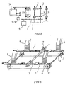
- the machine comprises two conveyor devices equipped with two latch chains 1 parallel, driven by means of toothed wheels 2 wedged on a shaft 3 driven in rotation using a gearmotor 4 via a transmission chain 5.
- Each conveyor device serves, in the successive order of intervention, an upstream cookie supply station 6, a filling depositing station 7 and a downstream cookie supply station 8.
- the stations are fitted with devices described in document FR-A No 2507583, published on 17.12.1982, filed by the holder company, allowing automatic regulation of the transfer of the cookies in a row and for this purpose comprising an upstream debtor device supplying the cookies with constant compaction and adjustable speed, and conveying them by a gutter with a descending trajectory in the direction of the cleat chains 1, which gutter is extended by a chute rounded downwards and rac roped to a well emerging above the conveyor device, the insufficient supply of the gutter or, conversely, an exaggerated packing of the cookies in the latter causing, respectively, a default or excess deviation from a height of setpoint, which difference is sensed by a detector in connection with the speed control circuit of the adjustable speed drive motor of the supply conveyor.
- the fodder depositing station consists of a fixed distribution cylinder 9 with a horizontal axis arranged perpendicularly to the movement of the transport devices and resting, at each of its ends, on two supports integral with the machine.
- This cylinder carries, at a spacing corresponding to that of the rows of cookies to be coated, distribution lights 10 aligned on a generator.
- the cylinder 9 is limited, at one of its ends, by a bearing 11 and, at the other end, by a supply box or tube 12 comprising a bearing 13, the connection of the latter with the cylinder being effected at using a flange assembly with tilting bolts 14 allowing rapid disassembly for cleaning the distribution assembly.
- This one-piece closure device consists of a cylindrical central part 15a which adjusts in the bore of the distribution cylinder, this central part being extended, on the supply box side 12 of the cylinder, by a hollow shaft 15b rotating in the bearing 13 thereof and, on the opposite side, by a shaft 15c journalling in the bearing 11 located at the end opposite to the feed box.
- the hollow shaft 15b extends an axial bore 1 5d of the central part 15a, which bore opens on the external cylinder thereof by a square hole 15e of shape and dimensions identical to those of the distribution lights 10.
- L free end of the hollow shaft 15b journalling in the bearing 13 of the feed box 12 is in connection with a feed inlet 16 disposed in the axis of said box, by means of a flexible connection sleeve 17.
- the bearing 13 is equipped with a seal 13a.
- An oblique tap 18 disposed on the feed box, on which a connection sleeve is also fixed, constitutes a second feed intake independent of the feed 16, this second feed delivering into the annular volume comprised between the bore of the cylinder. distribution 9 and the hollow shaft 15b of the closure device, this volume supplying the distribution lumen 10 closest to the supply box 12.
- the external rolling of the central part 15a of the closure device comprises, d on the one hand, a sealing ring 19 preventing any passage of fodder towards the distribution light 10 furthest from the distribution box, this light being supplied by the orifice 15e of said central part, and, on the other hand , a sealing ring 20 preventing any leakage of fodder towards the annular volume 21 located behind the central part, between the bore of the distribution cylinder 9 and the drive shaft 15f of the device. shutter yew.
- the central part 15a carries on its front face, on the supply box side, a cylindrical sector 15g whose height is determined so as to be able to close the distribution light 10 closest to said supply box.
- the simultaneous obturation of the two openings 10 is obtained by a limited angular rotation of the whole of the obturator device using a pneumatic cylinder 22 acting on an arm 23 mounted at the end of the shaft 15f, said cylinder being controlled by stopping and restarting the machine.
- the rotary distributor 24 mounted coaxially with the distribution cylinder 9 comprises, on a number of generators radially distributed at equal intervals, diffusion nozzles 25, of spacing equal to that of the distribution lights 10, the rotation of the distributor placing said nozzles in communication and lights. Sealing rings 26 prevent any leakage of fodder to the outside of the distribution device.
- the rotary distributor is coupled, at one of its ends, to a cylindrical sleeve 27 and, at the other end, to another cylindrical drive sleeve 28 carrying for this purpose a toothed pinion 20 meshing with the chain 5 ensuring the drive of the conveyor devices from the gear motor 4, this arrangement allowing synchronization of the speed of rotation of the dispenser with the speed of movement of the cookies.
- Attached to this synchronization device is a device, of known type, making it possible to adjust the phase of depositing the filling with respect to the cookie.
- the drive sleeves 27 and 28 rotate on wear rings 30 made of Ertalene interposed between the distribution cylinder and the rotary distributor.
- the feed of feed to the feeds 16 and 18 of the feed box 12 is carried out using positive displacement pumps or lobe pumps 31 and 32 whose speed of rotation is synchronized with the speed of drive in translation of the cleat chains 1 of the conveyor devices.
- the mechanical connection between said pumps and the gearmotor 4 for driving the chains comprises clutch devices 33 associated with a speed variator device 34. These clutches make it possible, when starting the machine, to operate only the pumps 31 and 32, the conveyor chains being stopped until a correct arrival of the stuffing at the diffusion nozzles 25 of the rotary distributor.
- the variator 34 makes it possible to adjust the flow rate of the filling in relation to that of the cookies.
- Fig. 3 represents the diagram of the regulation device making it possible to maintain a constant pressure upstream of the lobe pumps 31 and 32.
- This diagram groups together all the devices and piping circuits allowing the supply of the dispensing cylinder from the depositing station either with jam or with cream.
- This assembly consists of a storage 33 containing the fodder, which is taken up at the bottom by an extraction pump 34 in connection with a pressure regulator 35, of the membrane type, acting as an accumulator, itself in connection with either a mixer 36, in the case of jam, or a reserve capacity 37, in the case of cream.
- Flavor 38 and acid 39 arrive on mixer 36, these additives being introduced by the delivery of a dosing pump 40 through non-return valves 41 and 42, which dosing pump is controlled by the pump. with lobes 32.
- Three-way valves 43 and 44 allow the supply of the distribution cylinder by one or the other of the cream or jam circuits.
- the displacements of the diaphragm of the pressure accumulator regulator 35 control the speed variations or the stopping of the extraction pump 34, as well as the stopping of the pump 31 or 32.
- the diaphragm is integral with a sliding rod 45 carrying an index, which acts, during its translational movement, on electrical control contacts.
- an increase in pressure in the volume located under the membrane causes it to deform upward, forcing the rod 45 to go up, the index finger acting on a contact controlling a slowing down of the speed of rotation. of the extraction pump 34; the slower contact is maintained by a magnet system as long as the rod goes up.
- the index then intervenes on another contact controlling the stopping of said extraction pump; these contacts are broken as soon as the rod descends.
- a drop in pressure in the volume located under the membrane deforms the latter downwards.
- the index of the rod 45 in this case controls an acceleration of the speed of rotation of the extraction pump by a contact maintained during the descent of the rod; when this pressure drop increases, the index intervenes on a contact stopping the lobe pumps 31 and 32.
- the machine object of the invention can be used for the manufacture of all coated products, such as cookies coated with cream, chocolate or jam.
Landscapes
- Life Sciences & Earth Sciences (AREA)
- Engineering & Computer Science (AREA)
- Food Science & Technology (AREA)
- Confectionery (AREA)
- Coating Apparatus (AREA)
- Fodder In General (AREA)
- Manufacturing And Processing Devices For Dough (AREA)
Applications Claiming Priority (2)
| Application Number | Priority Date | Filing Date | Title |
|---|---|---|---|
| FR8123788 | 1981-12-16 | ||
| FR8123788A FR2517992A1 (fr) | 1981-12-16 | 1981-12-16 | Nouvelle machine permettant la fabrication de produits enduits tels que biscuits ou autres |
Publications (2)
| Publication Number | Publication Date |
|---|---|
| EP0082085A1 EP0082085A1 (fr) | 1983-06-22 |
| EP0082085B1 true EP0082085B1 (fr) | 1985-04-10 |
Family
ID=9265211
Family Applications (1)
| Application Number | Title | Priority Date | Filing Date |
|---|---|---|---|
| EP82402298A Expired EP0082085B1 (fr) | 1981-12-16 | 1982-12-14 | Machine permettant la fabrication de produits enduits tels que biscuits ou autres |
Country Status (7)
| Country | Link |
|---|---|
| US (1) | US4502376A (Direct) |
| EP (1) | EP0082085B1 (Direct) |
| CA (1) | CA1197089A (Direct) |
| DE (1) | DE3263038D1 (Direct) |
| ES (1) | ES8308723A1 (Direct) |
| FR (1) | FR2517992A1 (Direct) |
| GB (1) | GB2111365B (Direct) |
Families Citing this family (12)
| Publication number | Priority date | Publication date | Assignee | Title |
|---|---|---|---|---|
| US4469021A (en) * | 1982-12-17 | 1984-09-04 | Peters Machinery Company | Dual feed stencil assembly for a sandwiching machine |
| EP0189299A3 (en) * | 1985-01-22 | 1987-09-02 | Apv Corporation Limited | Improvements in or relating to creaming apparatus |
| US4850833A (en) * | 1985-03-11 | 1989-07-25 | Nabisco Brands, Inc. | Pistonless icing depositor |
| DE69523894T2 (de) * | 1995-05-09 | 2002-04-11 | Societe Des Produits Nestle S.A., Vevey | Vorrichtung und Verfahren zur Dosierung einen Nahrungsmittels in Form einer Musters |
| US6194014B1 (en) | 1996-12-20 | 2001-02-27 | Nestec S.A. | Process for preparing chocolate coating and confectionary products containing same |
| AT409704B (de) * | 1999-08-03 | 2002-10-25 | Koenig Maschinen Gmbh | Walze für die aufbringung zumindest eines strömungsfähigen mediums auf teig |
| EP1815972B1 (en) * | 2006-02-06 | 2013-12-18 | ABB Research Ltd. | Press line system and method |
| US8578842B2 (en) | 2009-10-12 | 2013-11-12 | Hans van der Ent | Apparatuses and methods for the production of sandwich food items |
| US8334005B2 (en) * | 2008-11-14 | 2012-12-18 | Kraft Foods Global Brands Llc | Ribbon cutter apparatus and method for making sandwich baked goods |
| US8683917B2 (en) * | 2010-01-04 | 2014-04-01 | Illinois Tool Works Inc. | Stencil assembly for depositing food product and related sandwiching machine |
| NL2026053B1 (nl) * | 2020-07-13 | 2022-03-15 | B V Machf Houdijk | Depositie-inrichting voor een viskeuze vloeistof voor de productie van koekjes. |
| CN113951302A (zh) * | 2021-10-25 | 2022-01-21 | 谢娟 | 一种食品加工用夹心饼干奶油涂抹设备 |
Family Cites Families (3)
| Publication number | Priority date | Publication date | Assignee | Title |
|---|---|---|---|---|
| US2993453A (en) * | 1958-12-15 | 1961-07-25 | Peters Mach Co | Sandwiching machine |
| US3340824A (en) * | 1965-08-23 | 1967-09-12 | Peters Mach Co | Sandwiching machines |
| US4162882A (en) * | 1978-03-22 | 1979-07-31 | Peters Machinery Company | Valve mechanism for sandwich creme |
-
1981
- 1981-12-16 FR FR8123788A patent/FR2517992A1/fr active Granted
-
1982
- 1982-08-20 GB GB08224026A patent/GB2111365B/en not_active Expired
- 1982-08-30 US US06/412,922 patent/US4502376A/en not_active Expired - Lifetime
- 1982-12-14 DE DE8282402298T patent/DE3263038D1/de not_active Expired
- 1982-12-14 EP EP82402298A patent/EP0082085B1/fr not_active Expired
- 1982-12-15 CA CA000417740A patent/CA1197089A/en not_active Expired
- 1982-12-15 ES ES518231A patent/ES8308723A1/es not_active Expired
Also Published As
| Publication number | Publication date |
|---|---|
| FR2517992A1 (fr) | 1983-06-17 |
| EP0082085A1 (fr) | 1983-06-22 |
| US4502376A (en) | 1985-03-05 |
| ES518231A0 (es) | 1983-10-01 |
| FR2517992B1 (Direct) | 1984-07-13 |
| CA1197089A (en) | 1985-11-26 |
| GB2111365A (en) | 1983-07-06 |
| ES8308723A1 (es) | 1983-10-01 |
| GB2111365B (en) | 1985-02-27 |
| DE3263038D1 (en) | 1985-05-15 |
Similar Documents
| Publication | Publication Date | Title |
|---|---|---|
| EP0082085B1 (fr) | Machine permettant la fabrication de produits enduits tels que biscuits ou autres | |
| US4077180A (en) | Method and apparatus for packaging fluent material | |
| CH416142A (fr) | Appareil pour la constitution de doses pondérales égales de tabac, ou matière similaire | |
| EP3648609B1 (fr) | Dispositif pour etaler une pate alimentaire coulante sur une plaque de cuisson | |
| FR2540089A1 (fr) | Machine de remplissage volumetrique | |
| WO2003068602A1 (fr) | Installation de remplissage de récipients selon des compositions de produit variables | |
| GB2297955A (en) | Product conveyor line | |
| EP0469972B1 (fr) | Dispositif d'étalement d'une pâte coulante, telle qu'une pâte alimentaire crue, sur une face horizontale, telle qu'une face de cuisson | |
| EP0269507B1 (fr) | Procédé et installation de remplissage de récipients avec un mélange d'au moins deux produits pâteux et/ou liquides | |
| KR20140137459A (ko) | 점성 매스를 계량 및 이송하기 위한 장치 | |
| FR2512776A1 (fr) | Machine de remplissage de conteneurs | |
| EP3367802A1 (fr) | Système et procédé pour former des steaks hachés | |
| US4708054A (en) | Creaming apparatus | |
| JP2004519258A (ja) | 食品に飾り付けをするための液体成分またはクリーム状成分用調量調量分配装置 | |
| US2917272A (en) | Apparatus for dispensing heavy consistency fluid | |
| CH674917A5 (Direct) | ||
| US4491159A (en) | High speed liquid dispenser | |
| US1424534A (en) | Wrapping machine | |
| FR2515607A2 (fr) | Machine de remplissage de conteneurs | |
| US3499586A (en) | Confectionery dispenser | |
| US1121433A (en) | Depositing-machine. | |
| FR2513936A1 (fr) | Procede et appareil pour former des boules creuses | |
| FR2483180A3 (fr) | Machine pour le faconnage de bandes de pate alimentaire | |
| IE53990B1 (en) | Machine for preparing coated products | |
| FR2866705A1 (fr) | Dispositif de dosage d'un liquide a l'interieur d'un contenant et procede associe |
Legal Events
| Date | Code | Title | Description |
|---|---|---|---|
| PUAI | Public reference made under article 153(3) epc to a published international application that has entered the european phase |
Free format text: ORIGINAL CODE: 0009012 |
|
| AK | Designated contracting states |
Designated state(s): BE CH DE IT LI NL |
|
| 17P | Request for examination filed |
Effective date: 19830815 |
|
| ITF | It: translation for a ep patent filed | ||
| GRAA | (expected) grant |
Free format text: ORIGINAL CODE: 0009210 |
|
| AK | Designated contracting states |
Designated state(s): BE CH DE IT LI NL |
|
| REF | Corresponds to: |
Ref document number: 3263038 Country of ref document: DE Date of ref document: 19850515 |
|
| PLBE | No opposition filed within time limit |
Free format text: ORIGINAL CODE: 0009261 |
|
| STAA | Information on the status of an ep patent application or granted ep patent |
Free format text: STATUS: NO OPPOSITION FILED WITHIN TIME LIMIT |
|
| 26N | No opposition filed | ||
| PGFP | Annual fee paid to national office [announced via postgrant information from national office to epo] |
Ref country code: CH Payment date: 19911220 Year of fee payment: 10 |
|
| ITTA | It: last paid annual fee | ||
| PG25 | Lapsed in a contracting state [announced via postgrant information from national office to epo] |
Ref country code: LI Effective date: 19921231 Ref country code: CH Effective date: 19921231 |
|
| REG | Reference to a national code |
Ref country code: CH Ref legal event code: PL |
|
| PGFP | Annual fee paid to national office [announced via postgrant information from national office to epo] |
Ref country code: BE Payment date: 20011213 Year of fee payment: 20 |
|
| PGFP | Annual fee paid to national office [announced via postgrant information from national office to epo] |
Ref country code: NL Payment date: 20011221 Year of fee payment: 20 |
|
| PGFP | Annual fee paid to national office [announced via postgrant information from national office to epo] |
Ref country code: DE Payment date: 20020226 Year of fee payment: 20 |
|
| PG25 | Lapsed in a contracting state [announced via postgrant information from national office to epo] |
Ref country code: NL Free format text: LAPSE BECAUSE OF EXPIRATION OF PROTECTION Effective date: 20021214 |
|
| BE20 | Be: patent expired |
Owner name: *BISCUITERIE NANTAISE - BN Effective date: 20021214 |
|
| NLV7 | Nl: ceased due to reaching the maximum lifetime of a patent |
Effective date: 20021214 |