EP0081472A2 - Procédé et dispositif pour récupérer de l'argon d'une installation de séparation de l'air destinée pour l'unique production de l'oxygène - Google Patents
Procédé et dispositif pour récupérer de l'argon d'une installation de séparation de l'air destinée pour l'unique production de l'oxygène Download PDFInfo
- Publication number
- EP0081472A2 EP0081472A2 EP82850252A EP82850252A EP0081472A2 EP 0081472 A2 EP0081472 A2 EP 0081472A2 EP 82850252 A EP82850252 A EP 82850252A EP 82850252 A EP82850252 A EP 82850252A EP 0081472 A2 EP0081472 A2 EP 0081472A2
- Authority
- EP
- European Patent Office
- Prior art keywords
- argon
- column
- oxygen
- stream
- liquid
- Prior art date
- Legal status (The legal status is an assumption and is not a legal conclusion. Google has not performed a legal analysis and makes no representation as to the accuracy of the status listed.)
- Granted
Links
Images


Classifications
-
- F—MECHANICAL ENGINEERING; LIGHTING; HEATING; WEAPONS; BLASTING
- F25—REFRIGERATION OR COOLING; COMBINED HEATING AND REFRIGERATION SYSTEMS; HEAT PUMP SYSTEMS; MANUFACTURE OR STORAGE OF ICE; LIQUEFACTION SOLIDIFICATION OF GASES
- F25J—LIQUEFACTION, SOLIDIFICATION OR SEPARATION OF GASES OR GASEOUS OR LIQUEFIED GASEOUS MIXTURES BY PRESSURE AND COLD TREATMENT OR BY BRINGING THEM INTO THE SUPERCRITICAL STATE
- F25J3/00—Processes or apparatus for separating the constituents of gaseous or liquefied gaseous mixtures involving the use of liquefaction or solidification
- F25J3/02—Processes or apparatus for separating the constituents of gaseous or liquefied gaseous mixtures involving the use of liquefaction or solidification by rectification, i.e. by continuous interchange of heat and material between a vapour stream and a liquid stream
- F25J3/04—Processes or apparatus for separating the constituents of gaseous or liquefied gaseous mixtures involving the use of liquefaction or solidification by rectification, i.e. by continuous interchange of heat and material between a vapour stream and a liquid stream for air
- F25J3/04248—Generation of cold for compensating heat leaks or liquid production, e.g. by Joule-Thompson expansion
- F25J3/04254—Generation of cold for compensating heat leaks or liquid production, e.g. by Joule-Thompson expansion using the cold stored in external cryogenic fluids
- F25J3/0426—The cryogenic component does not participate in the fractionation
-
- F—MECHANICAL ENGINEERING; LIGHTING; HEATING; WEAPONS; BLASTING
- F25—REFRIGERATION OR COOLING; COMBINED HEATING AND REFRIGERATION SYSTEMS; HEAT PUMP SYSTEMS; MANUFACTURE OR STORAGE OF ICE; LIQUEFACTION SOLIDIFICATION OF GASES
- F25J—LIQUEFACTION, SOLIDIFICATION OR SEPARATION OF GASES OR GASEOUS OR LIQUEFIED GASEOUS MIXTURES BY PRESSURE AND COLD TREATMENT OR BY BRINGING THEM INTO THE SUPERCRITICAL STATE
- F25J3/00—Processes or apparatus for separating the constituents of gaseous or liquefied gaseous mixtures involving the use of liquefaction or solidification
- F25J3/02—Processes or apparatus for separating the constituents of gaseous or liquefied gaseous mixtures involving the use of liquefaction or solidification by rectification, i.e. by continuous interchange of heat and material between a vapour stream and a liquid stream
- F25J3/04—Processes or apparatus for separating the constituents of gaseous or liquefied gaseous mixtures involving the use of liquefaction or solidification by rectification, i.e. by continuous interchange of heat and material between a vapour stream and a liquid stream for air
- F25J3/04248—Generation of cold for compensating heat leaks or liquid production, e.g. by Joule-Thompson expansion
- F25J3/04278—Generation of cold for compensating heat leaks or liquid production, e.g. by Joule-Thompson expansion using external refrigeration units, e.g. closed mechanical or regenerative refrigeration units
-
- F—MECHANICAL ENGINEERING; LIGHTING; HEATING; WEAPONS; BLASTING
- F25—REFRIGERATION OR COOLING; COMBINED HEATING AND REFRIGERATION SYSTEMS; HEAT PUMP SYSTEMS; MANUFACTURE OR STORAGE OF ICE; LIQUEFACTION SOLIDIFICATION OF GASES
- F25J—LIQUEFACTION, SOLIDIFICATION OR SEPARATION OF GASES OR GASEOUS OR LIQUEFIED GASEOUS MIXTURES BY PRESSURE AND COLD TREATMENT OR BY BRINGING THEM INTO THE SUPERCRITICAL STATE
- F25J3/00—Processes or apparatus for separating the constituents of gaseous or liquefied gaseous mixtures involving the use of liquefaction or solidification
- F25J3/02—Processes or apparatus for separating the constituents of gaseous or liquefied gaseous mixtures involving the use of liquefaction or solidification by rectification, i.e. by continuous interchange of heat and material between a vapour stream and a liquid stream
- F25J3/04—Processes or apparatus for separating the constituents of gaseous or liquefied gaseous mixtures involving the use of liquefaction or solidification by rectification, i.e. by continuous interchange of heat and material between a vapour stream and a liquid stream for air
- F25J3/04406—Processes or apparatus for separating the constituents of gaseous or liquefied gaseous mixtures involving the use of liquefaction or solidification by rectification, i.e. by continuous interchange of heat and material between a vapour stream and a liquid stream for air using a dual pressure main column system
- F25J3/04412—Processes or apparatus for separating the constituents of gaseous or liquefied gaseous mixtures involving the use of liquefaction or solidification by rectification, i.e. by continuous interchange of heat and material between a vapour stream and a liquid stream for air using a dual pressure main column system in a classical double column flowsheet, i.e. with thermal coupling by a main reboiler-condenser in the bottom of low pressure respectively top of high pressure column
-
- F—MECHANICAL ENGINEERING; LIGHTING; HEATING; WEAPONS; BLASTING
- F25—REFRIGERATION OR COOLING; COMBINED HEATING AND REFRIGERATION SYSTEMS; HEAT PUMP SYSTEMS; MANUFACTURE OR STORAGE OF ICE; LIQUEFACTION SOLIDIFICATION OF GASES
- F25J—LIQUEFACTION, SOLIDIFICATION OR SEPARATION OF GASES OR GASEOUS OR LIQUEFIED GASEOUS MIXTURES BY PRESSURE AND COLD TREATMENT OR BY BRINGING THEM INTO THE SUPERCRITICAL STATE
- F25J3/00—Processes or apparatus for separating the constituents of gaseous or liquefied gaseous mixtures involving the use of liquefaction or solidification
- F25J3/02—Processes or apparatus for separating the constituents of gaseous or liquefied gaseous mixtures involving the use of liquefaction or solidification by rectification, i.e. by continuous interchange of heat and material between a vapour stream and a liquid stream
- F25J3/04—Processes or apparatus for separating the constituents of gaseous or liquefied gaseous mixtures involving the use of liquefaction or solidification by rectification, i.e. by continuous interchange of heat and material between a vapour stream and a liquid stream for air
- F25J3/04642—Recovering noble gases from air
- F25J3/04648—Recovering noble gases from air argon
- F25J3/04654—Producing crude argon in a crude argon column
- F25J3/04666—Producing crude argon in a crude argon column as a parallel working rectification column of the low pressure column in a dual pressure main column system
- F25J3/04672—Producing crude argon in a crude argon column as a parallel working rectification column of the low pressure column in a dual pressure main column system having a top condenser
- F25J3/04678—Producing crude argon in a crude argon column as a parallel working rectification column of the low pressure column in a dual pressure main column system having a top condenser cooled by oxygen enriched liquid from high pressure column bottoms
-
- F—MECHANICAL ENGINEERING; LIGHTING; HEATING; WEAPONS; BLASTING
- F25—REFRIGERATION OR COOLING; COMBINED HEATING AND REFRIGERATION SYSTEMS; HEAT PUMP SYSTEMS; MANUFACTURE OR STORAGE OF ICE; LIQUEFACTION SOLIDIFICATION OF GASES
- F25J—LIQUEFACTION, SOLIDIFICATION OR SEPARATION OF GASES OR GASEOUS OR LIQUEFIED GASEOUS MIXTURES BY PRESSURE AND COLD TREATMENT OR BY BRINGING THEM INTO THE SUPERCRITICAL STATE
- F25J3/00—Processes or apparatus for separating the constituents of gaseous or liquefied gaseous mixtures involving the use of liquefaction or solidification
- F25J3/02—Processes or apparatus for separating the constituents of gaseous or liquefied gaseous mixtures involving the use of liquefaction or solidification by rectification, i.e. by continuous interchange of heat and material between a vapour stream and a liquid stream
- F25J3/04—Processes or apparatus for separating the constituents of gaseous or liquefied gaseous mixtures involving the use of liquefaction or solidification by rectification, i.e. by continuous interchange of heat and material between a vapour stream and a liquid stream for air
- F25J3/04642—Recovering noble gases from air
- F25J3/04648—Recovering noble gases from air argon
- F25J3/04654—Producing crude argon in a crude argon column
- F25J3/04709—Producing crude argon in a crude argon column as an auxiliary column system in at least a dual pressure main column system
- F25J3/04715—The auxiliary column system simultaneously produces oxygen
-
- F—MECHANICAL ENGINEERING; LIGHTING; HEATING; WEAPONS; BLASTING
- F25—REFRIGERATION OR COOLING; COMBINED HEATING AND REFRIGERATION SYSTEMS; HEAT PUMP SYSTEMS; MANUFACTURE OR STORAGE OF ICE; LIQUEFACTION SOLIDIFICATION OF GASES
- F25J—LIQUEFACTION, SOLIDIFICATION OR SEPARATION OF GASES OR GASEOUS OR LIQUEFIED GASEOUS MIXTURES BY PRESSURE AND COLD TREATMENT OR BY BRINGING THEM INTO THE SUPERCRITICAL STATE
- F25J3/00—Processes or apparatus for separating the constituents of gaseous or liquefied gaseous mixtures involving the use of liquefaction or solidification
- F25J3/02—Processes or apparatus for separating the constituents of gaseous or liquefied gaseous mixtures involving the use of liquefaction or solidification by rectification, i.e. by continuous interchange of heat and material between a vapour stream and a liquid stream
- F25J3/04—Processes or apparatus for separating the constituents of gaseous or liquefied gaseous mixtures involving the use of liquefaction or solidification by rectification, i.e. by continuous interchange of heat and material between a vapour stream and a liquid stream for air
- F25J3/04642—Recovering noble gases from air
- F25J3/04648—Recovering noble gases from air argon
- F25J3/04721—Producing pure argon, e.g. recovered from a crude argon column
- F25J3/04733—Producing pure argon, e.g. recovered from a crude argon column using a hybrid system, e.g. using adsorption, permeation or catalytic reaction
-
- F—MECHANICAL ENGINEERING; LIGHTING; HEATING; WEAPONS; BLASTING
- F25—REFRIGERATION OR COOLING; COMBINED HEATING AND REFRIGERATION SYSTEMS; HEAT PUMP SYSTEMS; MANUFACTURE OR STORAGE OF ICE; LIQUEFACTION SOLIDIFICATION OF GASES
- F25J—LIQUEFACTION, SOLIDIFICATION OR SEPARATION OF GASES OR GASEOUS OR LIQUEFIED GASEOUS MIXTURES BY PRESSURE AND COLD TREATMENT OR BY BRINGING THEM INTO THE SUPERCRITICAL STATE
- F25J3/00—Processes or apparatus for separating the constituents of gaseous or liquefied gaseous mixtures involving the use of liquefaction or solidification
- F25J3/02—Processes or apparatus for separating the constituents of gaseous or liquefied gaseous mixtures involving the use of liquefaction or solidification by rectification, i.e. by continuous interchange of heat and material between a vapour stream and a liquid stream
- F25J3/04—Processes or apparatus for separating the constituents of gaseous or liquefied gaseous mixtures involving the use of liquefaction or solidification by rectification, i.e. by continuous interchange of heat and material between a vapour stream and a liquid stream for air
- F25J3/04763—Start-up or control of the process; Details of the apparatus used
- F25J3/04866—Construction and layout of air fractionation equipments, e.g. valves, machines
- F25J3/04951—Arrangements of multiple air fractionation units or multiple equipments fulfilling the same process step, e.g. multiple trains in a network
- F25J3/04963—Arrangements of multiple air fractionation units or multiple equipments fulfilling the same process step, e.g. multiple trains in a network and inter-connecting equipment within or downstream of the fractionation unit(s)
-
- F—MECHANICAL ENGINEERING; LIGHTING; HEATING; WEAPONS; BLASTING
- F25—REFRIGERATION OR COOLING; COMBINED HEATING AND REFRIGERATION SYSTEMS; HEAT PUMP SYSTEMS; MANUFACTURE OR STORAGE OF ICE; LIQUEFACTION SOLIDIFICATION OF GASES
- F25J—LIQUEFACTION, SOLIDIFICATION OR SEPARATION OF GASES OR GASEOUS OR LIQUEFIED GASEOUS MIXTURES BY PRESSURE AND COLD TREATMENT OR BY BRINGING THEM INTO THE SUPERCRITICAL STATE
- F25J3/00—Processes or apparatus for separating the constituents of gaseous or liquefied gaseous mixtures involving the use of liquefaction or solidification
- F25J3/02—Processes or apparatus for separating the constituents of gaseous or liquefied gaseous mixtures involving the use of liquefaction or solidification by rectification, i.e. by continuous interchange of heat and material between a vapour stream and a liquid stream
- F25J3/04—Processes or apparatus for separating the constituents of gaseous or liquefied gaseous mixtures involving the use of liquefaction or solidification by rectification, i.e. by continuous interchange of heat and material between a vapour stream and a liquid stream for air
- F25J3/04763—Start-up or control of the process; Details of the apparatus used
- F25J3/04866—Construction and layout of air fractionation equipments, e.g. valves, machines
- F25J3/04969—Retrofitting or revamping of an existing air fractionation unit
-
- F—MECHANICAL ENGINEERING; LIGHTING; HEATING; WEAPONS; BLASTING
- F25—REFRIGERATION OR COOLING; COMBINED HEATING AND REFRIGERATION SYSTEMS; HEAT PUMP SYSTEMS; MANUFACTURE OR STORAGE OF ICE; LIQUEFACTION SOLIDIFICATION OF GASES
- F25J—LIQUEFACTION, SOLIDIFICATION OR SEPARATION OF GASES OR GASEOUS OR LIQUEFIED GASEOUS MIXTURES BY PRESSURE AND COLD TREATMENT OR BY BRINGING THEM INTO THE SUPERCRITICAL STATE
- F25J2200/00—Processes or apparatus using separation by rectification
- F25J2200/04—Processes or apparatus using separation by rectification in a dual pressure main column system
- F25J2200/06—Processes or apparatus using separation by rectification in a dual pressure main column system in a classical double column flow-sheet, i.e. with thermal coupling by a main reboiler-condenser in the bottom of low pressure respectively top of high pressure column
-
- F—MECHANICAL ENGINEERING; LIGHTING; HEATING; WEAPONS; BLASTING
- F25—REFRIGERATION OR COOLING; COMBINED HEATING AND REFRIGERATION SYSTEMS; HEAT PUMP SYSTEMS; MANUFACTURE OR STORAGE OF ICE; LIQUEFACTION SOLIDIFICATION OF GASES
- F25J—LIQUEFACTION, SOLIDIFICATION OR SEPARATION OF GASES OR GASEOUS OR LIQUEFIED GASEOUS MIXTURES BY PRESSURE AND COLD TREATMENT OR BY BRINGING THEM INTO THE SUPERCRITICAL STATE
- F25J2200/00—Processes or apparatus using separation by rectification
- F25J2200/08—Processes or apparatus using separation by rectification in a triple pressure main column system
-
- F—MECHANICAL ENGINEERING; LIGHTING; HEATING; WEAPONS; BLASTING
- F25—REFRIGERATION OR COOLING; COMBINED HEATING AND REFRIGERATION SYSTEMS; HEAT PUMP SYSTEMS; MANUFACTURE OR STORAGE OF ICE; LIQUEFACTION SOLIDIFICATION OF GASES
- F25J—LIQUEFACTION, SOLIDIFICATION OR SEPARATION OF GASES OR GASEOUS OR LIQUEFIED GASEOUS MIXTURES BY PRESSURE AND COLD TREATMENT OR BY BRINGING THEM INTO THE SUPERCRITICAL STATE
- F25J2205/00—Processes or apparatus using other separation and/or other processing means
- F25J2205/02—Processes or apparatus using other separation and/or other processing means using simple phase separation in a vessel or drum
-
- F—MECHANICAL ENGINEERING; LIGHTING; HEATING; WEAPONS; BLASTING
- F25—REFRIGERATION OR COOLING; COMBINED HEATING AND REFRIGERATION SYSTEMS; HEAT PUMP SYSTEMS; MANUFACTURE OR STORAGE OF ICE; LIQUEFACTION SOLIDIFICATION OF GASES
- F25J—LIQUEFACTION, SOLIDIFICATION OR SEPARATION OF GASES OR GASEOUS OR LIQUEFIED GASEOUS MIXTURES BY PRESSURE AND COLD TREATMENT OR BY BRINGING THEM INTO THE SUPERCRITICAL STATE
- F25J2205/00—Processes or apparatus using other separation and/or other processing means
- F25J2205/82—Processes or apparatus using other separation and/or other processing means using a reactor with combustion or catalytic reaction
-
- F—MECHANICAL ENGINEERING; LIGHTING; HEATING; WEAPONS; BLASTING
- F25—REFRIGERATION OR COOLING; COMBINED HEATING AND REFRIGERATION SYSTEMS; HEAT PUMP SYSTEMS; MANUFACTURE OR STORAGE OF ICE; LIQUEFACTION SOLIDIFICATION OF GASES
- F25J—LIQUEFACTION, SOLIDIFICATION OR SEPARATION OF GASES OR GASEOUS OR LIQUEFIED GASEOUS MIXTURES BY PRESSURE AND COLD TREATMENT OR BY BRINGING THEM INTO THE SUPERCRITICAL STATE
- F25J2210/00—Processes characterised by the type or other details of the feed stream
- F25J2210/42—Nitrogen
-
- F—MECHANICAL ENGINEERING; LIGHTING; HEATING; WEAPONS; BLASTING
- F25—REFRIGERATION OR COOLING; COMBINED HEATING AND REFRIGERATION SYSTEMS; HEAT PUMP SYSTEMS; MANUFACTURE OR STORAGE OF ICE; LIQUEFACTION SOLIDIFICATION OF GASES
- F25J—LIQUEFACTION, SOLIDIFICATION OR SEPARATION OF GASES OR GASEOUS OR LIQUEFIED GASEOUS MIXTURES BY PRESSURE AND COLD TREATMENT OR BY BRINGING THEM INTO THE SUPERCRITICAL STATE
- F25J2270/00—Refrigeration techniques used
- F25J2270/12—External refrigeration with liquid vaporising loop
-
- F—MECHANICAL ENGINEERING; LIGHTING; HEATING; WEAPONS; BLASTING
- F25—REFRIGERATION OR COOLING; COMBINED HEATING AND REFRIGERATION SYSTEMS; HEAT PUMP SYSTEMS; MANUFACTURE OR STORAGE OF ICE; LIQUEFACTION SOLIDIFICATION OF GASES
- F25J—LIQUEFACTION, SOLIDIFICATION OR SEPARATION OF GASES OR GASEOUS OR LIQUEFIED GASEOUS MIXTURES BY PRESSURE AND COLD TREATMENT OR BY BRINGING THEM INTO THE SUPERCRITICAL STATE
- F25J2270/00—Refrigeration techniques used
- F25J2270/14—External refrigeration with work-producing gas expansion loop
-
- F—MECHANICAL ENGINEERING; LIGHTING; HEATING; WEAPONS; BLASTING
- F25—REFRIGERATION OR COOLING; COMBINED HEATING AND REFRIGERATION SYSTEMS; HEAT PUMP SYSTEMS; MANUFACTURE OR STORAGE OF ICE; LIQUEFACTION SOLIDIFICATION OF GASES
- F25J—LIQUEFACTION, SOLIDIFICATION OR SEPARATION OF GASES OR GASEOUS OR LIQUEFIED GASEOUS MIXTURES BY PRESSURE AND COLD TREATMENT OR BY BRINGING THEM INTO THE SUPERCRITICAL STATE
- F25J2270/00—Refrigeration techniques used
- F25J2270/42—Quasi-closed internal or closed external nitrogen refrigeration cycle
-
- F—MECHANICAL ENGINEERING; LIGHTING; HEATING; WEAPONS; BLASTING
- F25—REFRIGERATION OR COOLING; COMBINED HEATING AND REFRIGERATION SYSTEMS; HEAT PUMP SYSTEMS; MANUFACTURE OR STORAGE OF ICE; LIQUEFACTION SOLIDIFICATION OF GASES
- F25J—LIQUEFACTION, SOLIDIFICATION OR SEPARATION OF GASES OR GASEOUS OR LIQUEFIED GASEOUS MIXTURES BY PRESSURE AND COLD TREATMENT OR BY BRINGING THEM INTO THE SUPERCRITICAL STATE
- F25J2270/00—Refrigeration techniques used
- F25J2270/60—Closed external refrigeration cycle with single component refrigerant [SCR], e.g. C1-, C2- or C3-hydrocarbons
-
- Y—GENERAL TAGGING OF NEW TECHNOLOGICAL DEVELOPMENTS; GENERAL TAGGING OF CROSS-SECTIONAL TECHNOLOGIES SPANNING OVER SEVERAL SECTIONS OF THE IPC; TECHNICAL SUBJECTS COVERED BY FORMER USPC CROSS-REFERENCE ART COLLECTIONS [XRACs] AND DIGESTS
- Y10—TECHNICAL SUBJECTS COVERED BY FORMER USPC
- Y10S—TECHNICAL SUBJECTS COVERED BY FORMER USPC CROSS-REFERENCE ART COLLECTIONS [XRACs] AND DIGESTS
- Y10S62/00—Refrigeration
- Y10S62/923—Inert gas
- Y10S62/924—Argon
Definitions
- This invention relates generally to the field of cryogenic air separation and more particularly to the production of argon from the cryogenic separation of air.
- Argon is a highly useful inert gas which in the past has been used for many applications such as in lightbulbs, for welding of metals, and for various other metallurgical uses. Approximately one percent of atmospheric air is argon. Argon is produced commercially in cryogenic air separation plants which also produce oxygen and nitrogen. Recently the demand for argon has increased dramatically due primarily to the use of argon in the refining of stainless and other steels.
- the additional argon recovery system should be such that production outage of the existing plant is minimized during installation of the argon recovery equipment.
- the retrofit recovery system should be such that it produces crude argon product compatible with existing argon refining equipment.
- the retrofit system should not substantially detract from operation of the existing air plant. It is also desirable that the additional argon producing system recover a high percentage of the available argon.
- this invention comprises:
- an apparatus for producing oxygen by the separation of air comprising a high pressure column in heat exchange relation with a low pressure column, the improvement comprising:
- column is used to mean a distillation or fractionation column, ie., a contacting column or zone wherein liquid and vapor phases are countercurrently contacted to effect separation of a fluid mixture, as, for example, by contacting of the vapor and liquid phases on a series of vertically spaced trays or plates mounted within the column, or alternatively on packing elements with which the column is filled.
- a distillation or fractionation column ie., a contacting column or zone wherein liquid and vapor phases are countercurrently contacted to effect separation of a fluid mixture, as, for example, by contacting of the vapor and liquid phases on a series of vertically spaced trays or plates mounted within the column, or alternatively on packing elements with which the column is filled.
- double column is used to mean a higher pressure column having its upper end in heat exchange relation with the lower end of a low pressure column. Examples of a double column appear in Oxfordauer "The Separation of Gases", University Press, 1949.
- heat pump circuit is used to mean a recirculating fluid arrangement whereby heat is removed at a lower temperature and added at a higher temperature.
- heat pump arrangement involves vaporization of the recirculating fluid (or working medium) to remove heat, and condensation of the fluid to add heat.
- This invention provides a process and apparatus for producing argon by modification of existing cryogenic air separation processes and apparatus which produce oxygen, and which permits economic recovery of argon.
- the process and apparatus of this invention produce argon at a purity of at least 96 mole percent thus allowing its relatively easy employment in existing argon refineries.
- the process and apparatus of this invention also produce oxygen at a purity of at least 99 mole percent thus allowing its direct intermixture with the product from the existing oxygen-only plant.
- the improved process of this invention employs an auxiliary two-section crude argon column driven by an independent heat pump cycle.
- the column feed is taken from an intermediate point within the existing air separation plant low pressure column and is essentially an argon-oxygen mixture with minimal nitrogen content.
- This feed stream is separated within the argon column into two product streams.
- One product stream, taken from the bottom of the argon column is a product oxygen stream at a composition similar to that of the product oxygen stream taken from the main air separation plant low pressure column.
- the other product steam is a crude argon product at a composition compatible with existing argon refining systems.
- the argon column system can include a refrigeration source which can, for example, be either added liquid nitrogen in the top condenser of the argon column or other appropriate point in the heat pump circuit or it can be liquid oxygen in the bottom condenser of the column, or, refrigeration may be provided by a turbine expansion of part of the circulating fluid in the heat pump circuit.
- the refrigeration source and means by which it is supplied to the argon column system is an engineering judgment well within the competence of one skilled in this art and will depend, inter alia, on equipment availability and the liquid supply availability.
- the feed in-the argon column is taken from the main air separation plant low pressure column at a point above the bottom or product oxygen location.
- the feed quantity transferred to the argon column will range from 3 to 9 volume percent of the feed to the main air separation plant or oxygen production facility, preferably from 5 to 7 percent.
- the feed stream is taken from the low pressure column at a point such that its composition is from 10 to 18 percent, preferably from 12 to 16 percent argon.
- the nitrogen content of the feed stream should not exceed 0.5 percent and preferably does not exceed 0.2 percent.
- the balance of the feed stream is composed primarily of oxygen.
- the heat pump flow circuit circulates 3 to 7 times the feedstream flow rate, preferably from 4 to 5 times the flow rate.
- Any suitable fluid may be used as the heat pump fluid including nitrogen, oxygen, argon, crude argon mixture or clean and dry air.
- the preferred heat pump fluid is nitrogen.
- Figure 1 illustrates a preferred embodiment of the process and apparatus of this invention. Only the columns section of the existing oxygen-only air separation plant is illustrated since all other sections such as the heat exchangers and associated warm end equipment do not influence the process and apparatus combination of this invention. However, all process sections of the add-on argon recovery process and apparatus are shown in order to fully explain the arrangement.
- a high pressure column 1 combined with a low pressure column 2 and an interconnecting condenser unit 3.
- a feed.air stream 4 enters the column section at high pressure at the bottom of the high pressure column. This high pressure air is pre-separated in the lower column tray section V into a shelf liquid 9 and a kettle liquid 5.
- Feed stream 17 is a stream containing relatively high argon content with almost all of the remaining component being oxygen. Only a small part of stream 17 is nitrogen.
- the return stream 15 is a vapor product oxygen quality stream so that it can be combined with 14 to form the combined plant product oxygen stream 16 which has product oxygen specifications normally suited for direct use.
- the feed stream 17 from the low pressure column of the main plant enters the midpoint of an auxiliary column 18.
- the primarily argon-oxygen feed stream 17 is separated into two product quality streams.
- the first stream is taken from the bottom of the auxiliary column and is of a purity such that it can be added to the product oxygen of the main plant.
- This stream 15 is thereby returned to the main oxygen plant at a point downstream of product oxygen withdrawal from the existing low pressure column.
- the other product stream 38 is the crude argon product.
- This product stream contains substantially all the argon present in feedstream 17 along with substantially all of the minor nitrogen content of that stream and some minimal oxygen content.
- the crude argon product stream has purity specifications comparable to those normally obtained from a conventioanl argon production air separation plant.
- Suitable fluid such as nitrogen
- Suitable fluid is compressed by compressor 23 at ambient'temperature and then passed to water cooler 24 to return the high pressure stream to ambient conditions as stream 25.
- This stream is cooled by heat exchanger 22 to a high pressure cold condition as stream 26. That stream passes into condenser 19 at the bottom of the argon column where it is condensed by giving up its heat of condensation and thereby vaporizing liquid oxygen at the bottom of the column.
- This condensing-boiling action serves to form vapor reflux for the bottom of the crude argon column.
- the high pressure liquid stream 27 is expanded in valve 28 and then passes into a top reflux condenser via conduit 29.
- this reflux condenser the liquid is evaporated and leaves that condenser via conduit 32 so that it can enter heat exchanger 22 to be rewarmed to a low pressure ambient condition as stream 33.
- the condenser 20 which is placed within the low pressure chamber at the top of the argon column is used to condense column vapor 36 from the top of the crude argon column which then passes through conduit 37 to liquid-vapor separator 21.
- This separator has the function of retaining the liquid and passing it through conduit 39 as reflux to the top of the crude argon column whereas the remaining vapor is removed through conduit 38 as crude argon product.
- top condenser 20 and associated liquid vapor separator 21 are a desirable one for this application because it prevents buildup of the non-condensible nitrogen within the condenser.
- the flow circuit shown tends to remove that nitrogen with the crude argon product stream 38.
- the crude argon product 38 could be removed as a portion of the rising column vapor stream 36. The remaining portion would then be completely condensed in condensor 20 and returned as reflux liquid to the separation column.
- low pressure ambient stream as at 33 can then be compressed by compressor 23 and thereby supply the necessary heat and refrigeration to drive the crude argon column.
- This heat pump circuit is capable of supplying heat at the bottom and refrigeration at the top of the column but basically does not supply refrigeration which may be needed to sustain the overall system at a low operating temperature level.
- This function of sustaining the system at low operating temperature levels can be accomplished by adding liquid such as at 30 (and if necessary through valve 31 depending on condenser pressure levels).
- the liquid added to the top condenser will vaporized as determined by heat influx from the atmosphere and the vapor will then combine with fluid entering through conduit 29 to exit conduit 32.
- some of the liquid fluid added can be vented by an appropriate control as shown by conduit 32.
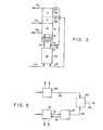
- FIG. 2 illustrates a conventional oxygen-only plant column section.
- the plant is composed of a high pressure column 50 combined with a low pressure column 51.
- the two columns are joined by main condenser 52.
- the high pressure air enters the lower column at 53 and is separated into a'high nitrogen content vapor stream 54 and a high oxygen content stream 58.
- Stream 54 is condensed in condenser 52 and exits that unit as a liquid stream 55. That liquid stream is split into two portions.
- One portion 57 is used as reflux for the high pressure column whereas the other portion 56 is transferred to the top of the low pressure column after expansion through valve 60.
- the high oxygen content fraction 58 is expanded through valve 59 at a lower point in the low pressure column.
- low pressure air 62 is fed to the upper column.
- This low pressure air 62 is fed to the upper column.
- This low pressure air 62 or turbine air fraction is that fraction of the feed air which is turbine expanded within the heat exchanger portion of the plant to develop refrigeration for the air plant. All three feeds in the low pressure column, the two liquid feeds and the one vapor are separated into two streams.
- the one stream 63 becomes the product oxygen stream and is drawn from the bottom of the low pressure column whereas the other stream 61 is then the waste stream and is taken from the top of the column.
- Heat exchangers may subcool the liquid reflux streams between the high pressure and low pressure columns.
- the column configuration is for an oxygen-only type air separation plant, that is, the intended product of the plant is gas oxygen at a high purity as normally required for industrial operations. It can be seen that this column section arrangement uses three sections for the upper column I, II and III and one section for the lower column IV.
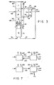
- FIG. 3 A conventional column arrangement utilized for an oxygen and argon producing air separation plant is illustrated in Figure 3. As can be seen from Figure 3, this arrangement employs a high pressure column 70 combined with a low pressure column 71 and joined by a condenser unit 74. The addition required to produce an argon product is a crude argon column 72. The high pressure air 75 enters the bottom of the lower column and progresses through a tray section so that high nitrogen content vapor stream 77 enters heat exchanger 74 and exits as condensed liquid 78. The condensed liquid stream is split into two portions, one returned as reflux 79 for the high pressure column whereas the other 80 is transferred as reflux to the top of the low pressure column.
- the high nitrogen content reflux stream is expanded through valve 81 into the top of the upper column as for the oxygen-only plant
- the high oxygen reflux stream from the bottom of the high pressuree column is transferred to condenser 73 at the top of the crude argon column. It is expanded through valve 89 and partially evaporated in condenser 73 prior to being introduced into the low pressure column as stream 88 as a liquid and vapor mixture.
- the low pressure column has a low pressure air feed 83 which is that fraction of the air utilized for plant refrigeration.
- the low pressure column is modified compared to the oxygen-only situation in that it has two additional feed points between that low pressure air stream 83 and the product oxygen stream 84.
- a vapor feed stream 85 is drawn from the low pressure column and fed to the bottom of the crude argon column 72 where it is enriched to high argon content at the top of the column 72. At the top of that column, some of this vapor is condensed in the unit 73 to serve as reflux for the column whereas the remaining fraction of the vapor is drawn as a crude argon product 87.
- the reflux stream continues down the bottom of the column 72 and is then re-introduced to the low pressure column as stream 86.
- the system produces a product oxygen stream 84 from the low pressure column, a crude argon product 87 from the argon column and a waste stream 82 from the top of the low pressure column.
- This arrangement requires a four section low pressure column, I, II, III and IV and a one section high pressure column V in addition to another single section VI argon column.
- This conventional oxygen-argon column configuration allows separation of the air feed into oxygen and argon products employing only internal process streams and is an effective separation system.
- the crude argon product 87 produced from the conventional oxygen-argon column arrangement can be refined as illustrated in Figure 4.
- the crude argon stream 107 is warmed in exchanger 100 to am ambient temperature low pressure condition as at 108. This low pressure vapor is then compressed by compressor 101 and cooled by water cooler (not shown) so that it is in a high pressure ambient condition at 109.
- small hydrogen stream 110 is added and the combined hydrogen crude product stream 111 is introduced into a catalytic reactor 102.
- the hydrogen and oxygen content of the crude argon product is reacted so that existing stream 112 contains no free oxygen but is instead moisture containing. That moisture is then removed in drier 103 so that stream 113 contains only argon and nitrogen (and perhaps some excess hydrogen).
- That stream is then cooled in exchanger 100 so that the - cold high pressure stream 114 is then condensed in condenser 106 and the liquid 115 is expanded through valve 116 and passed through conduit 117 as feed to a nitrogen rejection column 104.
- This column is refrigerated at the top by liquid nitrogen 118 which is transferred in condenser 105 to cold nitrogen gas 119.
- the combination of the argon nitrogen stream condensing at the bottom of the column 104 and the liquid nitrogen refrigeration at the top serves to drive the column so that the nitrogen is rejected at 120 and liquid argon at high purity can be removed at the bottom of the column as stream 121.
- FIG. 5 shows the addition of the auxiliary column argon recovery process and apparatus of this invention at a plant location that combines an existing oxygen-only air separation plant 131 and existing oxygen-argon air separation plant 130.
- the capability of the auxiliary column system of this invention to produce crude argon 135 at essentially the same purity specifications as the conventional argon plant allows a central or common argon refinery for both plants.
- the crude argon 135 from the auxiliary column can be combined with the crude argon 134 from the oxygen-argon plant and processed in a common argon refinery 133 to produce refined argon 136 product.
- auxiliary argon recovery process is attractive in that it allows the use of a conventional argon refining system or allows the use of existing argon refinery as may already be available with an exisitng oxygen-argon plant at the same location wherein an oxygen-only plant is to be coverted to recover argon.
- Another advantage of the improved process of this invention is illustrated schematically in Figure 5. As shown, the only two streams joining the main existing oxygen-only plant 131 and the auxiliary argon column 132 are the feed stream 137 and the oxygen product return stream 138. This feature of minimal process stream connection between the existing oxygen-only plant and the auxiliary argon recovery unit is an extremely convenient feature of this invention.
- FIG. 6 This figure shows that the retrofit argon recovery process has considerable flexibility relative to refrigeration source.
- the process arrangement shown on Figure 6A utilizes liquid nitrogen for refrigeration of the argon column.
- the main air separation plant 140 is connected to the auxiliary column feed stream 142 and return oxygen stream 143.
- the liquid nitrogen refrigerant 145 is added to the top condenser of the auxiliary column and is returned with stream 146 through exchanger 148.
- the warm nitrogen stream 150 includes the nitrogen in the heat pump circuit and that due to the liquid nitrogen refrigerant addition.
- nitrogen could be vented as at 149 with the remaining nitrogen 151 being compressed by compressor 153 and then returned at high pressure as stream 152.
- That stream is cooled and enters as cold high pressure nitrogen 147 which comprises the nitrogen flow required to drive the auxiliary column.
- the auxiliary argon column produces a crude argon stream 144 suitable for further processing in a conventional argon refining system.
- the nitrogen vent 149 is dependent on the relationship-between the liquid nitrogen refrigeration needed and the leakage of associated argon recovery equipment. Since all practical equipment does have some loss of fluid when pressurized, it would be expected that stream 149 to be vented would be somewhat less than the refrigerant stream 145 added to the auxiliary system.
- addition of the liquid nitrogen to the top condenser is preferred practice, it is acceptable to add the liquid at another point. For example, actual process piping restrictions may make it desirable to add the liquid between the top condenser and the heat pump recycle heat exchanger.
- FIG. 6B Another option relative to refrigeration for the auxiliary argon column unit is illustrated schematically in Figure 6B.
- This illustration shows the main plant 160 connected to auxiliary argon column 170 by feed stream 171 and oxygen return stream 172.
- the argon column is refrigerated by the addition of liquid oxygen 173 to the bottom condenser of the auxiliary argon column. This liquid when vaporized to counteract the heat leakage then returns as oxygen product stream 172.
- the auxiliary argon column produces crude argon 174 suitable for further processing.
- the oxygen return 172 is the sum of that obtained from the feed stream 171 and the vaporized refrigerant stream 173.
- the heat pump circuit including exchanger 177 and compressor 181 includes cold nitrogen vapor 175 exiting from the column warmed in the exchanger to warm condition 178. Then nitrogen make-up 179 is added so that combined stream 180 is compressed to the high-pressure, high-temperature condition 182. Following the water cooler, the high presure ambient temperature stream 183 is then cooled to high pressure cold condition 176 entering the condenser of the auxiliary argon column. Nitrogen makeup 179 would be required to counterbalance equipment leakage within the nitrogen heat pump circuit. The nitrogen make-up stream 179 would be required to counterbalance equipment leakage within the nitrogen heat pump circuit. The nitrogen make-up stream 179 can be obtained from any convenient source, such as a pressurized nitrogen pipeline within the plant complex, or as part of any available nitrogen stream from the main air separation plant.
- FIG. 6C schematically shows still another refrigeration option for the auxiliary argon column.
- Main plant 190 is connected to auxiliary argon column 191 by feed stream 192 and oxygen return stream 193.
- the crude argon 196 is sent for further processing in a conventional argon refining system.
- This refrigeration option does not use liquid addition to the auxiliary argon column; instead it uses a turbine expansion of circulating fluid incorporated with the heat pump loop.
- Nitrogen is compressed by compressor 205 to yield a high pressure, high temperature nitrogen stream 206 which is cooled in a water cooler to a high pressure ambient condition as in 207.
- This stream is partially cooled in exchanger 201 and then a portion of that stream 200 is removed from the exchanger and expanded 199 to produce a low temperature stream 198.
- the remaining high pressure nitrogen stream is cooled and enter as stream 195 to the condenser of the auxiliary argon column. Within the column this stream drives the bottom boiler and top condenser and exits as a low pressure cold stream 194.
- the cold stream from the expander is added to this stream and the combined stream 197 is then rewarmed in exchanger 201 to ambient temperature 202.
- Nitrogen make-up stream 203 is added to counterbalance equipment leakage losses and then the combined low pressure stream 204 is passed to the compressor for another circuit.
- the system refrigeration is produced by the turbine expansion of stream 200 and necessary refrigeration for the column is transferred to the column by refrigeration exchange between streams 197 and 195, that is, stream 195 is cooled further than it would be if stream 198 were not added to the return nitrogen stream.
- any of the three options is a suitable means of refrigerating the auxiliary argon column and the choice is within the competence of one skilled in this art.
- the flexibility of the improved process of this invention relative to the feed condition is illustrated schematically in Figure 7.
- the preferred arrangement utilizes the combination of the main air separation plant 220 and the auxiliary argon column 226 connected by vapor feed 221 and a . vapor oxygen return stream 222.
- the argon column can use refrigerant stream 223 and involve a vent nitrogen stream 224 and a crude argon product 225. It is possible for the argon column to utilize a liquid feed.
- main plant 230 is combined with argon column 231 via liquid fed 232.
- This liquid feed has a similar compositon as the gas feed but would then be separated into a liquid oxygen fraction 235 and a crude argon fraction 234 which may or may not be liquid depending on the addition of liquid nitrogen refrigerant 233.
- the crude argon fraction could be produced as liquid if sufficient liquid nitrogen refrigerant 233 and thereby vent gas 236 were added.
- the liquid feed connection illustrated would apply in that situation where the main oxygen-only plant was normally a liquid oxygen producer. Hence, this would mean that the additional feed stream transferred to the add-on argon package would be liquid also and would not upset the refrigeration balance of the main air separation plant.
- argon column feed For a typical air plant processing about two million cu. ft. of air per hour (56600 m 3 /hr) a conventional system requires an argon column feed of about 442,000 cfh (12,509 m 3 /hr) to produce the crude argon product.
- the argon product typically contains about 97.5% argon and about 1-1/2% oxygen and 1% nitrogen.
- the argon product purity specifications are such that the crude product can be readily upgraded to refined product in a conventional argon refinery.
- the argon column feed is about 114,000 cfh (3226 m 3 /hr) for similar air feed, or only about 1/4 of that required in the conventional arrangement.
- the auxiliary column can produce 98,400 cfh (2785 m 3 /hr) of oxygen product at required purity of 99.5% oxygen and a crude argon product of 15,600 cfh (442 m 3 /hr).
- Argon product purity conditions are essentially the same as that of the conventional argon column.
- the oxygen and argon recovery is comparable to the conventional plant.
- the Pollitzer-et al. additional argon column as driven by the high pressure column nitrogen vapor also'processes a feed stream taken from the low pressure column of the main plant.
- This stream of again about 114,000 cfh (3226 m 3 /hr) is in a liquid condition and results in producing about 103,700 cfh (2935 m 3 /hr) of liquid oxygen product from the auxiliary column and about 10,300 cfh (292 m 3 /hr) of vapor crude argon product.
- the crude argon product purity may be marginally acceptable for further processing in a conventional refining system, although the nitrogen content of 3.8% would tax the nitrogen rejection section of the refinery.
- Table II Another advantage of the auxiliary argon column process is illustrated in Table II.
- Table II This table summarizes a computer simulation of the performance of a conventional oxygen-argon plant and one employing the process and apparatus of this invention for equivalent plant upsets.
- the table tabulates the expected purities for feed and product streams associated with the argon column for the two processes as a function of liquid reflux changes.
- the base case is the situation expected with steady plant operation.
- the two other cases labeled 1% reflux decrease and 1% reflux increase illustrate the situation related to plant operating variations due to either normal plant changes or unexpected changes.
- conventional air plants often utilize reversing heat exchangers for contaminant removal and thereby periodically reverse flow in the heat exchangers which causes a flow upset for the columns.
- the auxiliary column system of this invention has the significant advantage of minimizing purity variations around the system as a function of plant operational upsets and thereby is expected to be able to remain in production under conditions where the conventional column would need to stop operation.
- the auxiliary argon column process and apparatus of this invention has the advantages of comparable product recovery relative to a conventional argon plant, improved stability of operation, flexibility at existing plant locations, and ease of plant retrofits.
- the auxiliary argon column process and apparatus of this invention is a significant advance for argon retrofit systems.
Landscapes
- Engineering & Computer Science (AREA)
- Physics & Mathematics (AREA)
- Mechanical Engineering (AREA)
- Thermal Sciences (AREA)
- General Engineering & Computer Science (AREA)
- Chemical & Material Sciences (AREA)
- Chemical Kinetics & Catalysis (AREA)
- Separation By Low-Temperature Treatments (AREA)
- Oxygen, Ozone, And Oxides In General (AREA)
- Separation Using Semi-Permeable Membranes (AREA)
- Sampling And Sample Adjustment (AREA)
Priority Applications (1)
| Application Number | Priority Date | Filing Date | Title |
|---|---|---|---|
| AT82850252T ATE31450T1 (de) | 1981-12-08 | 1982-12-07 | Verfahren und apparat zur rekuperation von argon aus einer lufttrennungsanlage fuer die alleinige herstellung von sauerstoff. |
Applications Claiming Priority (2)
| Application Number | Priority Date | Filing Date | Title |
|---|---|---|---|
| US06/328,631 US4433990A (en) | 1981-12-08 | 1981-12-08 | Process to recover argon from oxygen-only air separation plant |
| US328631 | 1982-12-08 |
Publications (3)
| Publication Number | Publication Date |
|---|---|
| EP0081472A2 true EP0081472A2 (fr) | 1983-06-15 |
| EP0081472A3 EP0081472A3 (en) | 1984-12-27 |
| EP0081472B1 EP0081472B1 (fr) | 1987-12-16 |
Family
ID=23281744
Family Applications (1)
| Application Number | Title | Priority Date | Filing Date |
|---|---|---|---|
| EP82850252A Expired EP0081472B1 (fr) | 1981-12-08 | 1982-12-07 | Procédé et dispositif pour récupérer de l'argon d'une installation de séparation de l'air destinée pour l'unique production de l'oxygène |
Country Status (14)
| Country | Link |
|---|---|
| US (1) | US4433990A (fr) |
| EP (1) | EP0081472B1 (fr) |
| JP (1) | JPS58193080A (fr) |
| KR (1) | KR880001510B1 (fr) |
| AT (1) | ATE31450T1 (fr) |
| AU (1) | AU548767B2 (fr) |
| BR (1) | BR8207084A (fr) |
| CA (1) | CA1172157A (fr) |
| DE (1) | DE3277847D1 (fr) |
| DK (1) | DK542282A (fr) |
| ES (1) | ES8404957A1 (fr) |
| MX (1) | MX157938A (fr) |
| NO (1) | NO824107L (fr) |
| ZA (1) | ZA828994B (fr) |
Cited By (3)
| Publication number | Priority date | Publication date | Assignee | Title |
|---|---|---|---|---|
| EP0528331A1 (fr) * | 1991-08-12 | 1993-02-24 | Praxair Technology, Inc. | Système de rectification cryogénique pour la production améliorée d'argon |
| EP0556503A1 (fr) * | 1992-02-13 | 1993-08-25 | Air Products And Chemicals, Inc. | Evaporation de l'oxygène liquide avec le but d'une récupération améliorée de l'argon |
| EP0558082A1 (fr) * | 1992-02-27 | 1993-09-01 | Praxair Technology, Inc. | Procédé de rectification cryogénique en utilisant une pompe de chaleur d'argon |
Families Citing this family (23)
| Publication number | Priority date | Publication date | Assignee | Title |
|---|---|---|---|---|
| US4615716A (en) * | 1985-08-27 | 1986-10-07 | Air Products And Chemicals, Inc. | Process for producing ultra high purity oxygen |
| US4617036A (en) * | 1985-10-29 | 1986-10-14 | Air Products And Chemicals, Inc. | Tonnage nitrogen air separation with side reboiler condenser |
| GB8610766D0 (en) * | 1986-05-02 | 1986-06-11 | Colley C R | Yield of krypton xenon in air separation |
| US4715874A (en) * | 1986-09-08 | 1987-12-29 | Erickson Donald C | Retrofittable argon recovery improvement to air separation |
| US4732580A (en) * | 1986-10-01 | 1988-03-22 | The Boc Group, Inc. | Argon and nitrogen coproduction process |
| US4780118A (en) * | 1987-07-28 | 1988-10-25 | Union Carbide Corporation | Process and apparatus to produce ultra high purity oxygen from a liquid feed |
| US4755202A (en) * | 1987-07-28 | 1988-07-05 | Union Carbide Corporation | Process and apparatus to produce ultra high purity oxygen from a gaseous feed |
| US4775399A (en) * | 1987-11-17 | 1988-10-04 | Erickson Donald C | Air fractionation improvements for nitrogen production |
| US4838913A (en) * | 1988-02-10 | 1989-06-13 | Union Carbide Corporation | Double column air separation process with hybrid upper column |
| US4822395A (en) * | 1988-06-02 | 1989-04-18 | Union Carbide Corporation | Air separation process and apparatus for high argon recovery and moderate pressure nitrogen recovery |
| US4838785A (en) * | 1988-07-05 | 1989-06-13 | Cameron Forge Company | Walking beam furnace insulation |
| US4987744A (en) * | 1990-01-26 | 1991-01-29 | Union Carbide Industrial Gases Technology Corporation | Cryogenic distillation with unbalanced heat pump |
| US5133790A (en) * | 1991-06-24 | 1992-07-28 | Union Carbide Industrial Gases Technology Corporation | Cryogenic rectification method for producing refined argon |
| US5235816A (en) * | 1991-10-10 | 1993-08-17 | Praxair Technology, Inc. | Cryogenic rectification system for producing high purity oxygen |
| US5245832A (en) * | 1992-04-20 | 1993-09-21 | Praxair Technology, Inc. | Triple column cryogenic rectification system |
| US5305611A (en) * | 1992-10-23 | 1994-04-26 | Praxair Technology, Inc. | Cryogenic rectification system with thermally integrated argon column |
| GB9500514D0 (en) * | 1995-01-11 | 1995-03-01 | Boc Group Plc | Air separation |
| US7003359B2 (en) * | 2001-08-17 | 2006-02-21 | Air Products And Chemicals, Inc. | Multiple process plant product lines from a common set of engineered components |
| NL1020137C2 (nl) * | 2002-03-11 | 2003-09-12 | Stichting Energie | Werkwijze en inrichting voor het scheiden van gassen en/of vloeistoffen. |
| US20090320520A1 (en) * | 2008-06-30 | 2009-12-31 | David Ross Parsnick | Nitrogen liquefier retrofit for an air separation plant |
| FR2947621A1 (fr) * | 2009-07-06 | 2011-01-07 | Air Liquide | Appareil de separation de gaz de l'air par distillation cryogenique et procede de modification d'un tel appareil |
| FR3013820A1 (fr) * | 2013-11-27 | 2015-05-29 | Air Liquide | Procede et appareil de separation cryogenique d’un gaz de synthese contenant de l’hydrogene, de l’azote et du monoxyde de carbone |
| AU2018269511A1 (en) | 2017-05-16 | 2019-11-28 | Terrence J. Ebert | Apparatus and process for liquefying gases |
Citations (2)
| Publication number | Priority date | Publication date | Assignee | Title |
|---|---|---|---|---|
| US2700282A (en) * | 1948-02-12 | 1955-01-25 | British Oxygen Co Ltd | Fractional separation of air |
| FR2305701A1 (fr) * | 1975-03-26 | 1976-10-22 | Siad | Procede et appareil de recuperation d'argon dans un processus de fractionnement de l'air |
Family Cites Families (9)
| Publication number | Priority date | Publication date | Assignee | Title |
|---|---|---|---|---|
| US1638005A (en) | 1921-08-12 | 1927-08-02 | L Air Liquide Soc | Process of separation of the elements of air or of other gaseous mixtures by liquefaction and rectification |
| NL30531C (fr) | 1930-02-07 | |||
| US2545462A (en) | 1948-03-17 | 1951-03-20 | Koppers Co Inc | System for separation of argon from air |
| US2547177A (en) | 1948-11-02 | 1951-04-03 | Linde Air Prod Co | Process of and apparatus for separating ternary gas mixtures |
| BE495886A (fr) | 1949-06-20 | |||
| FR2041701B1 (fr) | 1969-05-05 | 1974-02-01 | Air Liquide | |
| US4137056A (en) | 1974-04-26 | 1979-01-30 | Golovko Georgy A | Process for low-temperature separation of air |
| JPS5241235A (en) * | 1976-07-15 | 1977-03-30 | Ajinomoto Co Inc | Fungicidal composition for agricultural and gardening use |
| JPS6044585B2 (ja) * | 1978-02-10 | 1985-10-04 | 株式会社日立製作所 | アルゴンの分離方法およびその装置 |
-
1981
- 1981-12-08 US US06/328,631 patent/US4433990A/en not_active Expired - Fee Related
-
1982
- 1982-10-29 CA CA000414552A patent/CA1172157A/fr not_active Expired
- 1982-12-06 BR BR8207084A patent/BR8207084A/pt not_active IP Right Cessation
- 1982-12-06 KR KR8205464A patent/KR880001510B1/ko active
- 1982-12-07 DE DE8282850252T patent/DE3277847D1/de not_active Expired
- 1982-12-07 AT AT82850252T patent/ATE31450T1/de not_active IP Right Cessation
- 1982-12-07 NO NO824107A patent/NO824107L/no unknown
- 1982-12-07 DK DK542282A patent/DK542282A/da not_active Application Discontinuation
- 1982-12-07 EP EP82850252A patent/EP0081472B1/fr not_active Expired
- 1982-12-07 AU AU91616/82A patent/AU548767B2/en not_active Ceased
- 1982-12-07 ZA ZA828994A patent/ZA828994B/xx unknown
- 1982-12-07 ES ES517980A patent/ES8404957A1/es not_active Expired
- 1982-12-07 MX MX195485A patent/MX157938A/es unknown
- 1982-12-07 JP JP57213484A patent/JPS58193080A/ja active Granted
Patent Citations (2)
| Publication number | Priority date | Publication date | Assignee | Title |
|---|---|---|---|---|
| US2700282A (en) * | 1948-02-12 | 1955-01-25 | British Oxygen Co Ltd | Fractional separation of air |
| FR2305701A1 (fr) * | 1975-03-26 | 1976-10-22 | Siad | Procede et appareil de recuperation d'argon dans un processus de fractionnement de l'air |
Cited By (3)
| Publication number | Priority date | Publication date | Assignee | Title |
|---|---|---|---|---|
| EP0528331A1 (fr) * | 1991-08-12 | 1993-02-24 | Praxair Technology, Inc. | Système de rectification cryogénique pour la production améliorée d'argon |
| EP0556503A1 (fr) * | 1992-02-13 | 1993-08-25 | Air Products And Chemicals, Inc. | Evaporation de l'oxygène liquide avec le but d'une récupération améliorée de l'argon |
| EP0558082A1 (fr) * | 1992-02-27 | 1993-09-01 | Praxair Technology, Inc. | Procédé de rectification cryogénique en utilisant une pompe de chaleur d'argon |
Also Published As
| Publication number | Publication date |
|---|---|
| BR8207084A (pt) | 1983-10-11 |
| JPS58193080A (ja) | 1983-11-10 |
| AU9161682A (en) | 1983-06-16 |
| ES517980A0 (es) | 1984-05-16 |
| JPS6214750B2 (fr) | 1987-04-03 |
| NO824107L (no) | 1983-06-09 |
| AU548767B2 (en) | 1986-01-02 |
| CA1172157A (fr) | 1984-08-07 |
| US4433990A (en) | 1984-02-28 |
| EP0081472A3 (en) | 1984-12-27 |
| MX157938A (es) | 1988-12-23 |
| KR840002975A (ko) | 1984-07-21 |
| ZA828994B (en) | 1983-09-28 |
| DK542282A (da) | 1983-06-09 |
| EP0081472B1 (fr) | 1987-12-16 |
| DE3277847D1 (en) | 1988-01-28 |
| KR880001510B1 (ko) | 1988-08-16 |
| ES8404957A1 (es) | 1984-05-16 |
| ATE31450T1 (de) | 1988-01-15 |
Similar Documents
| Publication | Publication Date | Title |
|---|---|---|
| US4433990A (en) | Process to recover argon from oxygen-only air separation plant | |
| US4453957A (en) | Double column multiple condenser-reboiler high pressure nitrogen process | |
| US5440884A (en) | Cryogenic air separation system with liquid air stripping | |
| US4560397A (en) | Process to produce ultrahigh purity oxygen | |
| EP0556516B1 (fr) | Cycles de séparation d'air à rebouilleur, à colonne double, à pression élevée et leur intégration dans des turbines à gaz | |
| US4664686A (en) | Process to separate nitrogen and methane | |
| US5655388A (en) | Cryogenic rectification system for producing high pressure gaseous oxygen and liquid product | |
| US5251451A (en) | Multiple reboiler, double column, air boosted, elevated pressure air separation cycle and its integration with gas turbines | |
| US4448595A (en) | Split column multiple condenser-reboiler air separation process | |
| US5392609A (en) | Process and apparatus for the production of impure oxygen | |
| EP0637725A1 (fr) | Système de rectification cryogénique pour opération à pression plus basse | |
| EP0841524B1 (fr) | Système de rectification cryogénique avec colonne de liquide de cuve | |
| US5469710A (en) | Cryogenic rectification system with enhanced argon recovery | |
| US5233838A (en) | Auxiliary column cryogenic rectification system | |
| EP0594214B1 (fr) | Procédé de rectification cryogénique intégré thermiquement à une colonne d'argon | |
| US5263327A (en) | High recovery cryogenic rectification system | |
| US5611219A (en) | Air boiling cryogenic rectification system with staged feed air condensation | |
| US5582033A (en) | Cryogenic rectification system for producing nitrogen having a low argon content | |
| US5666824A (en) | Cryogenic rectification system with staged feed air condensation | |
| US5682765A (en) | Cryogenic rectification system for producing argon and lower purity oxygen | |
| US5832748A (en) | Single column cryogenic rectification system for lower purity oxygen production | |
| US6073462A (en) | Cryogenic air separation system for producing elevated pressure oxygen |
Legal Events
| Date | Code | Title | Description |
|---|---|---|---|
| PUAI | Public reference made under article 153(3) epc to a published international application that has entered the european phase |
Free format text: ORIGINAL CODE: 0009012 |
|
| AK | Designated contracting states |
Designated state(s): AT BE CH DE FR GB IT LI LU NL SE |
|
| 17P | Request for examination filed |
Effective date: 19831201 |
|
| PUAL | Search report despatched |
Free format text: ORIGINAL CODE: 0009013 |
|
| AK | Designated contracting states |
Designated state(s): AT BE CH DE FR GB IT LI LU NL SE |
|
| 17Q | First examination report despatched |
Effective date: 19860129 |
|
| R17C | First examination report despatched (corrected) |
Effective date: 19860811 |
|
| ITF | It: translation for a ep patent filed |
Owner name: BARZANO' E ZANARDO ROMA S.P.A. |
|
| GRAA | (expected) grant |
Free format text: ORIGINAL CODE: 0009210 |
|
| AK | Designated contracting states |
Kind code of ref document: B1 Designated state(s): AT BE CH DE FR GB IT LI LU NL SE |
|
| PG25 | Lapsed in a contracting state [announced via postgrant information from national office to epo] |
Ref country code: NL Effective date: 19871216 Ref country code: LI Effective date: 19871216 Ref country code: CH Effective date: 19871216 Ref country code: AT Effective date: 19871216 |
|
| REF | Corresponds to: |
Ref document number: 31450 Country of ref document: AT Date of ref document: 19880115 Kind code of ref document: T |
|
| PG25 | Lapsed in a contracting state [announced via postgrant information from national office to epo] |
Ref country code: SE Effective date: 19871231 |
|
| REF | Corresponds to: |
Ref document number: 3277847 Country of ref document: DE Date of ref document: 19880128 |
|
| ET | Fr: translation filed | ||
| REG | Reference to a national code |
Ref country code: CH Ref legal event code: PL |
|
| NLV1 | Nl: lapsed or annulled due to failure to fulfill the requirements of art. 29p and 29m of the patents act | ||
| PG25 | Lapsed in a contracting state [announced via postgrant information from national office to epo] |
Ref country code: LU Free format text: LAPSE BECAUSE OF NON-PAYMENT OF DUE FEES Effective date: 19881231 |
|
| PGFP | Annual fee paid to national office [announced via postgrant information from national office to epo] |
Ref country code: DE Payment date: 19910919 Year of fee payment: 10 |
|
| PGFP | Annual fee paid to national office [announced via postgrant information from national office to epo] |
Ref country code: GB Payment date: 19910923 Year of fee payment: 10 |
|
| PGFP | Annual fee paid to national office [announced via postgrant information from national office to epo] |
Ref country code: FR Payment date: 19910924 Year of fee payment: 10 |
|
| PGFP | Annual fee paid to national office [announced via postgrant information from national office to epo] |
Ref country code: BE Payment date: 19911024 Year of fee payment: 10 |
|
| PLBE | No opposition filed within time limit |
Free format text: ORIGINAL CODE: 0009261 |
|
| STAA | Information on the status of an ep patent application or granted ep patent |
Free format text: STATUS: NO OPPOSITION FILED WITHIN TIME LIMIT |
|
| 26N | No opposition filed | ||
| ITTA | It: last paid annual fee | ||
| PG25 | Lapsed in a contracting state [announced via postgrant information from national office to epo] |
Ref country code: GB Effective date: 19921207 |
|
| PG25 | Lapsed in a contracting state [announced via postgrant information from national office to epo] |
Ref country code: BE Effective date: 19921231 |
|
| BERE | Be: lapsed |
Owner name: UNION CARBIDE CORP. Effective date: 19921231 |
|
| GBPC | Gb: european patent ceased through non-payment of renewal fee |
Effective date: 19921207 |
|
| PG25 | Lapsed in a contracting state [announced via postgrant information from national office to epo] |
Ref country code: FR Effective date: 19930831 |
|
| PG25 | Lapsed in a contracting state [announced via postgrant information from national office to epo] |
Ref country code: DE Effective date: 19930901 |
|
| REG | Reference to a national code |
Ref country code: FR Ref legal event code: ST |