EP0081214A1 - Guide apparatus - Google Patents
Guide apparatus Download PDFInfo
- Publication number
- EP0081214A1 EP0081214A1 EP82111210A EP82111210A EP0081214A1 EP 0081214 A1 EP0081214 A1 EP 0081214A1 EP 82111210 A EP82111210 A EP 82111210A EP 82111210 A EP82111210 A EP 82111210A EP 0081214 A1 EP0081214 A1 EP 0081214A1
- Authority
- EP
- European Patent Office
- Prior art keywords
- jaw
- annular rail
- cylindrical member
- rail
- guide apparatus
- Prior art date
- Legal status (The legal status is an assumption and is not a legal conclusion. Google has not performed a legal analysis and makes no representation as to the accuracy of the status listed.)
- Granted
Links
Images


Classifications
-
- G—PHYSICS
- G21—NUCLEAR PHYSICS; NUCLEAR ENGINEERING
- G21C—NUCLEAR REACTORS
- G21C17/00—Monitoring; Testing ; Maintaining
- G21C17/017—Inspection or maintenance of pipe-lines or tubes in nuclear installations
-
- G—PHYSICS
- G21—NUCLEAR PHYSICS; NUCLEAR ENGINEERING
- G21C—NUCLEAR REACTORS
- G21C17/00—Monitoring; Testing ; Maintaining
- G21C17/003—Remote inspection of vessels, e.g. pressure vessels
- G21C17/007—Inspection of the outer surfaces of vessels
-
- G—PHYSICS
- G01—MEASURING; TESTING
- G01N—INVESTIGATING OR ANALYSING MATERIALS BY DETERMINING THEIR CHEMICAL OR PHYSICAL PROPERTIES
- G01N2291/00—Indexing codes associated with group G01N29/00
- G01N2291/26—Scanned objects
- G01N2291/263—Surfaces
- G01N2291/2634—Surfaces cylindrical from outside
-
- Y—GENERAL TAGGING OF NEW TECHNOLOGICAL DEVELOPMENTS; GENERAL TAGGING OF CROSS-SECTIONAL TECHNOLOGIES SPANNING OVER SEVERAL SECTIONS OF THE IPC; TECHNICAL SUBJECTS COVERED BY FORMER USPC CROSS-REFERENCE ART COLLECTIONS [XRACs] AND DIGESTS
- Y02—TECHNOLOGIES OR APPLICATIONS FOR MITIGATION OR ADAPTATION AGAINST CLIMATE CHANGE
- Y02E—REDUCTION OF GREENHOUSE GAS [GHG] EMISSIONS, RELATED TO ENERGY GENERATION, TRANSMISSION OR DISTRIBUTION
- Y02E30/00—Energy generation of nuclear origin
- Y02E30/30—Nuclear fission reactors
Definitions
- the first jaw means 55 incorporates a ratchet gearing system.
- a tongue-like jaw 56 is adjustable to follow a change of the outer diameter of the structure to be inspected by the combination of a rotatable ratchet 57 fixed to the jaw 57 and a pawl means 58 engageable with the ratchet 57.
Abstract
Description
- The present invention relates to a guide aparatus, and more particularly to a guide apparatus having rail means adapted to run a processing device along over the outer peripheral surface of a cylindrical structure to be processed and to hold the same at predetermined positions over the outer peripheral surfac of the structure. Still more particularly, the present invention is concerned with a guide appaatus suitable for use in examination of nozzles and pipes associated with a nuclear reactor.
-
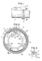
- Fig. 1 is an illustration of a conventional guide apparatus attached to a pipe;
- Fig. 2 is a sectional view taken along the line II-II in Fig. 1, without driving means;
- Fig. 3 is a sectional view taken along the line III-III of Fig. 2;
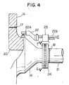
- Fig. 4 is an illustration of an embodiment of the present invention attached to a nozzle;
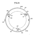
- Fig. 5 is a sectional view taken along the line V-V of Fig. 4, without driving means;
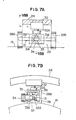
- Fig. 6 is a plan view of a first jaw means incorporated in the embodiment shown in Fig. 4;
- Fig. 7A is a side elevational view of the jaw means shown in Fig. 6;
- Fig. 7B is a sectional view taken along the line VIIB-VIIB in Fig. 7A;
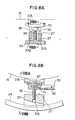
- Fig. 8A is a detailed partial sectional view of the second jaw means incorporated in the embodiment shown in Fig. 4;
- Fig. 8B is a sectional view taken along the line VIIIB-VIIIB in Fig. 8A;
- Fig. 9 is a side elevational view of a handle shown in Fig. 8B;
- Fig. 10 is a sectional view taken along the line X-X in Fig. 9;
- Fig. 11A is a sectional view of a handle portion shown in Fig. 5 taken along the line XI A - XI A in Fig. 11B ;
- Fig. 11B is a plan view of the handle portion shown in Fig. 11A;
- Fig. 11C is a sectional view showing the handle portion in the locked state;
- Fig. 12 is a sectional view of a first jaw means incorporated in another embodiment; and
- Fig. 13 is a sectional view of a first jaw means incorporated in still another embodiment.
- In order to maintain nozzles or pipes associated with a nuclear reactor in good conditions, non-destructive inspection utilizing supersonic waves is conducted periodically to find out any defective part which is to be repaired or renewed without delay. In order to achieve a higher efficiency of the periodical inspection work, a remote control inspection system now has been in use in place of the conventional manual inspection system.
- Generally speaking, for automatically conducting the non-destructive inspection utilizing supersonic waves to a member having a cylindrical surface, e.g. the aforementioned nozzle or pipe, the inspecting means is run by a driving means along on an annular rail means coaxially arranged around over the member to be inspected, so that the outer peripheral surface of the member is scanned along the axial direction and the circumferential direction by a probe of the inspecting means. The position of the defective portion requiring repair or renewal is precisely detected by means of the maintenance of a good reproducibility of the inspection, as well as good running conditions of the inspecting means.
- A nuclear reactor has pipes and nozzles associated therewith of different diameters. In addition, nozzles or pipes of the same diameter are used on various portions of the nuclear reactor. In general, therefore, the annular rail means is designed to be mounted removably on such nozzle or pipe so as to remove it from the nozzle or pipe when the inspection is not made. The removable mounting of the annular rail means is also preferred for the reason that the permanent mounting of the rail means undesirably increases the outer diameter of the nozzle or pipe to waste a space because the nozzle or pipe is usually wrapped by a heat insulator.
- Figs. 1 to 3 show an example of the conventional guide apparatus. Referring first to Fig. 1, an annular rail means 4 coaxially mounted on a
pipe 1 is provided with adriving means 3 for guiding and driving the inspecting means having aprobe 2 to a portion of thepipe 1 to be inspected. - As roughly shown in Figs. 2 and 3, the
annular rail 4 is composed of twosemi-circular rail halves rail halves pipe 1 and is then locked by alock handle 6 to complete a continuousannular rail 4. At the inner side .of the annular rail, a flexible shaft havingserial shaft pieces 9A to 9C is connected to an operating end of amanipulation handle 7 through a ratchet mechanism 8. Theshaft pieces 9A to 9C are adapted to be rotated by the circumferential reciprocative operation of thehandle 7, i.e. the movement in the directions of the arrows A and B. The rotation of theshaft piece 9A causes a rotation of a right andleft screw 10 which is attached to theshaft piece 9A and which is provided with a right-threaded portion and left-threaded portion, so thatmovable elements 11 screw mounted on these threaded portions are moved on thescrew 10 toward and away from each other.Arms 12 pivotted at their one ends to themovable elements 11 and abar 13 pivoted at its opposite ends to the other ends of botharms 12 compose a link mechanism. The inclination angles of thearms 12 are changed as a result of the movement of themovable elements 11 to cause a movement of thebar 13. Consequently, Amovable jaw 14A connected to thebar 13 is swung about apivot 14 which is pivotally mounted on theshaft piece 9A, so that a free end of themovable jaw 14A is displaced toward the center of the annular rail. The rotation of theshaft piece 9A is transmitted toother shaft pieces movable jaws shaft pieces annular rail 4 firmly clamps the outer perpheral surface of thecorresponding pipe 1 through the movement of themovable jaws 14A to 14C. According to this arrangement, it is possible to absorb any fluctuation of the outer diameter of thepipe 1 through adjustment of stroke of movement of the movable jaws by a suitable control of operation of-thehandle 7. In these Figures,reference numerals - This conventional guide apparatus, however, has quite a complicated construction which in turn raises the production cost and increases the frequency of operation failure unfavourably. In addition, the guide apparatus of this type is adaptable only to pipes of a specific outer diameter and cannot be applied to pipes of various diameters. Namely, it has been necessary to prepare a plurality of rail means the number of which corresponds to that of various pipes of different diameters.
- Accordingly, an object of the present invention is to provide a guide apparatus adaptable to various cylindrical structures having different outer diameters.
- Meritorious features and advantages of the present invention will become clear from the following description of the preferred embodiments applied to the inspection of welded portion of a nuclear reactor pressure vessel, referring to the accompanying drawings.
- In Fig. 4, a
reducer nozzle 19 is connected at its one end to the opening of apressure vessel 16 through awelded portion 17 while the other end of the nozzle is connected to apipe 21 through anotherwelded portion 18. Usually, the inner roundedannular edge portion 20 and weldedportions nozzle 19 are inspected by aprobe 22A of asupersonic inspector 22. Through the inspection, anannular rail 24 is temporarily attached to an outer peripheral surface of thenozzle 19, and a driving means 23 is movably mounted on theannular rail 24 through a rack and pinion engagement. The driving means 23 is provided with theinspector 22 with theprobe 22A. Theprobe 22A is adapted to be scanned around the outer peripheral surface of thenozzle 19 in both axial and circumferential directions, as a motor of the driving means 23 is operated in accordance with a command given by a control panel (not shown) through a cable. More specifically, the scanning in the axial direction is made through a guide 22B provided on theinspector 22. - As shown in Fig. 5, the
annular rail 24 is composed of twosemicircular halves handle 26. Three jaw means 27, 28 and 29 are secured to the inner peripheral surface of theannular rail 24 at an equal circumferential pitch. More specifically, these jaw means are first jaw means 28 and 29 attached to onerail half 24A, and a second jaw means 27 attached to theother rail half 24B. - As will be described later, the first jaw means 28 and 29 are adapted to rotate together with
shafts 31 by the operation ofpush rods 34. The first jaw means is provided with rectangular jaw blocks. Each jaw block has four side walls which are curved at different radii of curvature. It will be understood that, since the end of theshaft 31 is connected to the jaw block at a portion thereof which is offset from the center of the jaw block, the radial distance between the inner peripheral surface of therail 24 and the curved side wall of the jaw block to be contacted to the outer peripheral surface of thenozzle 19 can selectively take four different values at the jaw block is rotated together with theshaft 31. As will be explained later, thesecond jaw 27 is expandable and contractable in the radial direction. - In mounting the
rail 24, therail 24 in the opened state is brought to close to the outer peripheral surface of thenozzle 19 to partly embrace the latter, and is then locked in the closed state by the operation of thehandle 26. Then, the first jaw means 28 and 29 are suitably rotated to select such a radial distance as to position therail 24 coaxially with the nozzle to be inspected. The radii of curvature of the curved side walls of the block and the amounts of offset of the curved side walls from theshaft 31 are so determined that the curved side walls make close contact with the outer peripheral surface of the nozzle to be inspected while two jaw means hold therail 24 coaxially with the nozzle to be inspected. In this state, thesecond jaw 27 is extended radially inwardly to make therail 24 securely clamp thenozzle 19. - A detailed description will be made hereinunder as to the construction and operation of the first jaw means 28 and 29, with specific reference to Figs. 6 to 7B. The description, however, will be focussed mainly on the jaw means 28, because the jaw means 29 has an identical construction to the jaw means 28.
- The jaw means 28 has a base 32 fixed to the inner peripheral surface of the
annular rail 24, arod 32A projecting radially inwardly from thebase 37, and achannel bar 36 which is fixed at its bottom end to the end of therod 32A. A cappedpush rod 34 movably extends through opposite walls of thechannel bar 36. The cappedpush rod 34 is provided substantially at mid portion thereof with asquare bore 33A which extends radially through thepush rod 34 and acircular bore 33B of a diameter greater than that of thesquare bore 33A. These twobores large bore 33. Ashaft 31 extends through thebore 33 in a direction perpendicular to the axis of thepush rod 34, i.e. in parallel with the axis of thenozzle 19 to be inspected. Amid portion 31A of theshaft 31 is provided with a square section closely engageable with thebore 33A and has an axial length substantially equal to the axial length of the wall of thechannel bar 36. Aremainder portion 31B of theshaft 31 has a circular section of a diameter greater than that of the middle square. The outermost opposite ends of theshaft 31 are held at offset from the centers ofjaw blocks jaw blocks rod 34 is biased by acompression spring 35 which is disposed between one of the walls of thechannel bar 36 and the cap of thepush rod 34, so that thesquare bore section 33A and the middlesquare portion 31A of theshaft 31 are closely fitted each other to fix the jaw blocks 28A and 28B. When the blocks are required to rotate, thepush rod 34 is pressed inwardly overcoming the biasing force of thespring 35, so that thesquare bore section 33A and themiddle portion 31A of theshaft 31 are disengaged from each other to permit themiddle portion 31A of theshaft 31 to rotate freely within thecircular bore section 33B. - As the
push rod 34 is relieved from the pressing force after the desired radius of curvature is selected by the rotation of the jaw blocks 28A and 28B together with theshaft 31, thepush rod 34 is biased again by the biasing force of thespring 35, so that themiddle portion 31A of theshaft 31 is brought again into close contact with thesquare bore section 33A thereby to fix the jaw blocks. The radius of curvature Ri naturally coincides with the radius of curvature of the nozzle to be inspected and the amount of offset of theshaft 31 from the centre of the jaw block is selected such that the center of the nozzle coincides with the center of the annular rail when the curved side wall of the jaw block is held in contact with the outer peripheral surface of the nozzle to be inspected. It will be understood that, by'suitable selection of the curved side wall of thejaw block 28, it is possible to apply this rail apparatus to four kinds of nozzles having different outer diameters. - A description will be made hereinunder as to the construction and operation of the second jaw means 27 with specific reference to Figs. 8A to 10. The detail of such means is disclosed in Japanese Patent Laid-open Publication No. 56-106150. The jaw means 27 has a base 37 which is fixed to the inner peripheral surface of the
annular rail 24 and provided therein with a radially extending threadedbore 37A, and ajaw 27A provided with aratchet handle 30. As shown in Figs. 9 and 10, theratchet handle 30 has a casing,.aratchet 42 rotatably housed in the casing and provided in its peripheral surface with a circumferential recess row, arod 41 having a pawl engageable with the recess, and aspring 44 adapted to bias the rod. The jaw means 27 further has a threadedshaft 36 fixed at its one end to theratchet 42 and screwdly engageable with the threadedbore 37A in thebase 37. - The operation of the jaw means 27 is as follows. As circumferential reciprocal motion in the directions of arrows A and B in Fig. 10 is imparted to the
handle 30, theratchet 42 is rotated only in one direction (arrow A) because oneside 43 of the pawl is tapered so as to dissolve the engagement between the recess and the pawl. The rotation of theratchet 42 in turn causes a rotation of the threadedshaft 36, so that thejaw 27 is extended radially inwardly to contact the outer peripheral surface of thenozzle 19. For retracting thejaw 27 radially outwardly to disengage thenozzle 19, thepin 46 extending through a bore , formed in the end portion of therod 41 opposing to the pawl is withdrawn to reverse the taperedside 43 of the pawl. In this state, theratchet 42 becomes rotatable only in the opposite direction (arrow B), so that the threadedshaft 36 is rotated in the reverse direction together with theratchet 42 to retract thejaw 27 radially outwardly thereby to disengage thejaw 27 from thenozzle 19. In Fig. 8a, areference numeral 38 denotes a stay for preventing rotation of thejaw 27. Thestay 38 is fixed at its one end to thejaw 27 while the other end is slidably received in aguide bore 37B formed in thebase 37. - An explanation will be made hereinunder as to a construction of the ends of the rail halves 24A and 24B for opening and closing the
annular rail 24. The detail of this construction is disclosed in Japanese Patent Laid-Open Publication No. 56-47756. A connection between the ends of the rail halves is made in a forked mortise and tenon joint fashion. More specifically, ashaft 49 is rotatably attached to atenon portion 48A provided on one end of one rail half. Aportion 49A of theshaft 49 surrounded by thetenon portion 48A has a circular cross-section whileother portion 49B of theshaft 49 has a semicircular cross-section. Ahandle 26 for rotating theshaft 49 is provided at one end of the latter. Amortise portion 48B provided on one end of the other rail half hascoaxial bores 50 of a diameter substantially equal to the outer diameter of theshaft 49 andslots 51 having a width slightly smaller than the diameter of thebore 50 and extending from the end surface of the mortise portion to thebore 50. For connecting the rail halves, thetenon portion 48A is pressed into the bottom of themortise portion 48B and the handle is swung to rotate the semicurcular cross- sectionedportion 49B in a 90°,.thereby to lock these rail halves. Theshaft 49 is never dropped out from thebores 50 because theslot 51 has a width somewhat smaller than the outer diameter of theshaft 49. - As will be understood from the foregoing description, the mechanism of attaching the rail to the outer peripheral surface of the nozzle is very much simplified as compared with the conventional guide apparatus. Accordingly, such simplified construction offers various advantages such as reduction of the production cost due to a reduction in number of parts, improvement in the reliability due to a reduction in the frequency of trouble. The guide apparatus of the described embodiment will fully exhibit its advantages when applied to structures having peripheral surfaces machined highly precisely to avoid any substantial dimensional error.
- Furthermore, according to the described embodiment of the present invention it is possible to freely select four different radial distances between the inner peripheral surface of the annular rail and the surface of the jaw adapted to contact with the structure to be inspected by a simple operation. This means that a single guide apparatus of the present invention can be used for four kinds of structures having different diameters. This in turn permits the user to reduce the number of guide apparatus to be used for different structures of a variety of outer diameters advantageously.
- It is to be noted also that the guide apparatus of the described embodiment can be operated without requiring any specific skill or experience, and can be mounted and demounted within a shorter time than the conventional apparatus. This offers a specific advantage of reduction in the radiation exposure of the workers, particularly when the guide apparatus is applied to the inspection of internal structures of a nuclear power generating plant or the like.
- Although in the described embodiment two first jaw means 28 and 29 and one second jaw means 27 are used in combination, these numbers of the jaw means are not exclusive. The number of the side walls of each jaw of the first jaw means may be changed owing to the demand for various sizes of structures to be inspected, although in the described embodiment the jaw of the first jaw means has four curved side walls thereby to cope with four different sizes of the structure.
- Thus, the present invention is not limited to the described embodiment solely, but can be embodied in different ways as will be explained hereinunder. In the following description of other embodiments, the same reference numerals are used to denote the same parts or members as those used in the first embodiment described hereinbefore.
- In an embodiment shown in Fig. 12, the first jaw means 52 has
jaws annular rail 24 to the stepped portion of themember 19. The engagement between the stepped, portion of themember 19 and the jaw means 52 can be adjustable not only by the rotations of thejaws cap bolt 53 caused by a rotation of anut 53A. This adjustement can be applied also to the first embodiment explained before. Areference numeral 54 designates a guide stay. - In still another embodiment shown in Fig. 13, the first jaw means 55 incorporates a ratchet gearing system. A tongue-
like jaw 56 is adjustable to follow a change of the outer diameter of the structure to be inspected by the combination of arotatable ratchet 57 fixed to thejaw 57 and a pawl means 58 engageable with theratchet 57. - It is also possible to use a ratchet having a discontinuous tooth row in place of the illustrated continuous tooth row, to make the guide apparatus applicable only to structures having specific outer diameters.
- In the described embodiment, handle-operated ratchet drive mechanism is used for causing the radial displacement of the jaw of the second jaw means. This, however, is not exclusive and it is possible to use a hydraulic or pneumatic cylinder-piston driving mechanism or a motor drive system in place of the ratchet driving mechanism.
- Although the present invention has been described through specific embodiments applied to the inspection of nozzle and pipe, it will be clear to those skilled in the art that the guide apparatus of the present invention can be used for various other purposes such as guiding of an automatic welding means for welding various cylindrical structures.
- As has been described, the present invention provides a guide apparatus having a simplified construction and applicable to a variety of sizes of structures.
Claims (4)
Applications Claiming Priority (2)
| Application Number | Priority Date | Filing Date | Title |
|---|---|---|---|
| JP194552/81 | 1981-12-04 | ||
| JP56194552A JPS5896249A (en) | 1981-12-04 | 1981-12-04 | Guiding and positioning device of inspecting mechanism |
Publications (2)
| Publication Number | Publication Date |
|---|---|
| EP0081214A1 true EP0081214A1 (en) | 1983-06-15 |
| EP0081214B1 EP0081214B1 (en) | 1986-04-16 |
Family
ID=16326425
Family Applications (1)
| Application Number | Title | Priority Date | Filing Date |
|---|---|---|---|
| EP82111210A Expired EP0081214B1 (en) | 1981-12-04 | 1982-12-03 | Guide apparatus |
Country Status (4)
| Country | Link |
|---|---|
| US (1) | US4531663A (en) |
| EP (1) | EP0081214B1 (en) |
| JP (1) | JPS5896249A (en) |
| DE (1) | DE3270678D1 (en) |
Cited By (3)
| Publication number | Priority date | Publication date | Assignee | Title |
|---|---|---|---|---|
| WO1994003904A1 (en) * | 1992-07-30 | 1994-02-17 | Siemens Aktiengesellschaft | Device for inspecting tube weld seams |
| EP0707318A1 (en) * | 1994-10-13 | 1996-04-17 | General Electric Company | Method and apparatus for remote ultrasonic inspection of nozzles in vessel bottom head |
| EP0775911A1 (en) * | 1995-11-21 | 1997-05-28 | Siemens Aktiengesellschaft | Method and apparatus for examining and/or processing a tubular piece |
Families Citing this family (12)
| Publication number | Priority date | Publication date | Assignee | Title |
|---|---|---|---|---|
| US4677916A (en) * | 1985-03-04 | 1987-07-07 | Nuclear Energy Systems, Inc. | Weld scanner guide and magnetically susceptible track |
| JPH03119761U (en) * | 1990-03-23 | 1991-12-10 | ||
| US6625244B2 (en) * | 2002-01-30 | 2003-09-23 | General Electric Company | Inspection apparatus for examining jet pump beams in nuclear reactors |
| US6865243B2 (en) * | 2002-10-25 | 2005-03-08 | General Electric Company | Method of detecting cracks in jet pump beams of a nuclear reactor |
| US8745888B2 (en) * | 2011-06-07 | 2014-06-10 | General Electric Company | Alignment tool for use with a wind turbine inspection system and methods of assembling same |
| KR101256602B1 (en) * | 2012-01-18 | 2013-04-19 | 현대중공업 주식회사 | Guide frame support device |
| CN102818846B (en) * | 2012-07-30 | 2014-09-10 | 燕山大学 | Automatic ultrasonic flaw-detecting machine for tray type large shell section parts |
| CN105548351A (en) * | 2016-02-22 | 2016-05-04 | 衡阳镭目科技有限责任公司 | Device for monitoring existence of liquid metal in pipeline |
| CN106198637A (en) * | 2016-09-18 | 2016-12-07 | 中国石油大学(华东) | A kind of multi-electrode direct imaging for jacket tube defects detection is popped one's head in |
| CN111081396B (en) * | 2019-12-31 | 2022-04-19 | 中国核动力研究设计院 | Can realize radiating foldable heat-proof device of thermal radiation |
| CN115319668B (en) * | 2022-08-19 | 2023-09-26 | 盐城斯凯奇自动化设备有限公司 | Intelligent positioning clamp for automobile assembly |
| CN117074640B (en) * | 2023-10-17 | 2023-12-15 | 山东帝盟重工机械有限公司 | Gearbox gear shaft flaw detection mechanism |
Citations (6)
| Publication number | Priority date | Publication date | Assignee | Title |
|---|---|---|---|---|
| US3921440A (en) * | 1975-01-02 | 1975-11-25 | Air Prod & Chem | Ultrasonic pipe testing system |
| FR2344015A1 (en) * | 1976-03-08 | 1977-10-07 | Kraftwerk Union Ag | Ultrasonic tester for main coolant pipe of nuclear reactor - with annular frame fitted over pipe and having track for carriage (NL 12.9.77) |
| FR2373058A1 (en) * | 1976-12-02 | 1978-06-30 | Sumitomo Metal Ind | METHOD AND DEVICE FOR AUTOMATIC ULTRASONIC FAULT DETECTION |
| DE2933619A1 (en) * | 1979-04-09 | 1980-10-23 | Chubu Electric Power | ULTRASONIC TEST DEVICE |
| DE2936660A1 (en) * | 1979-09-11 | 1981-03-12 | M.A.N. Maschinenfabrik Augsburg-Nürnberg AG, 8500 Nürnberg | MANIPULATOR FOR TESTING PIPE WELDING SEAMS |
| DE3102992A1 (en) * | 1980-01-30 | 1981-12-03 | Babcock-Hitachi K.K., Tokyo | CYLINDRICAL GUIDE RAIL FOR A DETECTOR |
Family Cites Families (6)
| Publication number | Priority date | Publication date | Assignee | Title |
|---|---|---|---|---|
| US3196245A (en) * | 1961-10-16 | 1965-07-20 | Exxon Research Engineering Co | Apparatus for welding pipe lines |
| US3266700A (en) * | 1964-09-15 | 1966-08-16 | Bauer & Associates Inc | Pipeline welding assembly |
| FR1592263A (en) * | 1968-11-08 | 1970-05-11 | ||
| US3890482A (en) * | 1970-03-24 | 1975-06-17 | Gurtler Hebert & Co Inc | Apparatus for welding together substantially vertically extending pipe sections |
| JPS5841986B2 (en) * | 1977-03-01 | 1983-09-16 | 株式会社日立製作所 | Tube clamp device |
| US4336436A (en) * | 1979-01-29 | 1982-06-22 | Dubovetsky Vasily Y | Method for welding girth joints in pipe lines |
-
1981
- 1981-12-04 JP JP56194552A patent/JPS5896249A/en active Granted
-
1982
- 1982-12-02 US US06/446,212 patent/US4531663A/en not_active Expired - Fee Related
- 1982-12-03 EP EP82111210A patent/EP0081214B1/en not_active Expired
- 1982-12-03 DE DE8282111210T patent/DE3270678D1/en not_active Expired
Patent Citations (6)
| Publication number | Priority date | Publication date | Assignee | Title |
|---|---|---|---|---|
| US3921440A (en) * | 1975-01-02 | 1975-11-25 | Air Prod & Chem | Ultrasonic pipe testing system |
| FR2344015A1 (en) * | 1976-03-08 | 1977-10-07 | Kraftwerk Union Ag | Ultrasonic tester for main coolant pipe of nuclear reactor - with annular frame fitted over pipe and having track for carriage (NL 12.9.77) |
| FR2373058A1 (en) * | 1976-12-02 | 1978-06-30 | Sumitomo Metal Ind | METHOD AND DEVICE FOR AUTOMATIC ULTRASONIC FAULT DETECTION |
| DE2933619A1 (en) * | 1979-04-09 | 1980-10-23 | Chubu Electric Power | ULTRASONIC TEST DEVICE |
| DE2936660A1 (en) * | 1979-09-11 | 1981-03-12 | M.A.N. Maschinenfabrik Augsburg-Nürnberg AG, 8500 Nürnberg | MANIPULATOR FOR TESTING PIPE WELDING SEAMS |
| DE3102992A1 (en) * | 1980-01-30 | 1981-12-03 | Babcock-Hitachi K.K., Tokyo | CYLINDRICAL GUIDE RAIL FOR A DETECTOR |
Cited By (3)
| Publication number | Priority date | Publication date | Assignee | Title |
|---|---|---|---|---|
| WO1994003904A1 (en) * | 1992-07-30 | 1994-02-17 | Siemens Aktiengesellschaft | Device for inspecting tube weld seams |
| EP0707318A1 (en) * | 1994-10-13 | 1996-04-17 | General Electric Company | Method and apparatus for remote ultrasonic inspection of nozzles in vessel bottom head |
| EP0775911A1 (en) * | 1995-11-21 | 1997-05-28 | Siemens Aktiengesellschaft | Method and apparatus for examining and/or processing a tubular piece |
Also Published As
| Publication number | Publication date |
|---|---|
| DE3270678D1 (en) | 1986-05-22 |
| JPS5896249A (en) | 1983-06-08 |
| US4531663A (en) | 1985-07-30 |
| EP0081214B1 (en) | 1986-04-16 |
| JPH034861B2 (en) | 1991-01-24 |
Similar Documents
| Publication | Publication Date | Title |
|---|---|---|
| EP0081214B1 (en) | Guide apparatus | |
| US4131018A (en) | Elbow or bent tube manipulator, especially for ultrasonic testing in nuclear reactor installation | |
| US5189933A (en) | Clamshell mounted pipe nozzle weld milling machine with centering apparatus | |
| US4585613A (en) | Process for the replacement of guide pins of a guiding tube forming part of the top internal equipment of a pressurized water nuclear reactor, and corresponding apparatus | |
| EP0004275B1 (en) | Apparatus for remotely repairing tubes in a steam generator | |
| JPH08334591A (en) | Apparatus and method for remote inspection of garth welded part of core shroud | |
| US4901578A (en) | Probe carrier drive assembly | |
| US4177913A (en) | Automatic pipe welding apparatus | |
| EP0004853B1 (en) | Improved apparatus for remotely repairing tubes in a steam generator | |
| US4389894A (en) | Cylindrical guide rail for detector | |
| US4657450A (en) | Machining tool for pipes | |
| KR930009573B1 (en) | Hatch assembly | |
| US4923219A (en) | Quick coupling device for ducts | |
| EP0065262B1 (en) | Guide rail apparatus for object running around piping | |
| EP0529906A1 (en) | CRD endcap tool | |
| US5406596A (en) | Device for the sealed clamping against a support surface of an instrumentation column | |
| US20090114026A1 (en) | Method and Apparatus for Conveying an Ultrasonic Sensor about an Outer Peripheral Surface of a Tube | |
| JPH02131827A (en) | Device and method of screwing or removing nut to or from connecting member | |
| US6026582A (en) | Methods and apparatus for mapping pipe and valve bores in a nuclear reactor | |
| EP0532529B1 (en) | Manipulator and process for carrying out work in the connection-pipe region of a vessel, in particular non-destructive testing | |
| US4419847A (en) | Device for supporting and moving a tool within a tapping | |
| US4056972A (en) | Testing of inaccessable parts | |
| JPH028657B2 (en) | ||
| DE1602455B2 (en) | Device for finding damaged tubes and for closing their ends in tube bundle heat exchangers | |
| JP3376847B2 (en) | Inspection device |
Legal Events
| Date | Code | Title | Description |
|---|---|---|---|
| PUAI | Public reference made under article 153(3) epc to a published international application that has entered the european phase |
Free format text: ORIGINAL CODE: 0009012 |
|
| AK | Designated contracting states |
Designated state(s): DE FR SE |
|
| 17P | Request for examination filed |
Effective date: 19830616 |
|
| GRAA | (expected) grant |
Free format text: ORIGINAL CODE: 0009210 |
|
| AK | Designated contracting states |
Kind code of ref document: B1 Designated state(s): DE FR SE |
|
| REF | Corresponds to: |
Ref document number: 3270678 Country of ref document: DE Date of ref document: 19860522 |
|
| ET | Fr: translation filed | ||
| PLBE | No opposition filed within time limit |
Free format text: ORIGINAL CODE: 0009261 |
|
| STAA | Information on the status of an ep patent application or granted ep patent |
Free format text: STATUS: NO OPPOSITION FILED WITHIN TIME LIMIT |
|
| 26N | No opposition filed | ||
| PGFP | Annual fee paid to national office [announced via postgrant information from national office to epo] |
Ref country code: DE Payment date: 19890109 Year of fee payment: 7 |
|
| PG25 | Lapsed in a contracting state [announced via postgrant information from national office to epo] |
Ref country code: SE Effective date: 19891204 |
|
| PG25 | Lapsed in a contracting state [announced via postgrant information from national office to epo] |
Ref country code: FR Effective date: 19900831 |
|
| PG25 | Lapsed in a contracting state [announced via postgrant information from national office to epo] |
Ref country code: DE Effective date: 19900901 |
|
| REG | Reference to a national code |
Ref country code: FR Ref legal event code: ST |
|
| EUG | Se: european patent has lapsed |
Ref document number: 82111210.9 Effective date: 19900829 |