EP0081209A1 - Dispositif pour arrêter une tachycardie - Google Patents
Dispositif pour arrêter une tachycardie Download PDFInfo
- Publication number
- EP0081209A1 EP0081209A1 EP82111174A EP82111174A EP0081209A1 EP 0081209 A1 EP0081209 A1 EP 0081209A1 EP 82111174 A EP82111174 A EP 82111174A EP 82111174 A EP82111174 A EP 82111174A EP 0081209 A1 EP0081209 A1 EP 0081209A1
- Authority
- EP
- European Patent Office
- Prior art keywords
- tachycardia
- time
- delay
- arrangement according
- arrangement
- Prior art date
- Legal status (The legal status is an assumption and is not a legal conclusion. Google has not performed a legal analysis and makes no representation as to the accuracy of the status listed.)
- Granted
Links
Images

Classifications
-
- A—HUMAN NECESSITIES
- A61—MEDICAL OR VETERINARY SCIENCE; HYGIENE
- A61B—DIAGNOSIS; SURGERY; IDENTIFICATION
- A61B5/00—Measuring for diagnostic purposes; Identification of persons
- A61B5/24—Detecting, measuring or recording bioelectric or biomagnetic signals of the body or parts thereof
- A61B5/316—Modalities, i.e. specific diagnostic methods
- A61B5/318—Heart-related electrical modalities, e.g. electrocardiography [ECG]
- A61B5/346—Analysis of electrocardiograms
- A61B5/349—Detecting specific parameters of the electrocardiograph cycle
- A61B5/363—Detecting tachycardia or bradycardia
-
- A—HUMAN NECESSITIES
- A61—MEDICAL OR VETERINARY SCIENCE; HYGIENE
- A61N—ELECTROTHERAPY; MAGNETOTHERAPY; RADIATION THERAPY; ULTRASOUND THERAPY
- A61N1/00—Electrotherapy; Circuits therefor
- A61N1/18—Applying electric currents by contact electrodes
- A61N1/32—Applying electric currents by contact electrodes alternating or intermittent currents
- A61N1/36—Applying electric currents by contact electrodes alternating or intermittent currents for stimulation
- A61N1/362—Heart stimulators
- A61N1/3621—Heart stimulators for treating or preventing abnormally high heart rate
Definitions
- the invention relates to an arrangement for ending a tachycardia according to the preamble of claim 1.
- Such an arrangement is known, for example, from US Pat. No. 3,942,534.
- tachycardia is defined as the unnaturally excessive frequency of the heartbeat, for example, when the heart beats more than 180 times p ro minute. It is now known that this rapid heart rhythm can be stopped by electrical stimulation pulses.
- the prerequisite for this is that a stimulation pulse is delivered to the heart within a critical time interval after a heartbeat, a so-called window. This window can be immediately after the heart's refractory period following a heartbeat or just before a next heartbeat.
- the present invention has for its object to improve an arrangement of the type mentioned in such a way that the effectively effective window for ending a tachycardia can be found much faster.
- This object is achieved according to the invention by the features specified in the characterizing part of claim 1.
- the invention exploits the knowledge that the critical window is the wider the later it is in the interval between the refractory period and the subsequent heartbeat.
- the refractory time of the heart during tachycardia r is determined in a known manner and this value is set as the lower limit for the delay in the stimulation pulses.
- the arrangement itself determines the difference between the RR time for tachycardia and the set lower limit and divides the interval obtained in this way into an appropriate number of steps (for example 6 to 10 steps).
- the stages can be obtained by halving the remaining interval.
- any other geometrical division is also possible, for example thirds or different. It is only important that the levels become shorter and shorter towards the refractory period. Regardless of whether the stimulation pulses start from the lower delay time limit or from the upper, in any case the entire interval is covered with a few steps.
- a particular sample of the interval provides that one p having an average Stimulieruhgsim uls begins and then alternately to the left or to the right with increasing levels thereby smaller respectively operates. We call this type of scanning - "centrifuging" scanning.
- the arrangement has a memory for recording the different delay times. Similar to a table, the corresponding delay times can be stored in it and used according to a selectable pattern to delay the successive stimulation pulses.
- a further reduction in the search time is obtained in a further development of the invention in that the delay time leading to the end of a tachycardia can also be entered in the memory and that when a tachycardia occurs again the new attempt to end the same is started with this setting.
- the further delay times are run through centrifugally.
- the critical window for renewed tachycardia is most likely, if not in the same place, at least close to it. Since the stored value for ending the previous tachycardia is not necessarily the average of all possible delay time values, there are different numbers of possible levels in both directions from this value.
- the arrangement can repeat the limit value that has been reached several times until the levels on the other side are also queried or only continue in one direction on the remaining side.
- not only one but a plurality of stimulation pulses are generated synchronously with the heart signals, the distance between these pulses being predeterminable. If, for example, the tachycardia is not ended after the various delay times have passed, the same cycle can be repeated with a different number of respective stimulation pulses. The possibility of varying the arrangement is significantly increased. Not only can the delay time be varied, but also the number of pulses generated and, moreover, the distance between these pulses. it is also possible to determine the order in which different execution cycles are to be used.
- the arrangement can be accommodated in whole or in part in an external device which interacts with an implantable pacemaker and controls it in the event of tachycardia occurring.
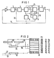
- Fig. 1, 1 denotes a connection to which an electrode leading to the heart can be connected.
- This electrode can be used to deliver impulses to the heart and to sense heart activity.
- Registered heartbeats are monitored via a Line 11 fed to an input amplifier 2. Its output signal reaches a detector 3 which only responds to cardiac signals.
- the signals passing through this detector reach a computer 5 via a line 31 and a gate 4.
- the gate 4 is opened via a clock generator 6 for a certain period of time, for example for two seconds . If the number of impulses reaching the computer reaches a predeterminable value or exceeds this value during this time, tachycardia is present and the computer generates an output signal which starts a further computer 7 via a line 51.
- a memory 8 with an internal computing unit is provided, which is described in more detail in FIG. 2.
- a specific value for a delay time is entered into the computer 7 from the memory 8 via a line 81.
- the computer receives 6 clock pulses with a frequency of, for example, one kHz from the clock generator.
- the output signal of the computer 7 is given via a line 71 to an output circuit 9 which, driven by this signal, emits a predetermined number of stimulation pulses via the line 91 to the connection 1.
- the output signal of the computer 7 is still given via a line 75 to the computer -5 and is used there as a reset signal.
- the output of the computer 7 is connected to the memory 8 via a line 78 and thereby controls a change in the delay time value given by the memory to the computer 7.
- the memory 8 is still subjected to the high-frequency clock signal.
- the output signal of the detector 3 is also given to the memory 8 via a line 32.
- the output 8 of the computer 5, ie practically the tachycardia detector, is given to the memory 8 as a further control signal via a line 52.
- a tachycardia is then assumed in section B.
- the computer 5 thus outputs an output signal to the computer 7 and starts it.
- This calculates, for example, from the delay time value d 1 taken from the memory 8 with the clock frequency backwards to zero and then emits an output signal which drives the output circuit 9 to generate a stimulation pulse.
- the delay time is shown as a rectangular pulse.
- a first stimulation pulse is delivered, which is shown in the middle part of FIG. 4 as a negative pulse. In the present example, this stimulation pulse is not at the correct time interval from the previous heartbeat to end the tachycardia.
- the computer 5 therefore starts the delayed generation of a stimulation pulse again after the predetermined number of tachycardia heartbeats has reappeared, four such heartbeats in the example in FIG. 4, but with an extended ver delay time d 2 . It is now assumed that the stimulation pulse delivered after this delay time ends the tachycardia. In section C of FIG. 4, the heart has returned to its normal heart rhythm.
- the computer 5 is simultaneously reset to its starting point and a signal is still output to the memory 8, as a result of which a different delay time value is input into the computer 7 . If the tachycardia is ended after this delay time, i.e. If no output signal occurs at the computer 5 at the end of a predeterminable time, the memory 8 is actuated via line 52 practically in the opposite direction, so that the computer 7 receives the old delay time value again. It is practically achieved that the arrangement "remembers" the correct delay time value for ending a tachycardia. When tachycardia occurs again, the first stimulation pulse delivered is delivered to the heart with the same time delay.
- FIG. 2 shows a possible embodiment of the memory 8 in a somewhat more detailed representation.
- An essential component of this memory is a register 8D with eight register locations in the present example.
- the smallest possible time delay is permanently entered in the top memory location. This time delay practically corresponds to the refractory period or is only slightly longer than this.
- the largest possible time delay which corresponds to the distance between two tachycardia heart signals, is entered in the lowest register position.
- This time for example determined in a computer 82, to which 61 clock pulses from the clock generator 6 and 32 heart signals are fed via a line.
- the resulting cardiac signals between two number of clock pulses is an M ass for the measured time period.
- the smallest value for the delay time is entered in a register 83, the largest first in a register 84.
- Half of the sum is formed from these two values in a stage 85 and is transferred via a line 86 to the next register location of the register 81.
- This value is then read into register 84 as a new value, after which the entire process is repeated until all of the locations in register 81 are occupied.
- the interval between two tachycardia heartbeats is 400 milliseconds and that the refractory time of the heart and, equated with this, the shortest delay time is 200 milliseconds. This results in the delay times specified next to the register positions.
- the third column next to register 81 shows the order of the different delay times that occur in such a case.
- FIG. 3 Another exemplary embodiment is shown in a block diagram in the following FIG. 3.
- the connection for the electrode leading to the heart is designated 1.
- the signals go via a line 11 to a stage 10, which contains both amplifier and detector.
- the signals are sent to a microprocessor, which determines and specifies the different time determinations as well as arithmetic operations and delay times.
- the output of this microprocessor 100 in turn controls an output circuit 9 for generating the stimulation pulses.
- microprocessor 100 can be programmed via a stage 200 with a receiving device 201.
- a similar programming device can also be provided for the arrangement according to FIG. 1.
- Both of the embodiments given by way of example can be part of an implanted pacemaker, which can also deliver stimulation pulses to the heart in the event of further cardiac arrhythmias.
Landscapes
- Health & Medical Sciences (AREA)
- Cardiology (AREA)
- Life Sciences & Earth Sciences (AREA)
- Animal Behavior & Ethology (AREA)
- General Health & Medical Sciences (AREA)
- Veterinary Medicine (AREA)
- Engineering & Computer Science (AREA)
- Biomedical Technology (AREA)
- Heart & Thoracic Surgery (AREA)
- Public Health (AREA)
- Molecular Biology (AREA)
- Surgery (AREA)
- Physics & Mathematics (AREA)
- Biophysics (AREA)
- Medical Informatics (AREA)
- Pathology (AREA)
- Nuclear Medicine, Radiotherapy & Molecular Imaging (AREA)
- Radiology & Medical Imaging (AREA)
- Electrotherapy Devices (AREA)
Applications Claiming Priority (2)
| Application Number | Priority Date | Filing Date | Title |
|---|---|---|---|
| SE8107269A SE8107269L (sv) | 1981-12-04 | 1981-12-04 | Anordning for att avsluta en takykardi |
| SE8107269 | 1981-12-04 |
Publications (2)
| Publication Number | Publication Date |
|---|---|
| EP0081209A1 true EP0081209A1 (fr) | 1983-06-15 |
| EP0081209B1 EP0081209B1 (fr) | 1986-09-24 |
Family
ID=20345204
Family Applications (1)
| Application Number | Title | Priority Date | Filing Date |
|---|---|---|---|
| EP82111174A Expired EP0081209B1 (fr) | 1981-12-04 | 1982-12-02 | Dispositif pour arrêter une tachycardie |
Country Status (5)
| Country | Link |
|---|---|
| US (1) | US4574437A (fr) |
| EP (1) | EP0081209B1 (fr) |
| JP (1) | JPS58103470A (fr) |
| DE (1) | DE3273490D1 (fr) |
| SE (1) | SE8107269L (fr) |
Cited By (10)
| Publication number | Priority date | Publication date | Assignee | Title |
|---|---|---|---|---|
| EP0161140A1 (fr) * | 1984-03-28 | 1985-11-13 | Medtronic, Inc. | Stimulateur actionnable par échantillonnage du rythme cardiaque et procédé pour le traitement de la tachycardie |
| US4554921A (en) * | 1983-02-11 | 1985-11-26 | Vitafin N.V. | Dual chamber pacemaker with automatic high rate limit mode determination |
| US4572192A (en) * | 1983-09-21 | 1986-02-25 | Board Of Regents For The University Of Oklahoma | System for prevention of paroxysmal supraventricular tachycardia |
| US4587970A (en) * | 1985-01-22 | 1986-05-13 | Telectronics N.V. | Tachycardia reversion pacer |
| EP0218789A1 (fr) * | 1985-10-04 | 1987-04-22 | Siemens Aktiengesellschaft | Stimulateur cardiaque commandé à partir de l'oreillette |
| EP0221235A1 (fr) * | 1985-10-04 | 1987-05-13 | Pacesetter AB | Stimulateur cardiaque commandé à partir de l'oreillette |
| US4712558A (en) * | 1984-03-13 | 1987-12-15 | Bio Medical Research Ltd. | Electrical stimulation of muscle |
| EP0363015A1 (fr) * | 1988-09-07 | 1990-04-11 | Medtronic, Inc. | Stimulateur cardiaque à stabilisation du rythme |
| EP0450943A2 (fr) * | 1990-04-03 | 1991-10-09 | Telectronics N.V. | Appareil et méthode de stimulation pour antitachycardies dans un système de commande d'arythmies |
| EP0450450A2 (fr) * | 1990-04-03 | 1991-10-09 | Pacesetter AB | Stimulateur cardiaque pour stopper les arrythmies |
Families Citing this family (11)
| Publication number | Priority date | Publication date | Assignee | Title |
|---|---|---|---|---|
| DE3535517A1 (de) * | 1985-10-04 | 1987-04-09 | Siemens Ag | Vorhofgesteuerter herzschrittmacher |
| US4830006B1 (en) * | 1986-06-17 | 1997-10-28 | Intermedics Inc | Implantable cardiac stimulator for detection and treatment of ventricular arrhythmias |
| US4940054A (en) * | 1988-04-29 | 1990-07-10 | Telectronics N.V. | Apparatus and method for controlling multiple sensitivities in arrhythmia control system including post therapy packing delay |
| SE9100229D0 (sv) * | 1991-01-25 | 1991-01-25 | Siemens Elema Ab | Implanterbar medicinsk apparat foer stimulering av ett hjaerta |
| US5354316A (en) * | 1993-01-29 | 1994-10-11 | Medtronic, Inc. | Method and apparatus for detection and treatment of tachycardia and fibrillation |
| US5342402A (en) * | 1993-01-29 | 1994-08-30 | Medtronic, Inc. | Method and apparatus for detection and treatment of tachycardia and fibrillation |
| US5489293A (en) * | 1993-08-31 | 1996-02-06 | Ventritex, Inc. | Method and apparatus for treating cardiac tachyarrhythmia |
| US5431689A (en) * | 1993-09-23 | 1995-07-11 | Pacesetter, Inc. | Implantable stimulation system and method for terminating cardiac arrhythmias |
| US5882352A (en) * | 1995-05-25 | 1999-03-16 | Pacesetter, Inc. | Automatic adjustment of detection rate threshold in an implantable antitachycardia therapy device |
| US6668195B2 (en) | 2001-10-30 | 2003-12-23 | Medtronic, Inc. | Methods and apparatus for reducing the likelihood of atrial fibrillation |
| US7162300B2 (en) * | 2003-01-13 | 2007-01-09 | Medtronic, Inc. | Synchronized atrial anti-tachy pacing system and method |
Citations (8)
| Publication number | Priority date | Publication date | Assignee | Title |
|---|---|---|---|---|
| DE2528817A1 (de) * | 1974-07-10 | 1976-01-29 | Medtronic Inc | Vorrichtung zum verhindern von arrhythmien |
| US3942534A (en) * | 1973-11-21 | 1976-03-09 | Kenneth Roy Allen | Device for terminating tachycardia |
| DE2838360A1 (de) * | 1977-09-08 | 1979-03-22 | Avl Ag | Verfahren und einrichtung zum ermitteln von systolischen zeitintervallen |
| DE2845323A1 (de) * | 1977-10-26 | 1979-05-03 | Cordis Corp | Verfahren und herzschrittmacher zur erzeugung von herz-stimulationsimpulsen |
| EP0023134A1 (fr) * | 1979-07-19 | 1981-01-28 | Medtronic, Inc. | Dispositif correcteur du rythme cardiaque implantable |
| US4280502A (en) * | 1979-08-08 | 1981-07-28 | Intermedics, Inc. | Tachycardia arrester |
| US4285041A (en) * | 1979-06-22 | 1981-08-18 | Smith Kent G | Digital pacing timer |
| GB2083363A (en) * | 1980-08-05 | 1982-03-24 | Mirowski Mieczyslaw | Automatic defibrillator |
Family Cites Families (6)
| Publication number | Priority date | Publication date | Assignee | Title |
|---|---|---|---|---|
| FR2248020B1 (fr) * | 1973-10-18 | 1977-05-27 | Pequignot Michel | |
| US4181133A (en) * | 1978-05-22 | 1980-01-01 | Arco Medical Products Company | Programmable tachycardia pacer |
| US4228803A (en) * | 1978-06-23 | 1980-10-21 | Credit Du Nord International N.V. | Physiologically adaptive cardiac pacemaker |
| ATE3946T1 (de) * | 1978-08-22 | 1983-07-15 | Siemens Aktiengesellschaft | Vorrichtung zum untersuchen oder regeln einer erhoehten herzfrequenz. |
| DE3110014A1 (de) * | 1980-05-19 | 1982-03-25 | Telectronics Pty. Ltd., Lane Cove, New South Wales | Aeusserlich rueckstellbarer tachykardie-regelschrittmacher |
| US4406287A (en) * | 1981-07-17 | 1983-09-27 | Telectronics Pty. Ltd. | Variable length scanning burst tachycardia control pacer |
-
1981
- 1981-12-04 SE SE8107269A patent/SE8107269L/ not_active Application Discontinuation
-
1982
- 1982-12-02 DE DE8282111174T patent/DE3273490D1/de not_active Expired
- 1982-12-02 EP EP82111174A patent/EP0081209B1/fr not_active Expired
- 1982-12-03 JP JP57212600A patent/JPS58103470A/ja active Granted
-
1985
- 1985-05-23 US US06/736,990 patent/US4574437A/en not_active Expired - Lifetime
Patent Citations (8)
| Publication number | Priority date | Publication date | Assignee | Title |
|---|---|---|---|---|
| US3942534A (en) * | 1973-11-21 | 1976-03-09 | Kenneth Roy Allen | Device for terminating tachycardia |
| DE2528817A1 (de) * | 1974-07-10 | 1976-01-29 | Medtronic Inc | Vorrichtung zum verhindern von arrhythmien |
| DE2838360A1 (de) * | 1977-09-08 | 1979-03-22 | Avl Ag | Verfahren und einrichtung zum ermitteln von systolischen zeitintervallen |
| DE2845323A1 (de) * | 1977-10-26 | 1979-05-03 | Cordis Corp | Verfahren und herzschrittmacher zur erzeugung von herz-stimulationsimpulsen |
| US4285041A (en) * | 1979-06-22 | 1981-08-18 | Smith Kent G | Digital pacing timer |
| EP0023134A1 (fr) * | 1979-07-19 | 1981-01-28 | Medtronic, Inc. | Dispositif correcteur du rythme cardiaque implantable |
| US4280502A (en) * | 1979-08-08 | 1981-07-28 | Intermedics, Inc. | Tachycardia arrester |
| GB2083363A (en) * | 1980-08-05 | 1982-03-24 | Mirowski Mieczyslaw | Automatic defibrillator |
Cited By (14)
| Publication number | Priority date | Publication date | Assignee | Title |
|---|---|---|---|---|
| US4554921A (en) * | 1983-02-11 | 1985-11-26 | Vitafin N.V. | Dual chamber pacemaker with automatic high rate limit mode determination |
| US4572192A (en) * | 1983-09-21 | 1986-02-25 | Board Of Regents For The University Of Oklahoma | System for prevention of paroxysmal supraventricular tachycardia |
| US4712558A (en) * | 1984-03-13 | 1987-12-15 | Bio Medical Research Ltd. | Electrical stimulation of muscle |
| EP0161140A1 (fr) * | 1984-03-28 | 1985-11-13 | Medtronic, Inc. | Stimulateur actionnable par échantillonnage du rythme cardiaque et procédé pour le traitement de la tachycardie |
| US4587970A (en) * | 1985-01-22 | 1986-05-13 | Telectronics N.V. | Tachycardia reversion pacer |
| EP0189320A2 (fr) * | 1985-01-22 | 1986-07-30 | Telectronics N.V. | Entraîneur cardiaque pour arrêter une tachycardie |
| EP0189320A3 (en) * | 1985-01-22 | 1989-12-06 | Telectronics N.V. | Tachycardia reversion pacer |
| EP0221235A1 (fr) * | 1985-10-04 | 1987-05-13 | Pacesetter AB | Stimulateur cardiaque commandé à partir de l'oreillette |
| EP0218789A1 (fr) * | 1985-10-04 | 1987-04-22 | Siemens Aktiengesellschaft | Stimulateur cardiaque commandé à partir de l'oreillette |
| EP0363015A1 (fr) * | 1988-09-07 | 1990-04-11 | Medtronic, Inc. | Stimulateur cardiaque à stabilisation du rythme |
| EP0450943A2 (fr) * | 1990-04-03 | 1991-10-09 | Telectronics N.V. | Appareil et méthode de stimulation pour antitachycardies dans un système de commande d'arythmies |
| EP0450450A2 (fr) * | 1990-04-03 | 1991-10-09 | Pacesetter AB | Stimulateur cardiaque pour stopper les arrythmies |
| EP0450450A3 (en) * | 1990-04-03 | 1992-02-12 | Siemens Elema Ab | Pacemaker for termination of a cardiac arrhythmia |
| EP0450943A3 (en) * | 1990-04-03 | 1992-12-16 | Telectronics N.V. | Apparatus and method for antitachycardia pacing in arrhythmia control systems |
Also Published As
| Publication number | Publication date |
|---|---|
| SE8107269L (sv) | 1983-06-05 |
| JPS6150465B2 (fr) | 1986-11-04 |
| JPS58103470A (ja) | 1983-06-20 |
| US4574437A (en) | 1986-03-11 |
| DE3273490D1 (en) | 1986-10-30 |
| EP0081209B1 (fr) | 1986-09-24 |
Similar Documents
| Publication | Publication Date | Title |
|---|---|---|
| EP0081209B1 (fr) | Dispositif pour arrêter une tachycardie | |
| EP0108360B2 (fr) | Entraîneur cardiaque pour arrêter une tachycardie | |
| DE69319641T2 (de) | Detektion von Tachykardie und Herzflimmern | |
| DE69632853T2 (de) | Herzschrittmacher mit automatischer Funktion für die Austastzeit | |
| DE3732699C2 (de) | Implantierbarer Herzschrittmacher | |
| DE69117410T2 (de) | System zur Erkennung und Beendung von durch einen Herzschrittmacher induzierten Tachykardien | |
| DE2823804C2 (de) | Programmierbarer, einpflanzbarer Herzschrittmacher | |
| DE69625925T2 (de) | Vorrichtung zur hämodynamischen stimulation bei einer ventrikulären tachykardie | |
| DE69233272T2 (de) | Verfahren und gerät zur energieregelung beim stimulieren in einem herzschrittmacher | |
| DE69115973T3 (de) | Schrittmacher für Antitachykardien in einem Arrythmiesteuersystem | |
| DE69430731T2 (de) | Implantierbarer herzschrittmacher zur beendigung von herzarrhythmie | |
| DE3878265T2 (de) | Ekg-vorrichtung. | |
| DE2449696A1 (de) | Verfahren und vorrichtung zur elektrischen erregung eines herzens | |
| DE69526408T2 (de) | Zweikammer-Herzschrittmachersystem mit verbesserter Reaktion auf retrograde Leitung | |
| DE3117075C2 (de) | Vorhofsynchroner Herzschrittmacher | |
| DE2455237A1 (de) | Vorrichtung zum beenden von tachycardie | |
| DE3110014A1 (de) | Aeusserlich rueckstellbarer tachykardie-regelschrittmacher | |
| DE2314315C2 (de) | Bedarfsgesteuerter atrialer und ventrikularer Herzschrittmacher | |
| DE69824119T2 (de) | Implantierbare aktive medizinische Einrichtung, insbesondere Herzstimulator, gesteuert von wenigstens einem physiologischen Parameter | |
| DE2458475A1 (de) | Vorrichtung zur herzueberwachung | |
| EP0238966B1 (fr) | Stimulateur cardiaque commandé par l'action atriale | |
| DE60016600T2 (de) | Herzschrittmacher | |
| DE3311509C2 (de) | Vorrichtung zum Erkennen eines interessierenden physiologischen Vorgangs | |
| EP1013306B1 (fr) | Stimulateur cardiaque double chambre | |
| DE69529326T2 (de) | Zweikammer-Herzschrittmacher-System mit verbesserter Umschaltung zwischen dem synchronen und dem asynchronen Modus |
Legal Events
| Date | Code | Title | Description |
|---|---|---|---|
| PUAI | Public reference made under article 153(3) epc to a published international application that has entered the european phase |
Free format text: ORIGINAL CODE: 0009012 |
|
| AK | Designated contracting states |
Designated state(s): DE FR GB NL SE |
|
| 17P | Request for examination filed |
Effective date: 19831128 |
|
| GRAA | (expected) grant |
Free format text: ORIGINAL CODE: 0009210 |
|
| AK | Designated contracting states |
Kind code of ref document: B1 Designated state(s): DE FR GB NL SE |
|
| REF | Corresponds to: |
Ref document number: 3273490 Country of ref document: DE Date of ref document: 19861030 |
|
| ET | Fr: translation filed | ||
| PLBE | No opposition filed within time limit |
Free format text: ORIGINAL CODE: 0009261 |
|
| STAA | Information on the status of an ep patent application or granted ep patent |
Free format text: STATUS: NO OPPOSITION FILED WITHIN TIME LIMIT |
|
| 26N | No opposition filed | ||
| PGFP | Annual fee paid to national office [announced via postgrant information from national office to epo] |
Ref country code: SE Payment date: 19901212 Year of fee payment: 9 |
|
| PG25 | Lapsed in a contracting state [announced via postgrant information from national office to epo] |
Ref country code: SE Effective date: 19911203 |
|
| EUG | Se: european patent has lapsed |
Ref document number: 82111174.7 Effective date: 19920704 |
|
| REG | Reference to a national code |
Ref country code: GB Ref legal event code: 732E |
|
| REG | Reference to a national code |
Ref country code: FR Ref legal event code: TP |
|
| NLS | Nl: assignments of ep-patents |
Owner name: PACESETTER AB |
|
| PGFP | Annual fee paid to national office [announced via postgrant information from national office to epo] |
Ref country code: GB Payment date: 19971114 Year of fee payment: 16 Ref country code: FR Payment date: 19971114 Year of fee payment: 16 |
|
| PGFP | Annual fee paid to national office [announced via postgrant information from national office to epo] |
Ref country code: NL Payment date: 19971130 Year of fee payment: 16 |
|
| PGFP | Annual fee paid to national office [announced via postgrant information from national office to epo] |
Ref country code: DE Payment date: 19971210 Year of fee payment: 16 |
|
| PG25 | Lapsed in a contracting state [announced via postgrant information from national office to epo] |
Ref country code: GB Free format text: LAPSE BECAUSE OF NON-PAYMENT OF DUE FEES Effective date: 19981202 |
|
| PG25 | Lapsed in a contracting state [announced via postgrant information from national office to epo] |
Ref country code: NL Free format text: LAPSE BECAUSE OF NON-PAYMENT OF DUE FEES Effective date: 19990701 |
|
| GBPC | Gb: european patent ceased through non-payment of renewal fee |
Effective date: 19981202 |
|
| PG25 | Lapsed in a contracting state [announced via postgrant information from national office to epo] |
Ref country code: FR Free format text: LAPSE BECAUSE OF NON-PAYMENT OF DUE FEES Effective date: 19990831 |
|
| NLV4 | Nl: lapsed or anulled due to non-payment of the annual fee |
Effective date: 19990701 |
|
| REG | Reference to a national code |
Ref country code: FR Ref legal event code: ST |
|
| PG25 | Lapsed in a contracting state [announced via postgrant information from national office to epo] |
Ref country code: DE Free format text: LAPSE BECAUSE OF NON-PAYMENT OF DUE FEES Effective date: 19991001 |