EP0081055B1 - Record carrier with a multi-coloured micro-image, especially in the form of a micro map, and process for the manufacture of this record carrier - Google Patents
Record carrier with a multi-coloured micro-image, especially in the form of a micro map, and process for the manufacture of this record carrier Download PDFInfo
- Publication number
- EP0081055B1 EP0081055B1 EP82109176A EP82109176A EP0081055B1 EP 0081055 B1 EP0081055 B1 EP 0081055B1 EP 82109176 A EP82109176 A EP 82109176A EP 82109176 A EP82109176 A EP 82109176A EP 0081055 B1 EP0081055 B1 EP 0081055B1
- Authority
- EP
- European Patent Office
- Prior art keywords
- layer
- layers
- recording medium
- absorption
- layered
- Prior art date
- Legal status (The legal status is an assumption and is not a legal conclusion. Google has not performed a legal analysis and makes no representation as to the accuracy of the status listed.)
- Expired
Links
Images


Classifications
-
- G—PHYSICS
- G03—PHOTOGRAPHY; CINEMATOGRAPHY; ANALOGOUS TECHNIQUES USING WAVES OTHER THAN OPTICAL WAVES; ELECTROGRAPHY; HOLOGRAPHY
- G03F—PHOTOMECHANICAL PRODUCTION OF TEXTURED OR PATTERNED SURFACES, e.g. FOR PRINTING, FOR PROCESSING OF SEMICONDUCTOR DEVICES; MATERIALS THEREFOR; ORIGINALS THEREFOR; APPARATUS SPECIALLY ADAPTED THEREFOR
- G03F7/00—Photomechanical, e.g. photolithographic, production of textured or patterned surfaces, e.g. printing surfaces; Materials therefor, e.g. comprising photoresists; Apparatus specially adapted therefor
- G03F7/004—Photosensitive materials
- G03F7/09—Photosensitive materials characterised by structural details, e.g. supports, auxiliary layers
- G03F7/095—Photosensitive materials characterised by structural details, e.g. supports, auxiliary layers having more than one photosensitive layer
-
- G—PHYSICS
- G03—PHOTOGRAPHY; CINEMATOGRAPHY; ANALOGOUS TECHNIQUES USING WAVES OTHER THAN OPTICAL WAVES; ELECTROGRAPHY; HOLOGRAPHY
- G03C—PHOTOSENSITIVE MATERIALS FOR PHOTOGRAPHIC PURPOSES; PHOTOGRAPHIC PROCESSES, e.g. CINE, X-RAY, COLOUR, STEREO-PHOTOGRAPHIC PROCESSES; AUXILIARY PROCESSES IN PHOTOGRAPHY
- G03C7/00—Multicolour photographic processes or agents therefor; Regeneration of such processing agents; Photosensitive materials for multicolour processes
-
- Y—GENERAL TAGGING OF NEW TECHNOLOGICAL DEVELOPMENTS; GENERAL TAGGING OF CROSS-SECTIONAL TECHNOLOGIES SPANNING OVER SEVERAL SECTIONS OF THE IPC; TECHNICAL SUBJECTS COVERED BY FORMER USPC CROSS-REFERENCE ART COLLECTIONS [XRACs] AND DIGESTS
- Y10—TECHNICAL SUBJECTS COVERED BY FORMER USPC
- Y10S—TECHNICAL SUBJECTS COVERED BY FORMER USPC CROSS-REFERENCE ART COLLECTIONS [XRACs] AND DIGESTS
- Y10S428/00—Stock material or miscellaneous articles
- Y10S428/913—Material designed to be responsive to temperature, light, moisture
-
- Y—GENERAL TAGGING OF NEW TECHNOLOGICAL DEVELOPMENTS; GENERAL TAGGING OF CROSS-SECTIONAL TECHNOLOGIES SPANNING OVER SEVERAL SECTIONS OF THE IPC; TECHNICAL SUBJECTS COVERED BY FORMER USPC CROSS-REFERENCE ART COLLECTIONS [XRACs] AND DIGESTS
- Y10—TECHNICAL SUBJECTS COVERED BY FORMER USPC
- Y10T—TECHNICAL SUBJECTS COVERED BY FORMER US CLASSIFICATION
- Y10T428/00—Stock material or miscellaneous articles
- Y10T428/24—Structurally defined web or sheet [e.g., overall dimension, etc.]
- Y10T428/24802—Discontinuous or differential coating, impregnation or bond [e.g., artwork, printing, retouched photograph, etc.]
- Y10T428/24917—Discontinuous or differential coating, impregnation or bond [e.g., artwork, printing, retouched photograph, etc.] including metal layer
Abstract
Description
Die Erfindung betrifft einen Aufzeichnungsträger mit einer mehrfarbigen Feinstruktur gemäss dem Oberbegriff des Anspruchs 1.The invention relates to a recording medium with a multi-colored fine structure.
In der US-A Nr. 3727233 ist eine Methode zur Aufzeichnung eines mehrfarbigen Bildes beschrieben, bei der auf einem Schichtträger aus Glas eine Metallschicht hoher Reflektivität und darauf eine organische Polymerschicht aufgebracht werden. Die Polymerschicht wird mittels ein abzubildendes Objekt durchdringender Elektronenstrahlen belichtet sowie anschliessend entwickelt und besitzt danach durch Polymerisation eine Struktur entsprechend der Bestrahlungsintensität der Elektronenstrahlen. Anschliessend wird auf die strukturierte organische Polymerschicht eine weitere Metallschicht hoher Reflektivität aufgebracht, so dass sich infolge Interferenz ein mehrfarbiges Bild bei natürlichem Licht ergibt. Als nachteilig erweist es sich, dass die über den gesamten Schichtträger mit gleicher Schichtdicke aufgebrachten Metallschichten keine unterschiedlichen Sättigungen der einzelnen Farbtöne des Bildes erlauben. Die strukturierte Interferenzschicht in Form der organischen Polymerschicht lässt wegen ihrer erheblichen Wärmeempfindlichkeiteine starke Rückvergrösserung des mehrfarbigen Bildes wegen der damit verbundenen hohen Beleuchtungsstärken nicht zu; durch die mangelnde Lichtechtheit und Schrumpfung der organischen Inteferenzschicht im Laufe der Zeit können zudem Farbveränderungen auftreten.US Pat. No. 3,727,233 describes a method for recording a multicolored image in which a metal layer of high reflectivity and an organic polymer layer are applied to a layer support made of glass. The polymer layer is exposed by means of electron beams penetrating an object to be imaged and then developed and then has a structure corresponding to the radiation intensity of the electron beams by means of polymerization. A further metal layer of high reflectivity is then applied to the structured organic polymer layer, so that a multicolored image results in natural light as a result of interference. It proves to be disadvantageous that the metal layers applied over the entire layer support with the same layer thickness do not allow different saturations of the individual color tones of the image. The structured interference layer in the form of the organic polymer layer, because of its considerable sensitivity to heat, does not allow the multicolored image to be greatly re-enlarged due to the associated high illuminance levels; Due to the lack of lightfastness and shrinkage of the organic interference layer over time, color changes can also occur.
Aus der DE-A Nr. 2658623 ist ein Aufzeichnungsträger mit einer Aufzeichnung hoher Informationsdichte, insbesondere mit einem mehrfarbigen Mikrobild bekannt, bei dem auf einem Schichtträger wenigstens zwei Interferenzfilterfür zwei unterschiedliche Farbtöne vorgesehen sind. Jedes lnterferenzfilter besteht aus einer unstrukturierten anorganischen absorptionsfreien Interferenzschicht, die sich mit gleicher Schichtdicke über den gesamten Schichtträger erstreckt und auf jeder Seite durch wenigstens eine die Struktur der Aufzeichnung bildende anorganische spiegelnde Schicht begrenzt ist. In einer weiteren Ausbildung ist die unstrukturierte Interferenzschicht auf jeder Seite durch wenigstens eine strukturierte hochbrechende absorptionsfreie Schicht begrenzt, wobei sich zwischen je zwei hochbrechenden Schichten eine unstrukturierte niedrigbrechende absorptionsfreie Schicht befindet. Da sich zwischen den die Struktur bildenden spiegelnden Schichten die unstrukturierte Interferenzschicht bzw. zwischen den die Struktur bildenden hochbrechenden Schichten die unstrukturierte Interferenzschicht und die unstrukturierten niedrigbrechenden Schichten befinden, die sich ebenfalls mit gleicher Schichtdicke über den gesamten Schichtträger erstrecken, sind für jeden Farbton eine Reihe von Strukturierungsschritten erforderlich, bei denen aber die Mehrfachjustierung der betreffenden Belichtungsmaske grösste Justiergenauigkeit erfordert und ausserdem zeitaufwendig ist.DE-A No. 2658623 discloses a recording medium with a recording of high information density, in particular with a multicolored microimage, in which at least two interference filters for two different color tones are provided on a layer carrier. Each interference filter consists of an unstructured inorganic absorption-free interference layer which extends with the same layer thickness over the entire layer support and is delimited on each side by at least one inorganic reflective layer which forms the structure of the recording. In a further embodiment, the unstructured interference layer is delimited on each side by at least one structured highly refractive absorption-free layer, an unstructured low refractive absorption-free layer being located between every two high refractive layers. Since the unstructured interference layer is between the reflecting layers forming the structure and the unstructured interference layer and the unstructured low-refractive layers between the high-refractive layers forming the structure, which also extend with the same layer thickness over the entire layer support, there are a number of for each color Structuring steps are required, but in which the multiple adjustment of the exposure mask in question requires the greatest adjustment accuracy and is also time-consuming.
Der Erfindung liegt die Aufgabe zugrunde, bei einem Aufzeichnungsträger der oben genannten Gattung die Anzahl der Verfahrensschritte zu reduzieren, Justierungsprobleme zu vermeiden und die optische Güte der Feinstruktur zu verbessern.The invention is based on the object of reducing the number of method steps in a recording medium of the type mentioned above, avoiding adjustment problems and improving the optical quality of the fine structure.
Diese Aufgabe wird erfindungsgemäss im wesentlichen durch die kennzeichnenden Merkmale des Anspruchs 1 gelöst.According to the invention, this object is essentially achieved by the characterizing features of
Die mit der Erfindung erzielten Vorteile bestehen insbesondere darin, dass bei der Herstellung eines solchen Aufzeichnungsträgers der Zeit- und Kostenfaktor sowie die Ausschussrate erheblich gesenkt und eine bessere Farbtonreinheit und Farbtonsättigung erzielt werden.The advantages achieved by the invention consist in particular in the fact that the time and cost factor and the reject rate are considerably reduced and a better color purity and color saturation are achieved in the production of such a recording medium.
Vorteilhafte Ausgestaltungen sowie Verfahren zur Herstellung derartiger Aufzeichnungsträger entnimmt man den Unteransprüchen.Advantageous refinements and methods for producing such recording media can be found in the subclaims.
Ausführungsbeispiele der Erfindung sind in der Zeichnung dargestellt und werden im folgenden näher erläutert. Es zeigen:
- Fig. 1 bis 1 c Aufzeichnungsträger mit metalldieleketrischen Interferenzfiltern,
- Fig. 2a, 2b Aufzeichnungsträger mit reindielektrischen Interferenzfiltern,
- Fig. 3a, 3b Aufzeichnungsträger mit Halbfiltern,
- Fig.4a bis 4d Aufzeichnungsträger mit induzierten Transmissionsfiltern,
- Fig. 5a, 5b Aufzeichnungsträger mit Kantenfiltern (Reflektoren) und
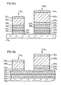
- Fig. 6a, 6b Aufzeichnungsträger mit Kantenfiltern und metalldielektrischen Filtern.
- 1 to 1 c recording medium with metal dielectric interference filters,
- 2a, 2b recording media with pure dielectric interference filters,
- 3a, 3b recording medium with half filters,
- 4a to 4d recording media with induced transmission filters,
- 5a, 5b recording media with edge filters (reflectors) and
- 6a, 6b recording media with edge filters and metal dielectric filters.
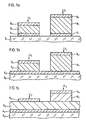
In Fig. 1 bis 1 sind Aufzeichnungsträger mit metalldielektrischen Interferenzfiltern in Form von Schichtpaketen 11,12,13 für einen ersten Farbton und von Schichtpaketen 21, 22, 23 für einen zweiten Farbton dargestellt.1 to 1 show recording media with metal-dielectric interference filters in the form of
Zur Erzeugung des ersten Farbtons wird gemäss Fig. 1 a auf einem Schichtträger 31 in nicht gezeigter Weise ganzflächig eine erste Photolackschicht aufgebracht und mittels einer ersten Belichtungsmaske belichtet. Nach dem Entwickeln der ersten Photolackschicht werden auf dem Schichtträger 31 ganzflächig eine Metallschicht 41, eine anorganische absorptionsfreie Interferenzschicht 51 gemäss dem ersten Farbton und eine Metallschicht 6, aufgebracht. Die verbliebene erste Photolackschicht mitsamt den darüber befindlichen Schichten 41 -61 wird sodann entfernt, so dass das Schichtpaket 11 auf dem Schichtträger 3, verbleibt. Zur Erzeugung des zweiten Farbtons wird auf dem Schichtträger 3, ganzflächig eine zweite Photolackschicht aufgebracht und mittels einer zweiten Belichtungsmaske belichtet. Nach dem Entwickeln der zweiten Photolackschicht werden auf dem Schichtträger 3, ganzflächig eine Metallschicht 71, eine anorganische absorptionsfreie Interferenzschicht 8, gemäss dem zweiten Farbton und eine Metallschicht 91 aufgebracht. Die verbliebene zweite Photolackschicht mitsamt den darüber befindlichen Schichten 71 -91 wird sodann entfernt, so dass neben dem Schichtpaket 1, das Schichtpaket 21 auf dem Schichtträger 31 verbleibt.For generating the first hue A is shown in FIG. 1 blanket deposited on a substrate 3 1 in a manner not shown, a first layer of photoresist and exposed using a first exposure mask. After the development of the first photoresist layer, a metal layer 4 1 , an inorganic absorption-
In einer anderen Ausbildung dieses Aufzeichnungsträgers werden nach Fig. 1 b auf einem Schichtträger 32 ganzflächig eine Metallschicht 42 und darüber zur Erzeugung des ersten Farbtons eine erste Photolackschicht aufgebracht. Nach dem Belichten der ersten Photolackschicht mittels der ersten Belichtungsmaske und dem Entwickeln der ersten Photolackschicht werden auf der Metallschicht 42 ganzflächig eine anorganische absorptionsfreie Interferenzschicht 52 gemäss dem ersten Farbton und eine Metallschicht 62 aufgebracht. Die verbliebene erste Photolackschicht mitsamt den darüber befindlichen Schichten 52, 62 wird sodann entfernt, so dass das Schichtpaket 12 auf dem Schichtträger 32 verbleibt. Zur Erzeugung der zweiten Farbtons wird auf der Metallschicht 42 ganzflächig eine zweite Photolackschicht aufgebracht und mittels der zweiten Belichtungsmaske belichet. Nach dem Entwickeln der zweiten Photolackschicht werden auf der Metallschicht 42 ganzflächig eine anorganische absorptionsfreie Interferenzschicht 82 gemäss dem zweiten Farbton und eine Metallschicht 92 aufgebracht. Die verbliebene zweite Photolackschicht mitsamt den darüber befindlichen Schichten 82, 92 wird sodann entfernt, so dass neben dem Schichtpaket 12 das Schichtpaket 22 auf dem Schichtträger 32 verbleibt.In another embodiment of this record carrier according to Fig. 1 b on a Layer support 3 2 has a metal layer 4 2 over its entire surface and a first photoresist layer is applied over it to produce the first color. After the exposure of the first photoresist layer by means of the first exposure mask and the development of the first photoresist layer, an inorganic absorption-
In einer weiteren Ausbildung dieses Aufzeichnungsträgers werden nach Fig. 1 C auf einem Schichtträger 33 ganzflächig eine Metallschicht 43 und darüber zur Erzeugung des ersten Farbtons eine anorganische absorptionsfreie Interferenzschicht 53 aufgebracht, die nachfolgend ganzflächig mit einer ersten Photolackschicht bedeckt wird. Nach dem Belichten der ersten Photolackschicht mittels der ersten Belichtungsmaske und dem Entwickeln der ersten Photolackschicht wird auf dem Schichtträger 33 ganzflächig eine Metallschicht 63 aufgebracht. Die verbliebene erste Photolackschicht mitsamt der darüber befindlichen Metallschicht 63 wird sodann entfernt, so dass das Schichtpaket 13 auf dem Schichtträger 33 verbleibt. Zur Erzeugung des zweiten Farbtons wird auf dem Schichtträger 33 ganzflächig eine zweite Photolackschicht aufgebracht und mittels der zweiten Belichtungsmaske belichtet. Nach den Entwickeln der zweiten Photolackschicht werden auf dem Schichtträger 33 ganzflächig eine anorganische absorptionsfreie Interferenzschicht 83 und eine Metallschicht 93 aufgebracht. Die verbliebene zweite Photolackschicht mitsamt den darüber befindlichen Schichten 83, 93 wird sodann entfernt, so dass neben dem Schichtpaket 13 das Schichtpaket 23 auf dem Schichtträger 33 verbleibt.In a further embodiment of this recording medium, according to FIG. 1 C, a metal layer 4 3 is applied over the entire surface of a layer support 3 3 and an inorganic absorption-
Im Bereich des Schichtpakets 23 bilden die Interferenzschichten 53, 83 zusammen die Interferenzschicht für den zweiten Farbton. Bei dem Schichtpaket 1 1, bilden die Schichten 41, 51, 61, bei dem Schichtpaket 12 die Schichten 52, 62, bei dem Schichtpaket 13 die Schicht 63, bei dem Schichtpaket 21 die Schichten 71, 81, 91, bei dem Schichtpaket 22die Schichten 82, 92 und bei dem Schichtpaket 23 die Schichten 83, 93 jeweils den strukturbildenden Teil. Die Metallschichten 4, 6, 7, 9 sind teildurchlässige Schichten.In the area of the layer package 2 3 , the
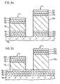
In Fig. 2a, 2b sind Aufzeichnungsträger mit reindielektrischen Interferenzfiltern in Form von Schichtpaketen 111, 112 für einen ersten Farbton und von Schichtpaketen 121, 122 für einen zweiten Farbton dargestellt.2a, 2b show recording media with pure dielectric interference filters in the form of
Zur Erzeugung des ersten Farbtons wird gemäss Fig. 2a auf einem Schichtträger 131 in nicht gezeigter Weise ganzflächig eine erste Photolackschicht aufgebracht und mittels einer ersten Belichtungsmaske belichtet. Nach dem Entwickeln der ersten Photolackschicht werden auf dem Schichtträger 131 ganzflächig eine hochbrechende absorptionsfreie Schicht 141, eine niedrigbrechende absorptionsfreie Schicht 151, eine hochbrechende absorptionsfreie Schicht 161, eine anorganische absorptionsfreie Interferenzschicht 171 gemäss dem ersten Farbton, eine hochbrechende absorptionsfreie Schicht 181, eine niedrigbrechende absorptionsfreie Schicht 191 und eine hochbrechende absorptionsfreie Schicht 201 aufgebracht. Die verbliebene erste Photolackschicht mitsamt den darüber befindlichen Schichten 141 - 201 wird sodann entfernt, so dass das Schichtpaket 111 auf dem Schichtträger 131 verbleibt. Zur Erzeugung des zweiten Farbtons wird auf dem Schichtträger 131 ganzflächig eine zweite Photolackschicht aufgebracht und mittels einer zweiten Belichtungsmaske belichtet. Nach dem Entwikkein der zweiten Photolackschicht werden auf dem Schichtträger 131 ganzflächig eine hochbrechende absorptionsfreie Schicht 211, eine niedrigbrechende absorptionsfreie Schicht 221, eine hochbrechende absorptionsfreie Schicht 231, eine anorganische absorptionsfreie Interferenzschicht 241 gemäss dem zweiten Farbton, eine hochbrechende absorptionsfreie Schicht 251, eine niedrigbrechende absorptionsfreie Schicht 261 und eine hochbrechende absorptionsfreie Schicht 271 aufgebracht. Die verbliebene zweite Photolackschicht mitsamt den darüber befindlichen Schichten 211 -271 wird sodann entfernt, so dass neben dem Schichtpacket 111 das Schichtpaket 121 auf dem Schichtträger 131 verbleibt.To produce the first color tone, a first photoresist layer is applied over the entire surface of a
In einer anderen Ausbildung dieses Aufzeichnungsträgers werden nach Fig. 2b auf einem Schichtträger 132 ganzflächig eine hochbrechende absorptionsfreie Schicht 142, eine niedrigbrechende absorptionsfreie Schicht 152 und eine hochbrechende absorptionsfreie Schicht 162 sowie zur Erzeugung des ersten Farbtons darüber eine erste Photolackschicht aufgebracht. Nach dem Belichten der ersten Photolackschicht mittels der ersten Belichtungsmaske und dem Entwickeln der ersten Photolackschicht werden auf der Schicht 162 ganzflächig eine anorganische absorptionsfreie Interferenzschicht 172 gemäss dem ersten Farbton, eine hochbrechende absorptionsfreie Schicht 182, eine niedrigbrechende absorptionsfreie Schicht 192 und eine hochbrechende absorptionsfreie Schicht 202 aufgebracht. Die verbliebene erste Photolackschicht mitsamt den darüber befindlichen Schichten 172-202 wird sodann entfernt, so dass das Schichtpaket 112 auf dem Schichtträger 132 verbleibt. Zur Erzeugung des zweiten Farbtons wird auf der Schicht 162 ganzflächig eine zweite Photolackschicht aufgebracht und mittels der zweiten Belichtungsmaske belichtet. Nach dem Entwickeln der zweiten Photolackschicht werden auf der Schicht 162 ganzflächig eine Interferenzschicht 242 gemäss dem zweiten Farbton, eine hochbrechende absorptionsfreie Schicht 252, eine niedrigbrechende absorptionsfreie Schicht 262 und eine hochbrechende absorptionsfreie Schicht 272 aufgebracht. Die verbliebene zweite Photolackschicht mitsamt den darüber bedindlichen Schichten 242- 272 wird sodann entfernt, so dass neben dem Schichtpaket 112 das Schichtpaket 122 auf dem Schichtträger 132 verbleibt.In another embodiment of this record carrier, a high-refractive absorption-free layer 14 2 , a low-refractive absorption-
Bei dem Schichtpaket 111 bilden die Schichten 141 -201, bei dem Schichtpaket 112 die Schichten 172-202, bei dem Schichtpaket 121 die Schichten 211-271 und bei dem Schichtpaket 122 die Schichten 242-272 jeweils den strukturbildenden Teil.In the
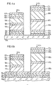
In Fig. 3a, 3b sind Aufzeichnungsträger mit Halbfiltern in Form von Schichtpaketen 311, 312 für einen ersten Farbton und von Schichtpaketen 321,322 für einen zweiten Farbton dargestellt. Das Schichtpaket 311 auf einem Schichtträger 331 besteht aus einer hochbrechenden absorptionsfreien Schicht 341, einer niedrigbrechenden absorptionsfreien Schicht 351, einer hochbrechenden absorptionsfreien Schicht 361, einer anorganischen absorptionsfreien Interferenzschicht 371 gemäss dem ersten Farbton und einer Metallschicht 381; die Schichten 341 -381 bilden den strukturbildenden Teil des Schichtpakets 311. Das Schichtpaket 321 auf dem Schichtträger 331 besteht aus einer hochbrechenden absorptionsfreien Schicht 391, einer niedrigbrechenen absorptionsfreien Schicht 401, einer hochbrechenden absorptionsfreien Schicht 411, einer anorganischen absorptionsfreien Interferenzschicht 421 gemäss dem zweiten Farbton und einer Metallschicht 431 ; die Schichten 391 -431 bilden den strukturbildenden Teil des Schichtpakets 321 . Das Schichtpaket 31 auf einem Schichtträger 332 besteht aus einer ganzflächigen hochbrechenden absorptionsfreien Schicht 342, einer ganzflächigen niedrigbrechenen absorptionsfreien Schicht 352, einer hochbrechenden absorptionsfreien Schicht 362, einer anorganischen absorptionsfreien Interferenzschicht 372 gemäss dem ersten Farbton und einer Metallschicht 382; die Schichten 362-382 bilden den strukturbildenden Teil des Schichtpakets 312, während die ganzflächigen Schichten 342, 352 nicht zur Strukturbildung beitragen. Das Schichtpaket 322 auf dem Schichtträger 332 besteht aus der ganzflächigen hochbrechenden absorptionsfreien Schicht 342, der ganzflächigen niedrigbrechenen absorptionsfreien Schicht 352, einer hochbrechenden absorptionsfreien Schicht 41z, einer anorganischen absorptionsfreien Interferenzschicht 422 gemäss dem zweiten Farbton und einer Metallschicht 432; die Schichten 412-432 bilden den strukturbildenden Teil des Schichtpakets 322, während die ganzflächigen Schichten 342, 352 nicht zur Strukturbildung beitragen. Die Aufzeichnungsträger gemäss Fig. 3a, 3b werden auf photolithographischem Weg in der vorgehend beschriebenen Weise erzeugt. Die Metallschichten 38, 43 sind teildurchlässige Schichten.3a, 3b show recording media with half filters in the form of
In Fig. 4a bis 4d sind Aufzeichnungsträger mit induzierten Transmissionsfiltern in Form von Schichtpaketen 511 -514 für einen ersten Farbton und von Schichtpaketen 521 -524 für einen zweiten Farbton dargestellt. Das Schichtpaket 511 auf einem Schichtträger 531 besteht aus einer hochbrechenden absorptionsfreien Schicht 541, einer niedrigbrechenden absorptionsfreien Schicht 551, einer hochbrechenden absorptionsfreien Schicht 561, einer ersten anorganischen absorptionsfreien Interferenzschicht 571 gemäss dem ersten Farbton, einer Metallschicht 581, einer zweiten anorganischen absorptionsfreien Interferenzschicht 591 gemäss dem ersten Farbton, einer hochbrechenden absorptionsfreien Schicht 601, einer niedrigbrechenden absorptionsfreien Schicht 611 und einer hochbrechenden absorptionsfreien Schicht 621; die Schichten 541-621 bilden den strukturbildenden Teil des Schichtpakets 511. Das Schichtpaket 521 auf dem Schichtträger 531 besteht aus einer hochbrechenden absorptionsfreien Schicht 631, einer niedrigbrechenden absorptionsfreien Schicht 641, einer hochbrechenden absorptionsfreien Schicht 651, einer ersten anorganischen absorptionsfreien Interferenzschicht 661 gemäss dem zweiten Farbton, einer Metallschicht 671, einer zweiten anorganischen absorptionsfreien Interferenzschicht 681 gemäss dem zweiten Farbton, einer hochbrechenden absorptionsfreien Schicht 691, einer niedrigbrechenden absorptionsfreie Schicht 701 und einer hochbrechenden absorptionsfreien Schicht 711; die Schichten 631 -711 bilden den strukturbildenden Teil des Schichtpakets 521.4a to 4d show recording media with induced transmission filters in the form of layer packets 51 1 -51 4 for a first color and of layer packs 52 1 -52 4 for a second color. The layer package 51 1 on a
Das Schichtpaket 512 auf einem Schichtträger 532 besteht aus einer ganzflächigen hochbrechenden absorptionsfreien Schicht 542, einer ganzflächigen niedrigbrechenden absorptionsfreien Schicht 552, einer ganzflächigen hochbrechenden absorptionsfreien Schicht 562, einer ersten anorganischen absorptionsfreien Interferenzschicht 572 gemäss dem ersten Farbton, einer Metallschicht 582, einer zweiten anorganischen absorptionsfreien Interferenzschicht 592 gemäss dem ersten Farbton, einer hochbrechenden absorptionsfreien Schicht 602, einer niedrigbrechenden absorptionsfreien Schicht 612 und einer hochbrechenden absorptionsfreien Schicht 622; die Schichten 572-622 bilden den strukturbildenden Teil des Schichtpakets 512, während die ganzflächigen Schichten 542-562 nicht zur Strukturbildung beitragen. Das Schichtpaket 522 auf dem Schichtträger 532 besteht aus der ganzflächigen hochbrechenden absorptionsfreien Schicht 542, der ganzflächigen niedrigbrechenden absorptionsfreien Schicht 552, der ganzflächigen hochbrechenden absorptionsfreien Schicht 562, einer ersten anorganischen absorptionsfreien Interferenzschicht 662 gemäss dem zweiten Farbton, einer Metallschicht 672, einer zweiten anorganischen absorptionsfreien Interferenzschicht 682 gemäss dem zweiten Farbton, einer hochbrechenden absorptionsfreien Schicht 692, einer niedrigbrechenden absorptionsfreien Schicht 702 und einer hochbrechenden absorptionsfreien Schicht 712; die Schichten 662-712 bilden den strukturbildenden Teil des Schichtpakets 522, während die ganzflächigen Schichten 542-562 nicht zur Strukturbildung beitragen. Die Aufzeichnungsträger gemäss Fig. 4a, 4b werden auf photolithographischem Weg in der vorgehend beschriebenen Weise erzeugt.The layer package 51 2 on a
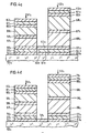
In einer anderen Ausbildung dieses Aufzeichnungsträgers wird nach Fig. 4c zur Erzeugung des ersten Farbtons auf einem Schichtträger 533, in nicht gezeigter Weise ganzflächig eine erste Photolackschicht aufgebracht und mittels der ersten Belichtungsmaske belichtet. Nach dem Entwikkein der ersten Photolackschicht werden auf dem Schichtträger 533 ganzflächig eine hochbrechende absorptionsfreie Schicht 543, eine niedrigbrechende absorptionsfreie Schicht 553, eine hochbrechende absorptionsfreie Schicht 563, eine erste anorganische absorptionsfreie Interferenzschicht 573 gemäss dem ersten Farbton, eine Metallschicht 583 und eine zweite anorganische absorptionsfreie Interferenzschicht 593 gemäss dem ersten Farbton aufgebracht. Die verbliebene erste Photolackschicht mitsamt den darüber befindlichen Schichten 543-593 wird sodann entfernt. Zur Erzeugung des zweiten Farbtons wird auf dem Schichtträger 533 ganzflächig eine zweite Photo-. lackschicht aufgebracht und mittels der zweiten Belichtungsmaske belichtet. Nach dem Entwikkein der zweiten Photolackschicht werden auf dem Schichtträger 533 ganzflächig eine hochbrechende absorptionsfreie Schicht 633, eine niedrigbrechende absorptionsfreie Schicht 643, eine hochbrechende absorptionsfreie Schicht 653, eine erste anorganische absorptionsfreie Interferenzschicht 663 gemäss dem zweiten Farbton, eine Metallschicht 673 und eine zweite anorganische absorptionsfreie Interferenzschicht 683 gemäss dem zweiten Farbton aufgebracht. Die verbliebene zweite Photolackschicht mitsamt dem darüber befindlichen Schichten 633-683 wird sodann entfernt. Auf dem Schichtträger 533 befinden sich somit die strukturbildenden Schichten 543-593 des Schichtpakets 513 für den ersten Farbton und die strukturbildenden Schichten 633-683 des Schichtpakets 523 für den zweiten Farbton. Anschliessend werden auf dem Schichtträger 533 ganzflächig eine hochbrechende absorptionsfreie Schicht 603, eine niedrigbrechende absorptionsfreie Schicht 613 und eine hochbrechende absorptionsfreie Schicht 623 aufgebracht. Die ganzflächigen Schichten 603-623 tragen nicht zur Strukturbildung bei.In another embodiment of this record carrier, a first photoresist layer is applied over the entire surface in a manner not shown in FIG. 4c to produce the first color tone on a
In einer weiteren Ausbildung dieses Aufzeichnungsträgers wird nach Fig. 4d zur Erzeugung des ersten Farbtons auf einem Schichtträger 534 in nicht gezeigter Weise ganzflächig eine erste Photolackschicht aufgebracht und mittels der ersten Belichtungsmaske belichtet. Nach dem Entwikkeln der ersten Photolackschicht werden auf dem Schichtträger 534 ganzflächig eine hochbrechende absorptionsfreie Schicht 544, eine niedrigbrechende absorptionsfreie Schicht 554, eine hochbrechende absorptionsfreie Schicht 564 und eine erste anorganische absorptionsfreie Interferenzschicht 574 gemäss dem ersten Farbton aufgebracht. Die verbliebene erste Photolackschicht mitsamt den darüber befindlichen Schichten 544-574 wird sodann entfernt. Zur Erzeugung des zweiten Farbtons wird auf dem Schichtträger 534 ganzflächig eine zweite Photolackschicht aufgebracht und mittels der zweiten Belichtungsmaske belichtet. Nach dem Entwickeln der zweiten Photolackschicht werden auf dem Schichtträger 534 ganzflächig eine hochbrechende absorptionsfreie Schicht 634, eine niedrigbrechende absorptionsfreie Schicht 644, eine hochbrechende absorptionsfreie Schicht 654 und eine erste anorganische absorptionsfreie Interferenzschicht 664 gemäss dem zweiten Farbton aufgebracht. Die verbliebene zweite Photolackschicht mitsamt den darüber befindlichen Schichten 634-664 wird sodann entfernt. Auf dem Schichtträger 534 befinden sich somit der erste Teil der strukturbildenden Schichten 544-574 des Schichtpakets 514 für den ersten Farbton und der erste Teil der strukturbildenden Schichten 634-664 des Schichtpakets 524 für den zweiten Farbton. Anschliessend werden auf dem Schichtträger 534 ganzflächig eine Metallschicht 584, die nicht zur Strukturbildung beiträgt, und darüber zur Erzeugung des ersten Farbtons eine dritte Photolackschicht aufgebracht, die mittels der ersten Belichtungsmaske belichtet wird. Nach dem Entwickeln der dritten Photolackschicht werden auf der Metallschicht 584 ganzflächig eine zweite anorganische absorptionsfreie Interferenzschicht 594 gemäss dem ersten Farbton, eine hochbrechende absorptionsfreie Schicht 604, eine niedrigbrechende absorptionsfreie Schicht 614 und eine hochbrechende absorptionsfreie Schicht 624 aufgebracht. Die verbliebene dritte Photolackschicht mitsamt den darüber befindlichen Schichten 594-624 wird sodann entfernt. Zur Erzeugung des zweiten Farbtons wird auf der Metallschicht 584 anschliessend ganzflächig eine vierte Photolackschicht aufgebracht und mittels der zweiten Belichtungsmaske belichtet. Nach dem Entwickeln der vierten Photolackschichtwerden auf der Metallschicht 584 ganzflächig eine zweite anorganische absorptionsfreie Interferenzschicht 684 gemäss dem zweiten Farbton, eine hochbrechende absorptionsfreie Schicht 694, eine niedrigbrechende absorptionsfreie Schicht 704 und eine hochbrechende absorptionsfreie Schicht 714 aufgebracht. Die verbliebene vierte Photolackschicht mitsamt den darüber befindlichen Schichten 684-714 wird sodann entfernt. Auf der Metallschicht 584 befinden sich somit der zweite Teil der strukturbildenden Schichten 594-624 des Schichtpakets 514 für den ersten Farbton und der zweite Teil der strukturbildenden Schichten 684-714 des Schichtpakets 524 für den zweiten Farbton. Die Metallschichten 58, 67 sind teildurchlässig Schichten.In a further embodiment of this record carrier, a first photoresist layer is applied over the entire surface in a manner not shown in FIG. 4d to produce the first color tone on a
In Fig. 5a, 5b sind Aufzeichnungsträger mit Kantenfiltern in Form von Schichtpaketen 811,812 für einen ersten Farbton und von Schichtpaketen 821, 822 für einen zweiten Farbton dargestellt. Das Schichtpaket 81, auf einem Schichtträger 831 nach Fig. 5a besteht aus zwei übereinanderliegenden Kantenfiltern 841-881; 891-931, die aus hochbrechenden absorptionsfreien Schichten 841, 861, 881; 891, 911, 93, bestehen, zwischen denen sich niedrigbrechende absorptionsfreie Schichten 851, 871; 901, 921 befinden. Das Schichtpaket 821 auf dem Schichtträger 83, besteht aus zwei übereinanderliegenden Kantenfiltern 941 -981 ; 991 -1031, die aus hochbrechenden absorptionsfreien Schichten 941, 961, 981; 991, 1011, 1031 bestehen, zwischen denen sich niedrigbrechende absorptionsfreie Schichten 951, 971; 1001,1021 befinden. Die Schichten 841-931 der beiden Kantenfilter 841 -881; 891 -931 bilden den strukturbildenden Teil des Schichtpakets 811 und die Schichten 941 -1031 der beiden Kantenfilter 941-981 ; 991-1031 den strukturbildenden Teil des Schichtpakets 821.5a, 5b are recording media with edge filters in the form of
Das Schichtpaket 81 2 auf einem Schichtträger 832 nach Fig. 5b besteht aus zwei übereinanderliegenden Kantenfiltern 842-882; 892-932, von denen das Kantenfilter 842-882 aus ganzflächigen hochbrechenden absorptionsfreien Schichten 842, 862, 882, zwischen denen sich ganzflächige niedrigbrechende absorptionsfreie Schichten 852, 872 befinden, und das Kantenfilter 892-932 aus hochbrechenden absorptionsfreien Schichten 892, 912, 932 bestehen, zwischen denen sich niedrigbrechende absorptionsfreie Schichten 902, 922 befinden; das Kantenfilter 902-932 bildet den strukturbildenden Teil des Schichtpakets 812. Das Schichtpaket 822 auf dem Schichtträger 832 besteht aus dem ganzflächigen Kantenfilter 842-882, über dem sich ein Kantenfilter 992-1032 befindet, das aus hochbrechenden absorptionsfreien Schichten 992,1012,1032 besteht, zwischen denen sich niedrigbrechende absorptionsfreie Schichten 1002, 1022 befinden. Das Kantenfilter 992-1032 bildet den strukturbildenden Teil des Schichtpakets 822; das ganzflächige Kantenfilter 842-882 trägt nicht zur Strukturbildung der Schichtpakete 812, 822 bei.The
Bei den Filtern 1, 2; 11, 12; 31, 32; 51, 52 werden die ersten und zweiten Farbtöne durch die optischen Dicken der Interferenzschichten 5, 8; 17, 24; 37,42; 57, 59, 66, 68 und die Sättigung dieser Farbtöne durch das Reflexionsvermögen der Metallschichten 4, 6, 7, 9; 38, 43; 58, 67 bzw. der hochbrechenden Schichten 14, 16, 18, 20, 21, 23, 25, 27; 34, 36, 39, 41; 54, 56, 60, 62, 63, 65, 69, 71 und der niedrigbrechenden Schichten 15, 19, 22, 26; 35, 40; 55, 61, 64, 70 bestimmt.
Bei einem Kantenfilter (Reflektor) fällt der spektrale Bereich hoher Transmission über eine steile Flanke zu einem spektralen Bereich niedriger Transmission ab. Die optischen Schichtdicken der hochbrechenden und niedrigbrechenden Schichten eines Kantenfilters betragen λ/4, wobei λ die grösste Wellenlänge der geringsten Transmission des Kantenfilters bedeutet. Die Kantenfilter 841-881; 941-981 nach Fig. 5a mögen im spektralen Bereich der zu erzeugenden beiden Farbtöne eine mit zunehmender Wellenlänge ansteigende Flanke der Transmission und die Kantenfilter 891 -931; 99, -1031 in diesem Bereich eine abfallende Flanke der Transmission aufweisen; durch Überlagerung der Kantenfilter 841-881; 941-981 mit den Kantenfiltern 891-931; 991-1031 wird ein Transmissionsmaximum für die beiden gewünschten Farbtöne erzielt.In the case of an edge filter (reflector), the spectral range of high transmission drops over a steep flank to a spectral range of low transmission. The optical layer thicknesses of the high-index and low-index layers of an edge filter are λ / 4, where λ means the greatest wavelength of the lowest transmission of the edge filter. The edge filters 84 1 -88 1 ; 94 1 -98 1 according to FIG. 5a, in the spectral range of the two color tones to be generated, a flank of the transmission rising with increasing wavelength and the edge filters 89 1 -93 1 ; 99, -103 1 have a falling edge of the transmission in this area; by overlaying the edge filters 84 1 -88 1 ; 94 1 -98 1 with the edge filters 89 1 -93 1 ; 99 1 -103 1 , a transmission maximum is achieved for the two desired colors.
Bei einem bestimmten Verhältnis von Schichtdicke der überlagerten Kantenfilter zum Durchmesser der Feinstruktur können jedoch Schwierigkeiten bei der Entfernung der verbliebenen Photolackschicht mitsamt den darauf befindlichen Kantenfiltern auftreten. Es wird daher vorgeschlagen, gemäss Fig. 5b den unteren Kantenfilter 842-882 ganzflächig auszubilden und die überlagerten Kantenfilter 892- 932; 992-1032 allein zu strukturieren. Der ganzflächige Kantenfilter 842-882 muss in bestimmten Wellenlängenbereichen eine möglichst hohe und konstante Transmission besitzen, was durch eine Variation der optischen Schichtdicken der hochbrechenden und niedrigbrechenden Schichten 842-882 erreicht wird. Vorzugsweise unterscheiden sich dabei die optischen Schichtdicken etwa im Bereich von ±10% vom Betrag λ/4.With a certain ratio of the layer thickness of the superimposed edge filters to the diameter of the fine structure, difficulties can arise in removing the remaining photoresist layer together with the edge filters located thereon. It is therefore proposed, according to FIG. 5b, to design the lower edge filter 84 2 -88 2 over the entire surface and the superimposed edge filter 89 2 - 93 2 ; 99 2 -103 2 to be structured alone. The entire-area edge filter 84 2 -88 2 must have a transmission that is as high and constant as possible in certain wavelength ranges, which is achieved by varying the optical layer thicknesses of the high-index and low-index layers 84 2 -88 2 . The optical layer thicknesses preferably differ approximately in the range of ± 10% from the amount λ / 4.
Derartige Schichtpakete können auch aus einer Kombination von Filtern 1, 2; 11, 12; 31, 32; 51, 52; 81, 82 bestehen. In Fig. 6a, 6b sind Aufzeichnungsträger mit Kantenfiltern und überlagerten metall-dielektrichen Interferenzfiltern in Form von Schichtpaketen 1111, 1112 für einen ersten Farbton und von Schichtpaketen 1121, 1122 für einen zweiten Farbton dargestellt. Das Schichtpaket 1111 auf einem Schichtträger 1131 nach Fig. 6a besteht aus einem Kantenfilter 1141 -1181 mit hochbrechenden absorptionsfreien Schichten 1141, 1161, 1181, zwischen denen sich niedrigbrechende absorptionsfreie Schichten 1151,1171 befinden, und aus einem metall-dielektrischen Interferenzfilter 1191-1211 mit einer Interferenzschicht 1201, die auf beiden Seiten durch anorganische spiegelnde Schichten 1191, 1211 begrenzt ist. Das Schichtpaket 1121 auf dem Schichtträger 1131 besteht aus einem Kantenfilter 1221-1281 mit hochbrechenden absorptionsfreien Schichten 1221, 1241, 1261, 1281, zwischen denen sich niedrigbrechende absorptionsfreie Schichten 1231,1251,1271 befinden, und aus einem metall- dielektrischen Interferenzfilter 1291-1311 mit einer Interferenzschicht 1301, die auf beiden Seiten durch anorganische spiegelnde Schichten 1291,1311 begrenzt ist. Die Schichten 1141 -1211 bilden den strukturbildenden Teil des Schichtpakets 1111 und die Schichten 1221 -1311 den strukturbildenden Teil des Schichtpakets 1121.Layer packets of this type can also be made from a combination of
Das Schichtpaket 1112 auf einem Schichtträger 1132 nach Fig. 6b besteht aus einem Kantenfilter 1142-1182 mit ganzflächigen hochbrechenden absorptionsfreien Schichten 1142, 1162, 1182, zwischen denen sich ganzflächige niedrigbrechende absorptionsfreie Schichten 1152, 1172 befinden, und aus einem metall-dielektrischen Interferenzfilter 1192-1212 mit einer Interferenzschicht 1202, die auf beiden Seiten durch anorganische spiegelnde Schichten 1192-1212 begrenzt ist; das metall-dielektrische Interferenzfilter 1192-1212 bildet den strukturbildenden Teil des Schichtpakets 1112. Das Schichtpaket 1122 auf dem Schichtträger 1132 besteht aus den ganzflächigen Schichten 1142-1182, aus einer niedrigbrechenden absorptionsfreien Schicht 1272, aus einer hochbrechenden absorptionsfreien Schicht 1282 und aus einem metall-dielektrischen Interferenzfilter 1292-1312 mit einer Interferenzschicht 1302, die auf beiden Seiten durch anorganische spiegelnde Schichten 1292, 1312 begrenzt ist; die Schichten 127z, 1282 und das metall-dielektrische Interferenzfilter 1292-1312 bilden den strukturbildenden Teil des Schichtpakets 1122.The
Die anorganischen spiegelnden Schichten 4, 6, 7, 9; 38, 43; 58, 67; 119,121,129,131 bestehen aus Ag, Cr, Au, AI oder aus einer Kombination dieser Materialien, die Interferenzschichten 5, 8; 17, 24; 37, 42; 57, 59, 66, 68; 120, 130 aus MgF2, Si02, Al2O3. Fe203 oder aus Mischungen dieser Materialien, die hochbrechenden Schichten 14, 16, 18, 20, 21, 23, 25, 27; 34, 36, 39, 41; 54, 56, 60, 62, 63, 65, 69, 71; 84, 86, 88, 89, 91, 93, 94, 96, 98, 99, 101, 103; 114, 116, 118, 122, 124, 126, 128 aus Ti02, Zr02, Hf02, Nd203 oder aus Mischungen dieser Materialien und die niedrigbrechenden Schichten 15, 19, 22, 26; 35, 40; 55, 61, 64, 70; 85, 87, 90, 92, 95, 97, 100, 102; 115, 117,123,125,127 aus MgF2, Si02, Al2O3, Fe203 oder aus Mischungen dieser Materialien. Der Schichtträger 3; 13; 33; 53; 83; 113 kann aus durchsichtigem Material oder aus undurchsichtigem Material mit spiegelnder Oberfläche bestehen.The inorganic reflective layers 4, 6, 7, 9; 38, 43; 58, 67; 119,121,129,131 consist of Ag, Cr, Au, Al or a combination of these materials, the interference layers 5, 8; 17, 24; 37, 42; 57, 59, 66, 68; 120, 130 made of MgF 2 , Si0 2 , Al 2 O 3 . Fe20 3 or from mixtures of these materials, the high refractive index layers 14, 16, 18, 20, 21, 23, 25, 27; 34, 36, 39, 41; 54, 56, 60, 62, 63, 65, 69, 71; 84, 86, 88, 89, 91, 93, 94, 96, 98, 99, 101, 103; 114, 116, 118, 122, 124, 126, 128 made of Ti0 2 , Zr0 2 , Hf0 2 , Nd 2 0 3 or from mixtures of these materials and the low-
Die Schichtpakete 1, 2; 11, 12; 31, 32; 51, 52; 81, 82; 111, 112 und/oder strukturbildende Teile dieser Schichtpakete 1, 2; 11, 12; 31, 32; 51, 52; 81, 82; 111, 112 werden bevorzugt auf photolithographischem Wege nacheinander- und zwar in der Reihenfolge der Farbtöne der Feinstruktur - örtlich voneinander getrennt auf dem Schichtträger 3; 13; 33; 53; 83; 113 aufgebracht. Neben dem vorgehend beschriebenen photolithographischen Verfahren können die Schichtpakete und/ oder die strukturbildenden Teile dieser Schichtpakete auf photolithographischem Wege mittels nasschemischer Ätzverfahren oder physikalischer Ätzverfahren wie lonenstrahlätzen, Sputterätzen, Plasmaätzen oder reaktives lonenätzen auf dem Schichtträger erzeugt werden. Des weiteren können die Schichtpakete und/oder die strukturbildenden Teile dieser Schichtpakete mittels jeweils einer Bedampfungsmaske oder mittels eines gesteuerten Teilchenstrahls (Elektronenstrahl, lonenstrahl etc.) hergestellt werden.The layer packages 1, 2; 11, 12; 31, 32; 51, 52; 81, 82; 111, 112 and / or structure-forming parts of these
Auf einem Schichtträger können auf einem Teil Schichtpakete mit teilweise ganzflächigen Schichten und auf einem anderen Teil Schichtpakete ohne ganzflächige Schichten - auch mit unterschiedlichen Herstellungsverfahren - erzeugt werden. Zwischen aneinandergrenzenden unterschiedlichen Schichtpaketen, die nacheinander erzeugt worden sind, ist ein Grenzbereich definiert, der eine örtliche Trennung dieser Schichtpakete darstellt.Layer packs with partially full-area layers can be produced on one layer support and layer packs without full-area layers on another part - also with different manufacturing processes. A border area is defined between adjacent different layer packets that have been generated one after the other, which represents a local separation of these layer packets.
Das Aufbringen der Schichten der Schichtpakete 1, 2; 11, 12; 31, 32; 51, 52; 81, 82; 111, 112 kann beispielsweise durch Aufdampfen, Sputtern, lonenplattieren und Ausscheiden aus der Dampfphase erfolgen.The application of the layers of the layer packages 1, 2; 11, 12; 31, 32; 51, 52; 81, 82; 111, 112 can be carried out, for example, by vapor deposition, sputtering, ion plating and separation from the vapor phase.
Die erfindungsgemässen Aufzeichnungsträger weisen insbesondere den Vorteil einer verbesserten Farbtonreinheit und Farbtonsättigung sowie einer Verminderung des Ausschusses auf.The recording media according to the invention have in particular the advantage of improved color purity and color saturation and a reduction in rejects.
Der vorgeschlagene Aufzeichnungsträger findet bevorzugt Verwendung zur Aufzeichnung mehrfarbiger Mikrolandkarten.The proposed recording medium is preferably used for recording multi-colored micro-maps.
Claims (28)
Priority Applications (1)
| Application Number | Priority Date | Filing Date | Title |
|---|---|---|---|
| AT82109176T ATE14484T1 (en) | 1981-12-04 | 1982-10-05 | RECORD CARRIER WITH A MULTICOLORED FINE STRUCTURE, ESPECIALLY IN THE FORM OF A MICROMAP, AND METHOD FOR MANUFACTURING THE RECORD CARRIER. |
Applications Claiming Priority (2)
| Application Number | Priority Date | Filing Date | Title |
|---|---|---|---|
| DE3147985 | 1981-12-04 | ||
| DE3147985A DE3147985C2 (en) | 1981-12-04 | 1981-12-04 | Process for the production of a recording medium with a multicolored fine structure |
Publications (2)
| Publication Number | Publication Date |
|---|---|
| EP0081055A1 EP0081055A1 (en) | 1983-06-15 |
| EP0081055B1 true EP0081055B1 (en) | 1985-07-24 |
Family
ID=6147857
Family Applications (1)
| Application Number | Title | Priority Date | Filing Date |
|---|---|---|---|
| EP82109176A Expired EP0081055B1 (en) | 1981-12-04 | 1982-10-05 | Record carrier with a multi-coloured micro-image, especially in the form of a micro map, and process for the manufacture of this record carrier |
Country Status (8)
| Country | Link |
|---|---|
| US (1) | US4522862A (en) |
| EP (1) | EP0081055B1 (en) |
| JP (1) | JPS58144804A (en) |
| AT (1) | ATE14484T1 (en) |
| BR (1) | BR8207025A (en) |
| DE (1) | DE3147985C2 (en) |
| IL (1) | IL67365A (en) |
| ZA (1) | ZA828896B (en) |
Families Citing this family (13)
| Publication number | Priority date | Publication date | Assignee | Title |
|---|---|---|---|---|
| JPS60186804A (en) * | 1984-03-06 | 1985-09-24 | Hisanori Bando | Film having periodic multi-layered structure |
| JPH0672298B2 (en) * | 1984-03-09 | 1994-09-14 | 京都大学 | Oxide multilayer film having periodicity |
| JPH0797216B2 (en) * | 1986-10-29 | 1995-10-18 | インタ−ナショナル・ビジネス・マシ−ンズ・コ−ポレ−ション | Mask manufacturing method |
| US4923772A (en) * | 1986-10-29 | 1990-05-08 | Kirch Steven J | High energy laser mask and method of making same |
| US4713315A (en) * | 1986-12-09 | 1987-12-15 | Smith David V | Wire tag etching system |
| US4979803A (en) * | 1989-02-02 | 1990-12-25 | Eastman Kodak Company | Color filter array for area image sensors |
| US4956555A (en) * | 1989-06-30 | 1990-09-11 | Rockwell International Corporation | Multicolor focal plane arrays |
| JP2599513B2 (en) * | 1990-06-25 | 1997-04-09 | インターナショナル・ビジネス・マシーンズ・コーポレイション | Ablation mask |
| US5217832A (en) * | 1992-01-23 | 1993-06-08 | The Walt Disney Company | Permanent color transparencies on single substrates and methods for making the same |
| DE10150099A1 (en) * | 2001-10-11 | 2003-04-17 | Heidenhain Gmbh Dr Johannes | Production of a measuring rod used for electrical position measuring device comprises applying spacer layer on first reflecting layer, applying second reflecting layer, and structuring second reflecting layer by electron beam lithography |
| JP4125158B2 (en) * | 2003-02-28 | 2008-07-30 | キヤノン株式会社 | Reflector and optical instrument using the same |
| JP4828612B2 (en) | 2007-06-01 | 2011-11-30 | 株式会社ミツトヨ | Reflective encoder, scale thereof, and method of manufacturing scale |
| CN102804005B (en) * | 2009-06-17 | 2016-07-06 | 皇家飞利浦电子股份有限公司 | The interference filter with highly transmissive and big suppression scope for micro spectrometer |
Family Cites Families (9)
| Publication number | Priority date | Publication date | Assignee | Title |
|---|---|---|---|---|
| FR1584726A (en) * | 1967-02-02 | 1970-01-02 | ||
| US3727233A (en) * | 1969-11-06 | 1973-04-10 | Gijutsuin K Int Trade Ind | Method of recording an electronic image |
| GB1545048A (en) * | 1976-05-27 | 1979-05-02 | Rca Corp | Simplified diffractive colour filtering technique |
| US4155627A (en) * | 1976-02-02 | 1979-05-22 | Rca Corporation | Color diffractive subtractive filter master recording comprising a plurality of superposed two-level relief patterns on the surface of a substrate |
| DE2658623C2 (en) * | 1976-12-23 | 1982-07-29 | Dr. Johannes Heidenhain Gmbh, 8225 Traunreut | Recording media and process for its manufacture |
| US4124473A (en) * | 1977-06-17 | 1978-11-07 | Rca Corporation | Fabrication of multi-level relief patterns in a substrate |
| DE2903641C2 (en) * | 1979-01-31 | 1982-11-11 | Dr. Johannes Heidenhain Gmbh, 8225 Traunreut | Process for producing a recording medium with a pattern which appears in at least two different colors when irradiated with light |
| DE2952230C2 (en) * | 1979-12-22 | 1984-02-02 | Dr. Johannes Heidenhain Gmbh, 8225 Traunreut | Process for producing a recording medium with a pattern which appears in at least two different colors when irradiated with light |
| DE3040489A1 (en) * | 1980-10-28 | 1982-05-27 | Dr. Johannes Heidenhain Gmbh, 8225 Traunreut | RECORD CARRIER WITH A HIGH INFORMATION DENSITY RECORD |
-
1981
- 1981-12-04 DE DE3147985A patent/DE3147985C2/en not_active Expired
-
1982
- 1982-10-05 EP EP82109176A patent/EP0081055B1/en not_active Expired
- 1982-10-05 AT AT82109176T patent/ATE14484T1/en active
- 1982-11-30 US US06/445,557 patent/US4522862A/en not_active Expired - Fee Related
- 1982-11-30 IL IL67365A patent/IL67365A/en unknown
- 1982-12-01 JP JP57209482A patent/JPS58144804A/en active Granted
- 1982-12-03 ZA ZA828896A patent/ZA828896B/en unknown
- 1982-12-03 BR BR8207025A patent/BR8207025A/en not_active IP Right Cessation
Also Published As
| Publication number | Publication date |
|---|---|
| IL67365A (en) | 1986-02-28 |
| JPS58144804A (en) | 1983-08-29 |
| ZA828896B (en) | 1983-10-26 |
| JPS6139641B2 (en) | 1986-09-04 |
| EP0081055A1 (en) | 1983-06-15 |
| BR8207025A (en) | 1983-10-11 |
| US4522862A (en) | 1985-06-11 |
| DE3147985C2 (en) | 1986-03-13 |
| IL67365A0 (en) | 1983-03-31 |
| ATE14484T1 (en) | 1985-08-15 |
| DE3147985A1 (en) | 1983-06-16 |
Similar Documents
| Publication | Publication Date | Title |
|---|---|---|
| EP0081055B1 (en) | Record carrier with a multi-coloured micro-image, especially in the form of a micro map, and process for the manufacture of this record carrier | |
| DE2658623C2 (en) | Recording media and process for its manufacture | |
| DE2602790C2 (en) | Method for subtractive color filtering by diffraction, color filter device for carrying out the method and use of such a color filter device | |
| DE4113968A1 (en) | Mask structure for semiconductor component prodn. - has transparent support plate on which are periodically set given groups of component structures with phase shift structures | |
| EP2453269B1 (en) | Thin film element with multi-layer structure | |
| DE10362217B4 (en) | Optical diffraction elements and method of making the same | |
| DE4448052B4 (en) | Mask for projecting structure onto semiconductor wafer - has steps which correspond to step structure on semiconductor wafer, e.g. formed using transparent layer structure | |
| DE102005043338A1 (en) | Translucent substrate for mask blank and mask blank | |
| US11762137B2 (en) | Photo resist as opaque aperture mask on multispectral filter arrays | |
| DE10064143A1 (en) | Anti-reflection coating for ultraviolet light at large angles of incidence | |
| KR0186067B1 (en) | Gradation mask and its manufacture | |
| DE4215210C2 (en) | Manufacturing method for a phase shift mask | |
| DE69729381T2 (en) | METHOD FOR PRODUCING AN APERTURE AND APRIL SO MADE THEREFOR | |
| DE10349087A1 (en) | Half-tone-type phase shift mask blank manufacturing method involves sputtering reactive gas onto substrate, to form half-tone film with desired optical characteristic, irrespective of change of gas flow amount | |
| US4182647A (en) | Process of producing stripe filter | |
| DE4318163C2 (en) | Process for repairing a defect in a phase shift structuring | |
| EP1998195B1 (en) | Interference filter and method for its production | |
| EP0037529A1 (en) | Method of manufacturing a photodetector with a striped colour filter | |
| DE4415136C2 (en) | Method of making a lithography mask | |
| DE3040489C2 (en) | ||
| EP4031380B1 (en) | Method for producing a security element, and security element | |
| DE4420417C2 (en) | Method for producing a mask for producing a pattern on a semiconductor component | |
| KR950019780A (en) | Manufacturing method of color filter | |
| DE60036185T2 (en) | Lithographic apparatus with filter | |
| DE3013142A1 (en) | Photoreceptor prodn. with multi-chroitic colour strip filter - useful for coding and decoding using photoresist and vapour deposition of interference layers |
Legal Events
| Date | Code | Title | Description |
|---|---|---|---|
| PUAI | Public reference made under article 153(3) epc to a published international application that has entered the european phase |
Free format text: ORIGINAL CODE: 0009012 |
|
| 17P | Request for examination filed |
Effective date: 19821012 |
|
| AK | Designated contracting states |
Designated state(s): AT CH FR GB IT LI NL SE |
|
| ITF | It: translation for a ep patent filed |
Owner name: VETTOR GALLETTI DI SAN CATALDO |
|
| GRAA | (expected) grant |
Free format text: ORIGINAL CODE: 0009210 |
|
| STAA | Information on the status of an ep patent application or granted ep patent |
Free format text: STATUS: THE PATENT HAS BEEN GRANTED |
|
| AK | Designated contracting states |
Designated state(s): AT CH FR GB IT LI NL SE |
|
| REF | Corresponds to: |
Ref document number: 14484 Country of ref document: AT Date of ref document: 19850815 Kind code of ref document: T |
|
| ET | Fr: translation filed | ||
| PLBE | No opposition filed within time limit |
Free format text: ORIGINAL CODE: 0009261 |
|
| 26N | No opposition filed | ||
| PGFP | Annual fee paid to national office [announced via postgrant information from national office to epo] |
Ref country code: FR Payment date: 19900914 Year of fee payment: 9 |
|
| PGFP | Annual fee paid to national office [announced via postgrant information from national office to epo] |
Ref country code: GB Payment date: 19900917 Year of fee payment: 9 |
|
| PGFP | Annual fee paid to national office [announced via postgrant information from national office to epo] |
Ref country code: CH Payment date: 19900918 Year of fee payment: 9 |
|
| PGFP | Annual fee paid to national office [announced via postgrant information from national office to epo] |
Ref country code: SE Payment date: 19900920 Year of fee payment: 9 |
|
| PGFP | Annual fee paid to national office [announced via postgrant information from national office to epo] |
Ref country code: AT Payment date: 19900924 Year of fee payment: 9 |
|
| ITTA | It: last paid annual fee | ||
| PGFP | Annual fee paid to national office [announced via postgrant information from national office to epo] |
Ref country code: NL Payment date: 19901031 Year of fee payment: 9 |
|
| PG25 | Lapsed in a contracting state [announced via postgrant information from national office to epo] |
Ref country code: GB Effective date: 19911005 Ref country code: AT Effective date: 19911005 |
|
| PG25 | Lapsed in a contracting state [announced via postgrant information from national office to epo] |
Ref country code: SE Effective date: 19911006 |
|
| PG25 | Lapsed in a contracting state [announced via postgrant information from national office to epo] |
Ref country code: LI Effective date: 19911031 Ref country code: CH Effective date: 19911031 |
|
| PG25 | Lapsed in a contracting state [announced via postgrant information from national office to epo] |
Ref country code: NL Effective date: 19920501 |
|
| GBPC | Gb: european patent ceased through non-payment of renewal fee | ||
| NLV4 | Nl: lapsed or anulled due to non-payment of the annual fee | ||
| PG25 | Lapsed in a contracting state [announced via postgrant information from national office to epo] |
Ref country code: FR Effective date: 19920630 |
|
| REG | Reference to a national code |
Ref country code: CH Ref legal event code: PL |
|
| REG | Reference to a national code |
Ref country code: FR Ref legal event code: ST |
|
| EUG | Se: european patent has lapsed |
Ref document number: 82109176.6 Effective date: 19920510 |