EP0081024A1 - Einrichtung zum wahlweisen Antrieb von Maschinen oder Vorrichtungen durch die Zapfwelle eines landwirtschaftlichen Schleppers - Google Patents
Einrichtung zum wahlweisen Antrieb von Maschinen oder Vorrichtungen durch die Zapfwelle eines landwirtschaftlichen Schleppers Download PDFInfo
- Publication number
- EP0081024A1 EP0081024A1 EP81401788A EP81401788A EP0081024A1 EP 0081024 A1 EP0081024 A1 EP 0081024A1 EP 81401788 A EP81401788 A EP 81401788A EP 81401788 A EP81401788 A EP 81401788A EP 0081024 A1 EP0081024 A1 EP 0081024A1
- Authority
- EP
- European Patent Office
- Prior art keywords
- shaft
- input shaft
- output
- output shafts
- grooves
- Prior art date
- Legal status (The legal status is an assumption and is not a legal conclusion. Google has not performed a legal analysis and makes no representation as to the accuracy of the status listed.)
- Granted
Links
- 230000007246 mechanism Effects 0.000 title claims abstract description 39
- 230000008878 coupling Effects 0.000 claims description 4
- 238000010168 coupling process Methods 0.000 claims description 4
- 238000005859 coupling reaction Methods 0.000 claims description 4
- 238000006073 displacement reaction Methods 0.000 claims description 4
- 210000000056 organ Anatomy 0.000 claims 1
- 238000005096 rolling process Methods 0.000 description 5
- 241000282472 Canis lupus familiaris Species 0.000 description 3
- 230000006835 compression Effects 0.000 description 3
- 238000007906 compression Methods 0.000 description 3
- 230000009471 action Effects 0.000 description 2
- 230000005540 biological transmission Effects 0.000 description 2
- 230000003100 immobilizing effect Effects 0.000 description 2
- 230000000717 retained effect Effects 0.000 description 2
- 241001124569 Lycaenidae Species 0.000 description 1
- 230000000694 effects Effects 0.000 description 1
- 239000004459 forage Substances 0.000 description 1
- 230000013011 mating Effects 0.000 description 1
- 230000004048 modification Effects 0.000 description 1
- 238000012986 modification Methods 0.000 description 1
Images
Classifications
-
- A—HUMAN NECESSITIES
- A01—AGRICULTURE; FORESTRY; ANIMAL HUSBANDRY; HUNTING; TRAPPING; FISHING
- A01B—SOIL WORKING IN AGRICULTURE OR FORESTRY; PARTS, DETAILS, OR ACCESSORIES OF AGRICULTURAL MACHINES OR IMPLEMENTS, IN GENERAL
- A01B71/00—Construction or arrangement of setting or adjusting mechanisms, of implement or tool drive or of power take-off; Means for protecting parts against dust, or the like; Adapting machine elements to or for agricultural purposes
- A01B71/06—Special adaptations of coupling means between power take-off and transmission shaft to the implement or machine
-
- B—PERFORMING OPERATIONS; TRANSPORTING
- B60—VEHICLES IN GENERAL
- B60K—ARRANGEMENT OR MOUNTING OF PROPULSION UNITS OR OF TRANSMISSIONS IN VEHICLES; ARRANGEMENT OR MOUNTING OF PLURAL DIVERSE PRIME-MOVERS IN VEHICLES; AUXILIARY DRIVES FOR VEHICLES; INSTRUMENTATION OR DASHBOARDS FOR VEHICLES; ARRANGEMENTS IN CONNECTION WITH COOLING, AIR INTAKE, GAS EXHAUST OR FUEL SUPPLY OF PROPULSION UNITS IN VEHICLES
- B60K17/00—Arrangement or mounting of transmissions in vehicles
- B60K17/28—Arrangement or mounting of transmissions in vehicles characterised by arrangement, location, or type of power take-off
-
- B—PERFORMING OPERATIONS; TRANSPORTING
- B60—VEHICLES IN GENERAL
- B60K—ARRANGEMENT OR MOUNTING OF PROPULSION UNITS OR OF TRANSMISSIONS IN VEHICLES; ARRANGEMENT OR MOUNTING OF PLURAL DIVERSE PRIME-MOVERS IN VEHICLES; AUXILIARY DRIVES FOR VEHICLES; INSTRUMENTATION OR DASHBOARDS FOR VEHICLES; ARRANGEMENTS IN CONNECTION WITH COOLING, AIR INTAKE, GAS EXHAUST OR FUEL SUPPLY OF PROPULSION UNITS IN VEHICLES
- B60K25/00—Auxiliary drives
- B60K25/06—Auxiliary drives from the transmission power take-off
-
- Y—GENERAL TAGGING OF NEW TECHNOLOGICAL DEVELOPMENTS; GENERAL TAGGING OF CROSS-SECTIONAL TECHNOLOGIES SPANNING OVER SEVERAL SECTIONS OF THE IPC; TECHNICAL SUBJECTS COVERED BY FORMER USPC CROSS-REFERENCE ART COLLECTIONS [XRACs] AND DIGESTS
- Y10—TECHNICAL SUBJECTS COVERED BY FORMER USPC
- Y10T—TECHNICAL SUBJECTS COVERED BY FORMER US CLASSIFICATION
- Y10T74/00—Machine element or mechanism
- Y10T74/19—Gearing
- Y10T74/19023—Plural power paths to and/or from gearing
- Y10T74/19074—Single drive plural driven
- Y10T74/19079—Parallel
- Y10T74/19088—Bevel
-
- Y—GENERAL TAGGING OF NEW TECHNOLOGICAL DEVELOPMENTS; GENERAL TAGGING OF CROSS-SECTIONAL TECHNOLOGIES SPANNING OVER SEVERAL SECTIONS OF THE IPC; TECHNICAL SUBJECTS COVERED BY FORMER USPC CROSS-REFERENCE ART COLLECTIONS [XRACs] AND DIGESTS
- Y10—TECHNICAL SUBJECTS COVERED BY FORMER USPC
- Y10T—TECHNICAL SUBJECTS COVERED BY FORMER US CLASSIFICATION
- Y10T74/00—Machine element or mechanism
- Y10T74/19—Gearing
- Y10T74/19642—Directly cooperating gears
- Y10T74/1966—Intersecting axes
- Y10T74/19665—Bevel gear type
-
- Y—GENERAL TAGGING OF NEW TECHNOLOGICAL DEVELOPMENTS; GENERAL TAGGING OF CROSS-SECTIONAL TECHNOLOGIES SPANNING OVER SEVERAL SECTIONS OF THE IPC; TECHNICAL SUBJECTS COVERED BY FORMER USPC CROSS-REFERENCE ART COLLECTIONS [XRACs] AND DIGESTS
- Y10—TECHNICAL SUBJECTS COVERED BY FORMER USPC
- Y10T—TECHNICAL SUBJECTS COVERED BY FORMER US CLASSIFICATION
- Y10T74/00—Machine element or mechanism
- Y10T74/19—Gearing
- Y10T74/19642—Directly cooperating gears
- Y10T74/19688—Bevel
- Y10T74/19693—Motor vehicle drive
Definitions
- the present invention relates to a mechanism for the selective drive of machines or devices from the PTO shaft of an agricultural tractor.
- a single output shaft has therefore been provided for the aforementioned drive mechanism, ensuring the drive of the harvester-chopper-loader, by giving up a possibility of driving the or devices fitted to the trailer, or a fixed casing covering the second output shaft, which can be connected normally to the trailer, has been adapted on the existing mechanism, in this second case avoiding a more profound modification of the system.
- ! ' e object of the invention is to create a mechanism of the general type considered, arranged to oppose any simultaneous drive of the two output shafts of the mechanism while allowing their selective drive.
- the invention relates to a mechanism of the above-mentioned type, comprising an input shaft which can be connected to the power take-off shaft of an agricultural tractor and driven in permanent rotation during work, and two output shafts, characterized in that this input shaft, on the one hand, and these output shafts or members connected in rotation to these, on the other hand, have profilings which can be brought directly or indirectly into engagement, and in this that there is provided a movable control member between two selective positions in each of which a coming in direct or indirect engagement is achieved between the profiling of the input shaft and those of one of the output shafts, while the other output shaft profiles are uncoupled from those of the input shaft.
- One of the output shafts connected to a harvester-chopper-loader, then extends transversely to the input shaft, and the other output shaft extends in the extension of the input shaft and is connected to a device fitted to a trailer coupled to the agricultural tractor.
- the mechanism comprises, on the end part of the input shaft, a sliding zone on which is slidably mounted a sliding sleeve or similar member integral in rotation with the input shaft, this sleeve having grooves or similar profiling towards its ends, and the two output shafts or members connected to them are idly mounted on journals provided on the input shaft on either side of the zcne forming slide, these output shafts or these members connected to them also having equivalent grooves or profiling with which the equivalent grooves or profiling placed opposite the sliding sleeve can be brought into engagement, the spacing between these output shafts or these members connected to them and the length of the sliding sleeve being such that the splines of this sliding sleeve can only engage with the splines of one of the output shafts or of the members connected to them at a given moment.
- the output shaft of the mechanism intended for driving the harvester-chopper-loader extends transversely to the longitudinal direction of the tractor, therefore perpendicularly to the PTO shaft of this tractor, while the second output shaft must be directed to a trailer, for example coupled behind the tractor and extends accordingly in the extension of the input shaft.
- a bevel gear mounted idly and meshing with another bevel gear wedged on the output shaft intended for driving the harvester- chopper-loader.
- This first bevel gear has a hub provided with grooves or equivalent profiling, with which the corresponding grooves of the sliding sleeve can be brought into engagement.
- the second output shaft intended to be connected for example to a device fitted to a trailer and extending in the extension of this input shaft, can judiciously be mounted on a terminal journal of the input shaft, and its free end has grooves or equivalent profiling with which the corresponding grooves of the sliding sleeve can cooperate. This can be brought selectively into one or other of its two coupling positions by sliding on the input shaft. Locking means are advantageously provided for immobilizing the sliding sleeve in either of its two mating positions.
- this sliding sleeve can also occupy a central position in which neither of the two output shafts is driven.
- the end of the input shaft, on the one hand, and a deflection shaft mounted in the casing of the mechanism and permanently driven from the input shaft, on the other part are constituted by hollow shafts and are provided towards one end with grooves or equivalent profiling, and there is provided a first and a second output shaft also provided with grooves or equivalent profiling which can be brought into engagement with the grooves or profiling of the shafts hollow and slidably mounted in these hollow shafts by an end portion.
- These output shafts normally occupy perpendicular positions between them and there is provided a control member in the form of a bent lever, connected by its arms to each of these sliding output shafts, so that the angular displacement in one direction of this lever bent moves these output shafts longitudinally in the opposite direction, to cause one of the shafts to engage and drive and the other shaft to be uncoupled simultaneously.
- a control member in the form of a bent lever, connected by its arms to each of these sliding output shafts, so that the angular displacement in one direction of this lever bent moves these output shafts longitudinally in the opposite direction, to cause one of the shafts to engage and drive and the other shaft to be uncoupled simultaneously.
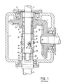
- Figs. 1 and 2 are schematic plan views of two embodiments of the mechanism according to the invention.
- the selective drive mechanism shown in fig. 1 comprises a casing 1 in which an input shaft 2, which is connected to the PTO shaft of an agricultural tractor, is rotatably mounted by a rolling bearing 3.
- the mechanism comprises two output shafts, namely a laterally oriented output shaft 4, intended for driving a harvester-chopper-loader coupled laterally to the agricultural tractor, and an output shaft 5 intended to be connected to a device equipping for example a trailer coupled to this agricultural tractor, this output shaft 5 being in the extension of the input shaft 2.
- These shafts 4 and 5 are mounted for rotation in the casing 1 by rolling bearings 6 and 7.
- a bevel gear 8 is rotatably mounted on the input shaft 2 by a needle bearing 9. This bevel gear 8 meshes with another bevel gear 10 which is wedged on the output shaft 4 driving the harvester - chopper-loader.
- the bevel gear 8 further comprises a hub 11 provided with external splines 12.
- the input shaft 2 has, towards its end, situated beyond the bevel gear 8, a part provided with external longitudinal grooves forming a slide 13 on which a sliding sleeve 14 is slidably mounted by corresponding internal grooves 15.
- the drive sleeve 14 is controlled in the usual way by a fork 16. Its positioning in one or the other of its two working positions is ensured by means of a locking ball 17 subjected to the action of a compression spring 18, mounted in the shaft 2 and capable of engaging selectively in one or the other of two housings 19 formed in the interior surface of the sliding sleeve 14.
- the end of the input shaft 2 comprises an axial journal 20 which is rotatably mounted in the hollow end forming a hub 21 of the output shaft 5 by a needle bearing 22.
- the outer surface of this hub 21 is provided with longitudinal grooves or equivalent profiling 23.
- the sliding sleeve 14 comprises, towards each end, a flange provided with longitudinal grooves 24, 25 which can be brought selectively into engagement with the grooves 12 of the hub 11 of the bevel gear 8 on the one hand or the grooves 23 of the hub 21 of the output shaft 5 on the other hand.
- the sliding sleeve 14 occupies a central position in which neither of the two output shafts is driven. If desired, a lock similar to those mentioned above can be provided for immobilizing the sliding sleeve in this middle position.
- the grooves 24 are brought into engagement with the grooves 12, so that a rotationally secured connection is established between the input shaft 2 and the bevel gear 8, and consequently between this input shaft 2 and the output shaft 4 ensuring the drive of the harvester-chopper-loader, while the output shaft 5 does not is not driven.
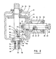
- FIG. 2 There is shown in FIG. 2 an alternative embodiment of the invention.
- the mechanism in this case comprises a casing 31 in which an input shaft 32 is journalled by a rolling bearing 33.
- This input shaft 32 is here again connected to the PTO shaft of a tractor.
- this shaft 32 passes through the casing 31 and its end 34 in the form of a hollow shaft is journalled in this casing by a rolling bearing 35.
- the shaft 32 carries a bevel gear 36 wedged on this shaft and which is engaged with another bevel gear 37 wedged on a hollow shaft 38 journalled by a rolling bearing 39 in a boss 40 of the casing 31.
- the shaft 38 is oriented perpendicular to the shaft 32. It is intended for driving the harvester-chopper-loader.
- a sliding shaft 41 which carries at its free end a control finger 42 whose role will be explained later.
- the shaft 41 has, opposite the finger 42, a part provided with longitudinal grooves 43 which joins a shaft of larger diameter 44 forming the actual output shaft of the mechanism.
- the longitudinal position of the shaft 41 in the hollow shaft 38 is determined by means of a locking ball 45 subjected to the effect of a compression spring 46, mounted in the hollow shaft 38 and capable of engaging in one or the other of the two longitudinally spaced housings 47, provided in the shaft 41.
- the hollow shaft 38 has, towards its end oriented towards the shaft 44, internal grooves 48.
- the grooves 43 are released from the grooves 48, so that in this position the hollow shaft 38, which is driven from the shaft input 32 by the bevel gear 36, 37, turns mad relative to the output shaft 44, which is free.
- the input shaft 32 ends in a part forming a hollow shaft 34.
- the second output shaft 49 of the mechanism which is intended, for example, for driving a device fitted to a trailer coupled to the harvester - chopper-loader, is here in the form of a PTO shaft, externally provided with external grooves 50 with which one can bring into engagement an articulated shaft (not shown) connected to the trailer, in a manner self classic.
- This output shaft 49 is constituted in this case by a sleeve 51 which is mounted loose on one end inner shaft 52, on which it is immobilized axially by a terminal shoulder 53 of this inner shaft and by a ring or a split ring 54.
- the inner shaft end 52 can slide in the bore of the hollow part 34 of the shaft 32 and it can be immobilized in one or the other of two positions by means of a ball 55 subjected to the action of a compression spring 56, mounted in the shaft 32, 34 and capable of engaging selectively in one or the other of two housings 57 spaced apart longitudinally from each other on the shaft end interior 52.
- the hollow shaft 34 and the sleeve 51 have on their end faces opposite teeth or dogs indicated at 58, which in the position shown in the drawing are engaged, but which are released from one another as described more far during the axial displacement of the end of the inner shaft 52 in the hollow shaft 34.
- a member 61 consisting of a lever bent at an angle, pivotally mounted around an axis 62 perpendicular to the plane containing the axes of the shafts 34 and 38.
- This lever has arms 63, 64 in the form of forks, coming to cooperate with fingers 42 and 60 ..
- the operation of the mechanism is as follows: -In the condition shown in the drawing, the teeth or dogs 58 of the hollow shaft 34 and the sleeve 51 forming the output shaft 49 are engaged, so that a kinematic connection is established between the input shaft 32 connected to the PTO shaft of the tractor and the output shaft 49 connected for example to a device fitted to a trailer coupled to the harvester-chopper-loader.
- the assembly formed by the input shaft 32, with its hollow part 34, the inner shaft end 52 and the sleeve 51 forming the output shaft 49 therefore rotates, and a drive can be provided for example by means an articulated shaft adapted by its tip on the outer grooves 50 of the sleeve 51.
- this drive is provided selectively and that any simultaneous drive is avoided, while retaining the drive possibilities of one or the other of the devices or machines coupled to the tractor.
Landscapes
- Engineering & Computer Science (AREA)
- Mechanical Engineering (AREA)
- Chemical & Material Sciences (AREA)
- Combustion & Propulsion (AREA)
- Transportation (AREA)
- Life Sciences & Earth Sciences (AREA)
- Soil Sciences (AREA)
- Environmental Sciences (AREA)
- Agricultural Machines (AREA)
- Transmission Devices (AREA)
- Arrangement And Driving Of Transmission Devices (AREA)
Priority Applications (12)
| Application Number | Priority Date | Filing Date | Title |
|---|---|---|---|
| AT81401788T ATE17982T1 (de) | 1981-11-12 | 1981-11-12 | Einrichtung zum wahlweisen antrieb von maschinen oder vorrichtungen durch die zapfwelle eines landwirtschaftlichen schleppers. |
| EP81401788A EP0081024B1 (de) | 1981-11-12 | 1981-11-12 | Einrichtung zum wahlweisen Antrieb von Maschinen oder Vorrichtungen durch die Zapfwelle eines landwirtschaftlichen Schleppers |
| DE8181401788T DE3173837D1 (en) | 1981-11-12 | 1981-11-12 | Mechanism for the selective driving of machines and devices by the power take-off shaft of an agricultural tractor |
| DE198181401788T DE81024T1 (de) | 1981-11-12 | 1981-11-12 | Einrichtung zum wahlweisen antrieb von maschinen oder vorrichtungen durch die zapfwelle eines landwirtschaftlichen schleppers. |
| US06/438,434 US4476743A (en) | 1981-11-12 | 1982-11-02 | Selective driving mechanism |
| ZA828294A ZA828294B (en) | 1981-11-12 | 1982-11-11 | Mechanism for selectively driving machines or devices from the power-take-off shaft of an agricultural tractor |
| ES517267A ES517267A0 (es) | 1981-11-12 | 1982-11-11 | Mecanismo de arrastre selectivo de maquinas o dispositivos a partir del arbol de toma de fuerza de un tractor agricola. |
| AU90419/82A AU565888B2 (en) | 1981-11-12 | 1982-11-12 | Selective driving mechanism |
| JP57198820A JPS58126223A (ja) | 1981-11-12 | 1982-11-12 | 選択駆動装置 |
| CA000415420A CA1188135A (en) | 1981-11-12 | 1982-11-12 | Selective driving mechanism |
| DK504082A DK504082A (da) | 1981-11-12 | 1982-11-12 | Mekanisme til selektiv drivning af maskiner eller apparater fra kraftudtagningsakselen paa en landbrugstraktor |
| AR291280A AR229993A1 (es) | 1981-11-12 | 1982-11-12 | Un mecanismo de accionamiento selectivo de maquinas o dispositivos desde el eje de toma de fuerza de un vehiculo |
Applications Claiming Priority (1)
| Application Number | Priority Date | Filing Date | Title |
|---|---|---|---|
| EP81401788A EP0081024B1 (de) | 1981-11-12 | 1981-11-12 | Einrichtung zum wahlweisen Antrieb von Maschinen oder Vorrichtungen durch die Zapfwelle eines landwirtschaftlichen Schleppers |
Publications (2)
| Publication Number | Publication Date |
|---|---|
| EP0081024A1 true EP0081024A1 (de) | 1983-06-15 |
| EP0081024B1 EP0081024B1 (de) | 1986-02-19 |
Family
ID=8188565
Family Applications (1)
| Application Number | Title | Priority Date | Filing Date |
|---|---|---|---|
| EP81401788A Expired EP0081024B1 (de) | 1981-11-12 | 1981-11-12 | Einrichtung zum wahlweisen Antrieb von Maschinen oder Vorrichtungen durch die Zapfwelle eines landwirtschaftlichen Schleppers |
Country Status (11)
| Country | Link |
|---|---|
| US (1) | US4476743A (de) |
| EP (1) | EP0081024B1 (de) |
| JP (1) | JPS58126223A (de) |
| AR (1) | AR229993A1 (de) |
| AT (1) | ATE17982T1 (de) |
| AU (1) | AU565888B2 (de) |
| CA (1) | CA1188135A (de) |
| DE (2) | DE81024T1 (de) |
| DK (1) | DK504082A (de) |
| ES (1) | ES517267A0 (de) |
| ZA (1) | ZA828294B (de) |
Cited By (2)
| Publication number | Priority date | Publication date | Assignee | Title |
|---|---|---|---|---|
| WO1986006690A1 (en) * | 1985-05-03 | 1986-11-20 | HARPWELD LIMITED trading as MARTIN-HARPER (ENGINEE | Power take-off apparatus |
| FR2639601A1 (fr) * | 1988-11-28 | 1990-06-01 | Castagnola Frederic | Motocyclette comportant une ou plusieurs prises de force pour accessoires de travail notamment pompe a incendie, brise-beton |
Families Citing this family (6)
| Publication number | Priority date | Publication date | Assignee | Title |
|---|---|---|---|---|
| US4592248A (en) * | 1983-12-30 | 1986-06-03 | Tci, Inc. | Quick change gear box mounting kit for ground drive implement |
| US4685861A (en) * | 1984-10-30 | 1987-08-11 | Michael Madock | Continuous shaft-driven industrial robot |
| JP3225334B2 (ja) * | 1995-06-14 | 2001-11-05 | 株式会社新川 | リードフレームの検出装置 |
| GB0020970D0 (en) * | 2000-08-25 | 2000-10-11 | Bae Systems Plc | Aircraft support vehicle |
| CN106232410B (zh) * | 2014-04-24 | 2019-07-26 | Gkn 动力传动系统北美有限公司 | 带有行星齿轮组的车辆动力传递单元(ptu) |
| EP3307953B1 (de) * | 2015-06-12 | 2019-03-06 | MTD products Inc | Schneefräse mit laufrad mit mehrfacher geschwindigkeit |
Citations (4)
| Publication number | Priority date | Publication date | Assignee | Title |
|---|---|---|---|---|
| US1583256A (en) * | 1925-06-04 | 1926-05-04 | William C Pauling | Power transmission |
| US2158483A (en) * | 1937-06-30 | 1939-05-16 | Spicer Mfg Corp | Power take-off for motor vehicles |
| US2195909A (en) * | 1938-05-16 | 1940-04-02 | Detroit Harvester Co | Power take-off assembly |
| US2630719A (en) * | 1951-05-03 | 1953-03-10 | Charles C Humbert | Transmission mechanism having selectively driven output shafts |
Family Cites Families (5)
| Publication number | Priority date | Publication date | Assignee | Title |
|---|---|---|---|---|
| US1300398A (en) * | 1918-06-14 | 1919-04-15 | Friedeman R Jaeger | Clutch. |
| US2878690A (en) * | 1956-03-16 | 1959-03-24 | Capron Michel Victor Fernand | Variable speed multibelt transmission |
| US3198301A (en) * | 1961-09-13 | 1965-08-03 | Insley Mfg Corp | Clutch and brake with resilient operator |
| US3478620A (en) * | 1967-10-06 | 1969-11-18 | Outboard Marine Corp | Marine propulsion unit with dual drive shafts and dual propeller shafts |
| US4344760A (en) * | 1979-08-15 | 1982-08-17 | Kulikowski Andrzej S | Marine propulsion system |
-
1981
- 1981-11-12 EP EP81401788A patent/EP0081024B1/de not_active Expired
- 1981-11-12 DE DE198181401788T patent/DE81024T1/de active Pending
- 1981-11-12 DE DE8181401788T patent/DE3173837D1/de not_active Expired
- 1981-11-12 AT AT81401788T patent/ATE17982T1/de active
-
1982
- 1982-11-02 US US06/438,434 patent/US4476743A/en not_active Expired - Fee Related
- 1982-11-11 ES ES517267A patent/ES517267A0/es active Granted
- 1982-11-11 ZA ZA828294A patent/ZA828294B/xx unknown
- 1982-11-12 AR AR291280A patent/AR229993A1/es active
- 1982-11-12 JP JP57198820A patent/JPS58126223A/ja active Pending
- 1982-11-12 CA CA000415420A patent/CA1188135A/en not_active Expired
- 1982-11-12 DK DK504082A patent/DK504082A/da not_active Application Discontinuation
- 1982-11-12 AU AU90419/82A patent/AU565888B2/en not_active Expired - Fee Related
Patent Citations (4)
| Publication number | Priority date | Publication date | Assignee | Title |
|---|---|---|---|---|
| US1583256A (en) * | 1925-06-04 | 1926-05-04 | William C Pauling | Power transmission |
| US2158483A (en) * | 1937-06-30 | 1939-05-16 | Spicer Mfg Corp | Power take-off for motor vehicles |
| US2195909A (en) * | 1938-05-16 | 1940-04-02 | Detroit Harvester Co | Power take-off assembly |
| US2630719A (en) * | 1951-05-03 | 1953-03-10 | Charles C Humbert | Transmission mechanism having selectively driven output shafts |
Cited By (3)
| Publication number | Priority date | Publication date | Assignee | Title |
|---|---|---|---|---|
| WO1986006690A1 (en) * | 1985-05-03 | 1986-11-20 | HARPWELD LIMITED trading as MARTIN-HARPER (ENGINEE | Power take-off apparatus |
| FR2639601A1 (fr) * | 1988-11-28 | 1990-06-01 | Castagnola Frederic | Motocyclette comportant une ou plusieurs prises de force pour accessoires de travail notamment pompe a incendie, brise-beton |
| EP0374076A1 (de) * | 1988-11-28 | 1990-06-20 | Frédéric Castagnola | Motorrad mit einer oder mehreren Zapfwellen für Zusatzeinrichtungen, wie Feuerlöschpumpen, Betonbohrer |
Also Published As
| Publication number | Publication date |
|---|---|
| ZA828294B (en) | 1984-06-27 |
| ES8400652A1 (es) | 1983-11-01 |
| US4476743A (en) | 1984-10-16 |
| JPS58126223A (ja) | 1983-07-27 |
| DK504082A (da) | 1983-05-13 |
| EP0081024B1 (de) | 1986-02-19 |
| CA1188135A (en) | 1985-06-04 |
| DE81024T1 (de) | 1983-10-27 |
| ES517267A0 (es) | 1983-11-01 |
| DE3173837D1 (en) | 1986-03-27 |
| ATE17982T1 (de) | 1986-03-15 |
| AU9041982A (en) | 1983-05-19 |
| AR229993A1 (es) | 1984-02-29 |
| AU565888B2 (en) | 1987-10-01 |
Similar Documents
| Publication | Publication Date | Title |
|---|---|---|
| FR2462620A1 (fr) | Differentiel pour vehicule a moteur | |
| EP1347207B1 (de) | Linearantrieb mit Gewinderollen | |
| FR2541225A1 (fr) | Derailleur pour une bicyclette | |
| EP4185500B1 (de) | Getriebe und mit einem solchen getriebe ausgestattetes kraftfahrzeug | |
| EP0081024A1 (de) | Einrichtung zum wahlweisen Antrieb von Maschinen oder Vorrichtungen durch die Zapfwelle eines landwirtschaftlichen Schleppers | |
| EP1359345A2 (de) | Antriebsvorrichtung mit Wälzlager | |
| EP0488857B1 (de) | Interne Steuervorrichtung für Schaltgetriebe | |
| EP0943759B2 (de) | Anordnung für die Bewegungsübertragung zwischen einem Riegel und einem Kraftfahrzeugschloss | |
| EP0384838B1 (de) | Einrichtung zur Steuerung der Neigung eines Scheinwerfers | |
| EP0560645B1 (de) | Gangschalthebelvorrichtung, insbesondere für Kraftfahrzeuge | |
| EP0019501B1 (de) | Vorrichtung zum Steuern eines Aussenrückspiegels vom Innern eines Fahrzeuges | |
| FR2709798A1 (fr) | Boîte de vitesse à embrayage incorporé. | |
| FR2566342A1 (fr) | Dispositif pour la commande manuelle de la boite de vitesses d'un vehicule automobile | |
| EP0571274A1 (de) | Feststellbrems-Steuervorrichtung | |
| FR2696803A1 (fr) | Dispositif de détection de l'enclenchement de vitesses d'une boîte de vitesses. | |
| EP0710786B1 (de) | Schaltgetriebe | |
| FR2599454A1 (fr) | Transmission a engrenages planetaires notamment pour robot industriel | |
| EP0007861B1 (de) | Verstellvorrichtung für einen Rückblickspiegel, insbesondere für Fahrzeuge | |
| FR2564058A1 (fr) | Systeme de transmission principal, pour un helicoptere | |
| FR2676843A1 (fr) | Dispositif de commande manuelle pour une commande a distance par cables flexibles, notamment pour la commande de changement de vitesse d'une boite de vitesses. | |
| EP0084472A1 (de) | Verstelleinrichtung für Schaltgetriebe | |
| EP0283389B1 (de) | Bedienungseinrichtung eines Differentials mit hydraulisch geregeltem Schlupf und ein damit ausgestattetes Fahrzeug | |
| FR2833674A1 (fr) | Dispositif de transmission entre un arbre primaire moteur et un arbre de sortie | |
| FR2745348A3 (fr) | Dispositif d'embrayage ameliore, destine a l'embrayage et au debrayage de deux arbres | |
| EP0753431A1 (de) | Vorrichtung zum Aufbewahren von Gegenständen, insbesondere in Kraftfahrzeugen |
Legal Events
| Date | Code | Title | Description |
|---|---|---|---|
| PUAI | Public reference made under article 153(3) epc to a published international application that has entered the european phase |
Free format text: ORIGINAL CODE: 0009012 |
|
| AK | Designated contracting states |
Designated state(s): AT BE CH DE FR GB LI NL |
|
| RBV | Designated contracting states (corrected) |
Designated state(s): AT BE CH DE FR GB LI NL |
|
| TCAT | At: translation of patent claims filed | ||
| TCNL | Nl: translation of patent claims filed | ||
| DET | De: translation of patent claims | ||
| 17P | Request for examination filed |
Effective date: 19831024 |
|
| GRAA | (expected) grant |
Free format text: ORIGINAL CODE: 0009210 |
|
| AK | Designated contracting states |
Designated state(s): AT BE CH DE FR GB LI NL |
|
| REF | Corresponds to: |
Ref document number: 17982 Country of ref document: AT Date of ref document: 19860315 Kind code of ref document: T |
|
| REF | Corresponds to: |
Ref document number: 3173837 Country of ref document: DE Date of ref document: 19860327 |
|
| PGFP | Annual fee paid to national office [announced via postgrant information from national office to epo] |
Ref country code: AT Payment date: 19861110 Year of fee payment: 6 |
|
| PGFP | Annual fee paid to national office [announced via postgrant information from national office to epo] |
Ref country code: NL Payment date: 19861130 Year of fee payment: 6 |
|
| PLBE | No opposition filed within time limit |
Free format text: ORIGINAL CODE: 0009261 |
|
| STAA | Information on the status of an ep patent application or granted ep patent |
Free format text: STATUS: NO OPPOSITION FILED WITHIN TIME LIMIT |
|
| 26N | No opposition filed | ||
| PG25 | Lapsed in a contracting state [announced via postgrant information from national office to epo] |
Ref country code: AT Effective date: 19871112 |
|
| PG25 | Lapsed in a contracting state [announced via postgrant information from national office to epo] |
Ref country code: LI Effective date: 19871130 Ref country code: CH Effective date: 19871130 Ref country code: BE Effective date: 19871130 |
|
| BERE | Be: lapsed |
Owner name: DEERE & CY Effective date: 19871130 |
|
| PG25 | Lapsed in a contracting state [announced via postgrant information from national office to epo] |
Ref country code: NL Effective date: 19880601 |
|
| NLV4 | Nl: lapsed or anulled due to non-payment of the annual fee | ||
| GBPC | Gb: european patent ceased through non-payment of renewal fee | ||
| PG25 | Lapsed in a contracting state [announced via postgrant information from national office to epo] |
Ref country code: FR Free format text: LAPSE BECAUSE OF NON-PAYMENT OF DUE FEES Effective date: 19880729 |
|
| REG | Reference to a national code |
Ref country code: CH Ref legal event code: PL |
|
| PG25 | Lapsed in a contracting state [announced via postgrant information from national office to epo] |
Ref country code: DE Effective date: 19880802 |
|
| REG | Reference to a national code |
Ref country code: FR Ref legal event code: ST |
|
| PG25 | Lapsed in a contracting state [announced via postgrant information from national office to epo] |
Ref country code: GB Effective date: 19881122 |