EP0080927B1 - Empfänger für eine Sonde zum Detektieren und Messen von Phänomenen der Erdumgebung - Google Patents
Empfänger für eine Sonde zum Detektieren und Messen von Phänomenen der Erdumgebung Download PDFInfo
- Publication number
- EP0080927B1 EP0080927B1 EP82402122A EP82402122A EP0080927B1 EP 0080927 B1 EP0080927 B1 EP 0080927B1 EP 82402122 A EP82402122 A EP 82402122A EP 82402122 A EP82402122 A EP 82402122A EP 0080927 B1 EP0080927 B1 EP 0080927B1
- Authority
- EP
- European Patent Office
- Prior art keywords
- signals
- frequency
- stage
- input
- receiver
- Prior art date
- Legal status (The legal status is an assumption and is not a legal conclusion. Google has not performed a legal analysis and makes no representation as to the accuracy of the status listed.)
- Expired
Links
Images
Classifications
-
- G—PHYSICS
- G01—MEASURING; TESTING
- G01S—RADIO DIRECTION-FINDING; RADIO NAVIGATION; DETERMINING DISTANCE OR VELOCITY BY USE OF RADIO WAVES; LOCATING OR PRESENCE-DETECTING BY USE OF THE REFLECTION OR RERADIATION OF RADIO WAVES; ANALOGOUS ARRANGEMENTS USING OTHER WAVES
- G01S13/00—Systems using the reflection or reradiation of radio waves, e.g. radar systems; Analogous systems using reflection or reradiation of waves whose nature or wavelength is irrelevant or unspecified
- G01S13/88—Radar or analogous systems specially adapted for specific applications
- G01S13/95—Radar or analogous systems specially adapted for specific applications for meteorological use
- G01S13/951—Radar or analogous systems specially adapted for specific applications for meteorological use ground based
-
- G—PHYSICS
- G01—MEASURING; TESTING
- G01S—RADIO DIRECTION-FINDING; RADIO NAVIGATION; DETERMINING DISTANCE OR VELOCITY BY USE OF RADIO WAVES; LOCATING OR PRESENCE-DETECTING BY USE OF THE REFLECTION OR RERADIATION OF RADIO WAVES; ANALOGOUS ARRANGEMENTS USING OTHER WAVES
- G01S7/00—Details of systems according to groups G01S13/00, G01S15/00, G01S17/00
- G01S7/02—Details of systems according to groups G01S13/00, G01S15/00, G01S17/00 of systems according to group G01S13/00
- G01S7/35—Details of non-pulse systems
- G01S7/352—Receivers
-
- G—PHYSICS
- G01—MEASURING; TESTING
- G01V—GEOPHYSICS; GRAVITATIONAL MEASUREMENTS; DETECTING MASSES OR OBJECTS; TAGS
- G01V3/00—Electric or magnetic prospecting or detecting; Measuring magnetic field characteristics of the earth, e.g. declination, deviation
- G01V3/12—Electric or magnetic prospecting or detecting; Measuring magnetic field characteristics of the earth, e.g. declination, deviation operating with electromagnetic waves
-
- Y—GENERAL TAGGING OF NEW TECHNOLOGICAL DEVELOPMENTS; GENERAL TAGGING OF CROSS-SECTIONAL TECHNOLOGIES SPANNING OVER SEVERAL SECTIONS OF THE IPC; TECHNICAL SUBJECTS COVERED BY FORMER USPC CROSS-REFERENCE ART COLLECTIONS [XRACs] AND DIGESTS
- Y02—TECHNOLOGIES OR APPLICATIONS FOR MITIGATION OR ADAPTATION AGAINST CLIMATE CHANGE
- Y02A—TECHNOLOGIES FOR ADAPTATION TO CLIMATE CHANGE
- Y02A90/00—Technologies having an indirect contribution to adaptation to climate change
- Y02A90/10—Information and communication technologies [ICT] supporting adaptation to climate change, e.g. for weather forecasting or climate simulation
Definitions
- the present invention relates to a receiver for a sounder allowing the detection and the measurement of phenomena relating to the environment of the terrestrial globe.
- This receiver is applicable to sounders allowing the study of phenomena relating to the environment of the terrestrial globe and in particular to all sounders intended for the study of the ionosphere and in particular for the study of short-term modifications and small amplitude of the gradient of the electron density of the ionosphere.
- This receiver can also be applied to sounders allowing the study of other phenomena such as for example, the study or the monitoring of sea swell.
- the ionosphere is the area above 70 km altitude in which, under the influence of solar radiation, a fraction of the atoms and molecules that make up the Earth's atmosphere, is separated into positive ions and into negative electrons.
- the rarity of the atmosphere is such that the density of electrons is low.
- the atmosphere is much denser.
- the energy of the solar radiation has been consumed at high altitude for the ionization of molecules, and the residual energy of this radiation is no longer enough to produce significant ionization.
- the ionosphere is a protective shield of the Earth's surface against ultraviolet certain dan - gerous.
- the most important ionization occurs at an altitude of about 200 km and attracts a few hundred thousand electrons per cubic centimeter (10 5 to 10'lcm ').
- the most characteristic quantity of the ionosphere is therefore the electron density or ionization density. Knowing this density at different altitudes makes it possible to detect the disturbances which the ionosphere undergoes as a result of events which the earth undergoes (earthquakes for example).
- Knowledge of the electron density of the ionosphere also makes it possible to study the sudden ionospheric disturbances produced by the bursts of solar activity; these disturbances are reflected in fact by a sudden increase in the electromagnetic radiation emitted towards the earth, in particular in the range of X-rays.
- This sounder includes a channel for transmitting electromagnetic signals towards the ionosphere, and a receiver making it possible to capture the echoes of these signals on different layers of the ionosphere.
- the electromagnetic waves emitted are generally waves modulated by pulses. These pulses are emitted in the direction of the ionosphere or of the phenomenon to be detected and the resulting echoes are picked up by the receiver which detects these echoes according to their amplitude, their frequency and their frequency shift.
- an ionospheric layer only reflects electromagnetic waves whose frequency is lower than the critical frequency linked to the maximum electronic density of this layer.
- the waves emitted at a predetermined frequency and lower than the critical frequency provide echoes at a known instant with respect to the emission instant, making it possible to locate the altitude of the ionospheric region whose electronic density is that necessary for the reflection of the electromagnetic sounding wave.
- the sounder described in the aforementioned patent application also makes it possible to detect small variations in electronic density thanks to the use of the Doppler radar technique. .
- Such variations in the electron density of the ionosphere as a function of time result in frequency shifts relative to the frequency of sounding of the echoes resulting from the waves emitted in the direction of the ionosphere. This effect is called the Doppler effect.
- the sounder can make it possible to observe frequency shifts of very low values, corresponding to variations in the phase path of the electromagnetic sound waves of the order, of the order of one meter per second; in addition, this sounder has a good spatial resolution determined by very small widths of the pulses emitted towards the ionosphere.
- the object of the invention is to remedy these drawbacks and in particular to produce a receiver for a sounder allowing the detection and the measurement of phenomena relating to the environment of the terrestrial globe, this receiver making it possible to carry out measurements of Doppler frequencies and of group propagation time, without these being disturbed by the distortions generated by the receiver or by interference at its input. According to the invention, these objects are achieved with a receiver as defined in claim 1.
- the frequency transposition means of each of the second and third stages comprise a mixer making it possible to mix the signals received on an input with reference frequency signals coming from an oscillator, the oscillators of the second and third stages being slaved in phase and providing signals having different reference frequencies.
- the filtering means are quartz filters with constant group propagation time.
- the attenuation means of the first stage are adjustable by switching voltages, each voltage being independently adjustable for each frequency of reception of the echo signals.
- the attenuation means of the second stage are adjustable by automatic gain control.
- the phase-controlled oscillators are frequency synthesizers respectively providing on their outputs, signals having said reference frequencies, these synthesizers being connected to a high stability pilot oscillator.
- the receiver further comprises a coaxial relay for connecting an output of the test and calibration channel to the input of the reception channel.
- the receiver further comprises a fourth stage comprising in series, frequency transposition, filtering and amplification means receiving signals from the third stage, the frequency transposition means comprising a mixer receiving the signals from the third stage and an oscillator applying signals having another reference frequency to another input of this mixer, these reference frequency signals being supplied by another output of a frequency synthesizer connected to the pilot oscillator.
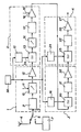
- This receiver comprises a reception channel consisting of several stages 1, 2, 3, 4 which will be described later in detail.
- An input 5 of this reception channel receives via an antenna 6 impulse signals echoed from the electromagnetic impulse signals emitted towards a phenomenon relating to the earth block.
- This receiver also includes an amplitude and frequency offset test and calibration channel for electromagnetic signals.
- This test channel is essentially constituted by a simulator 7 which first of all makes it possible to check the operation of the reception channel in injec both in the latter, by means of a coaxial relay 8, reference signals having a predetermined amplitude and frequency. It also allows the reception channel to be calibrated.
- the simulator 7 therefore supplies signals of predetermined frequency and amplitude and also supplies signals shifted in frequency.
- the reception channel comprises a first stage 1 which includes means for filtering, attenuating and amplifying the echo signals received.
- the filtering means are constituted by a bandpass filter 9, while the attenuation means are constituted by an attenuator 10 programmable for voltages which are applied to it and which depend respectively on the reception levels of the predetermined frequencies of the signal signals. input (or useful signals).
- the voltage control input of this attenuator is shown at 11.
- This attenuator allows, when the input of the receiver receives parasitic signals, or when the distortion generated by the receiver is large enough, to minimize the amplitude of this distortion or of these spurious signals with respect to the amplitude of the useful signals received.
- the amplification means of this first stage are constituted by an amplifier 12.
- the reception channel also comprises a second stage 2, constituted by means of frequency transposition, attenuation, filtering and amplification.
- the frequency transposition means are constituted by a mixer 13 which makes it possible to mix the signals supplied by the amplifier 12 of predetermined frequency, with signals having a reference frequency, applied to an input 14 of the mixer, by an output of a local oscillator 15, which will be described later in detail.
- the attenuation means are constituted by an attenuator 16 with automatic gain control which receives the output signals from the mixer 13 and which makes it possible to adjust the level of the spurious signals on the reception channel.
- the adjustment of this attenuator consists in first choosing a large attenuation rate, then in decreasing this rate gradually up to a certain threshold so that when the input of the receiver receives echo signals, the amplitude of these signals is greater than this threshold.
- the filtering means of this second stage consist of a Bessel filter 17 with quartz.
- This filter is followed by amplification means constituted in a known manner by an amplifier 18 with automatic gain control 19.
- the third stage of the reception channel comprises means for frequency transposition, filtering and amplification.
- the frequency transposition means consist of a mixer 20 which receives the output signals from the amplifier 18 and signals having a predetermined frequency and which are supplied by a local oscillator 16, which will be described later in detail.
- the output of this mixer is connected to the input of the filtering means constituted by a Bessel filter 21, with quartz.
- the output of this filter is connected to the amplification means, constituted by an amplifier 22.
- the reception channel comprises a fourth stage comprising the means of frequency transposition, filtering and amplification.
- the frequency transposition means are constituted by a mixer 23 which receives the output signals from the amplifier 22 as well as reference frequency signals supplied by a local oscillator 24.
- the output of the mixer 23 is connected to the filtering means constituted by a Bessel 25 filter, quartz.
- the output of this filter 25 is connected to amplification means constituted by an amplifier 26.
- the output 27 of this amplifier constitutes the output of the reception channel.
- the oscillators 15, 16 and 24 of the second, third and fourth stages of the reception channel are constituted by frequency synthesizers controlled by a quartz oscillator 28 and supplying signals of different reference frequencies; these oscillators are therefore phase locked.
- the filters 17, 21 and 25 used are Bessel filters with phaselinear, intended to transmit received signals, without rebound.
- Filters 9, 17, 21 are bandpass type filters.
- the filter 9 of the first stage 1 of the reception channel is a filter whose bandwidth is between 0.5 and 30 MHz, taking into account the fact that the predetermined frequencies of the input signals are located in this frequency band .
- the attenuation of this filter is 0.1 dB (decibel).
- This filter is in fact intended to eliminate the image frequency from the frequency of the useful input signal from the receiver.
- the input signals from the receiver can have several predetermined frequencies which of course depend on the predetermined emission frequencies.
- the attenuator 10 which is connected to the filter 9 of the first stage has, as indicated above, an attenuation rate which can be adjusted automatically by voltages which depend on the reception levels of the predetermined frequencies of the signals received at the entrance to the reception lane. In fact, this attenuator is made necessary, because the amplitude of the signals received varies according to the predetermined frequencies of these signals. This attenuator can also be controlled at the rate of changes in the predetermined frequencies of the input signals. This attenuator has a coefficient of attenu variable between 1.5 and 30 dB.
- the amplifier 12 which is connected to the output of the attenuator 10, is a broadband amplifier which has a gain close to 30 dB, but which also has a very large operating dynamic since it remains linear up to a level close to 13 dBm (13 dB above 1 milliwatt) at output.
- the mixer 13 operates up to a level of 13 dBm on its input and it transposes the reception frequency F e to 40 MHz, by mixing with the signals delivered by the oscillator 15, whose frequency is equal to F e +40 MHz.
- the frequency of the signals is equal to 40 MHz ⁇ F d (F d being the frequency offset between the signals transmitted towards a phenomenon and the signals received at the input of the reception channel).
- the mixer 13 has an attenuation coefficient close to 5 db.
- the second stage is a medium frequency stage and it operates at frequencies close to 40 MHz.
- the filter 17 is a quartz Bessel filter, of the bandpass type, whose bandwidth varies between -86 KHz and +86 KHz, around a central frequency of 40 MHz. This filter has an attenuation coefficient close to 4 dB and a linear phase response.
- the amplifier 18 with automatic gain control is an amplifier tuned to a frequency of 40 MHz, its gain can vary between 30 dB and 76 dB. This gain can be adjusted in a known manner by a control voltage applied to the input 19.
- the mixer 20 makes it possible to mix the signals received from the amplifier 18 with signals produced by the local oscillator 16, the frequency of which is equal at 50 MHz. As a result, at the output of the mixer 20, the signals have an average frequency of 10 MHz around which the offset frequencies vary. This mixer has an attenuation close to 5 dB.
- the filter 21 which is connected to the mixer 20 defines the final passband of the reception channel. This filter is a bandpass filter whose central frequency is close to 10 MHz and whose bandwidth can vary from 2 to 60 KHz.
- the amplifier 22 which is connected to the filter 21 is also a linear amplifier, tuned to the frequency of 10 MHz.
- the signals of this oscillator have a reference frequency of 9.9 MHz; it follows that the output signal from this mixer is a signal whose frequency varies as a function of the offset frequencies of the input signals, around 100 KHz.
- This mixer has an attenuation coefficient close to 7.5 dB.
- the filter 25 which is connected to the output of this mixer is a low-pass filter whose cut-off frequency is equal to 200 KHz.
- This filter 25 is a Bessel filter.
- the output of this filter is connected to a linear amplifier whose gain is close to 20 dB.
- the output 27 of this amplifier provides the signals which will make it possible to carry out the frequency offset measurements of the input signals and, thus, will make it possible to interpret certain parameters of the phenomena studied. These signals have a frequency close to 100 KHz for an amplitude close to 3 effective volts.
- the phase control of the various local oscillators 11, 16 and 24 is essential since the reception frequencies of the input signals can vary from 0.5 to 30 MHz and we want to analyze frequency shifts close to 1 / 10 Hz especially in the study of the ionosphere.
- This phase control is achieved by direct synthesis, using frequency synthesizers controlled by a quartz oscillator 28. This eliminates the risk of errors in the frequency offset measurements. This result is important since in known receivers, the local oscillators are not phase locked relative to one another. In the receiver which has just been described, this control makes it possible to obtain a very high spectral purity and a very low residual phase noise. This receiver must be able to be tuned very quickly to the reception frequency and this tuning is done using the first local oscillator 15, around 40 MHz.
Landscapes
- Engineering & Computer Science (AREA)
- Remote Sensing (AREA)
- Physics & Mathematics (AREA)
- Radar, Positioning & Navigation (AREA)
- General Physics & Mathematics (AREA)
- Electromagnetism (AREA)
- Computer Networks & Wireless Communication (AREA)
- Life Sciences & Earth Sciences (AREA)
- Environmental & Geological Engineering (AREA)
- Geology (AREA)
- General Life Sciences & Earth Sciences (AREA)
- Geophysics (AREA)
- Superheterodyne Receivers (AREA)
- Measurement Of Velocity Or Position Using Acoustic Or Ultrasonic Waves (AREA)
Claims (9)
Applications Claiming Priority (2)
| Application Number | Priority Date | Filing Date | Title |
|---|---|---|---|
| FR8121969A FR2517071A1 (fr) | 1981-11-24 | 1981-11-24 | Recepteur pour sondeur de detection et de mesure de phenomenes relatifs a l'environnement du globe terrestre |
| FR8121969 | 1981-11-24 |
Publications (3)
| Publication Number | Publication Date |
|---|---|
| EP0080927A2 EP0080927A2 (de) | 1983-06-08 |
| EP0080927A3 EP0080927A3 (en) | 1983-07-06 |
| EP0080927B1 true EP0080927B1 (de) | 1987-03-18 |
Family
ID=9264305
Family Applications (1)
| Application Number | Title | Priority Date | Filing Date |
|---|---|---|---|
| EP82402122A Expired EP0080927B1 (de) | 1981-11-24 | 1982-11-22 | Empfänger für eine Sonde zum Detektieren und Messen von Phänomenen der Erdumgebung |
Country Status (4)
| Country | Link |
|---|---|
| US (1) | US4554546A (de) |
| EP (1) | EP0080927B1 (de) |
| DE (1) | DE3275756D1 (de) |
| FR (1) | FR2517071A1 (de) |
Families Citing this family (13)
| Publication number | Priority date | Publication date | Assignee | Title |
|---|---|---|---|---|
| IL96129A0 (en) * | 1990-07-20 | 1991-07-18 | Spectronix Ltd | Method and apparatus for detecting a fire,explosion,or projectile-penetration in a monitored space |
| US5445946A (en) * | 1993-04-13 | 1995-08-29 | Molecular Probes, Inc. | Intravacuolar stains for yeast and other fungi |
| RU2159450C2 (ru) * | 1995-04-07 | 2000-11-20 | Кусида Есио | Способ и устройство для определения диастрофизма |
| JP3504495B2 (ja) | 1998-04-28 | 2004-03-08 | 松下電器産業株式会社 | アレーアンテナ無線通信装置 |
| GB2365239A (en) * | 2000-07-26 | 2002-02-13 | Alenia Marconi Systems Ltd | Near-vertical incidence skywave HF radar |
| US7776529B2 (en) | 2003-12-05 | 2010-08-17 | Life Technologies Corporation | Methine-substituted cyanine dye compounds |
| EP1885718B1 (de) | 2005-05-11 | 2017-03-15 | Life Technologies Corporation | Chemische fluoreszente verbindungen mit hoher selektivität für doppelstrang-dna sowie verfahren zu ihrer verwendung |
| US20080191580A1 (en) * | 2007-02-14 | 2008-08-14 | Harold Stanley Deyo | Harmonic Energy Exchange Device |
| US8325084B2 (en) * | 2007-03-13 | 2012-12-04 | Baron Services, Inc. | System for calibration of dual polarization radar with built-in test couplers |
| US7554486B2 (en) * | 2007-03-13 | 2009-06-30 | Baron Services, Inc. | System and method for dual polarization radar with automatic built-in test equipment and calibration |
| US7592948B2 (en) * | 2007-03-13 | 2009-09-22 | Baron Services, Inc. | System and method for dual polarization radar with automatic built-in test equipment and calibration |
| GB0711531D0 (en) * | 2007-06-15 | 2007-07-25 | Qinetiq Ltd | Radar coordinate registration |
| US11047967B2 (en) * | 2018-07-12 | 2021-06-29 | Southwest Research Institute | Removal of directwave high frequency signal for ionospheric sounder return processing |
Citations (1)
| Publication number | Priority date | Publication date | Assignee | Title |
|---|---|---|---|---|
| FR2461264A1 (fr) * | 1979-07-06 | 1981-01-30 | Commissariat Energie Atomique | Sondeur pour la detection et la mesure de phenomenes relatifs a l'environnement du globe terrestre |
Family Cites Families (10)
| Publication number | Priority date | Publication date | Assignee | Title |
|---|---|---|---|---|
| US4206510A (en) * | 1955-06-27 | 1980-06-03 | The United States Of America As Represented By The Secretary Of The Navy | Automatic detection and classification device |
| US3078460A (en) * | 1958-09-02 | 1963-02-19 | Cubic Corp | Electronic surveying system |
| US3063034A (en) * | 1958-10-20 | 1962-11-06 | Texaco Inc | Method and apparatus for data processing |
| US2995748A (en) * | 1959-02-04 | 1961-08-08 | Benjamin R Cole | Reliability check circuits |
| US3158818A (en) * | 1962-07-31 | 1964-11-24 | David J Plumpe | Automatic gain control signal translating system |
| GB1272223A (en) * | 1968-10-04 | 1972-04-26 | Plessey Co Ltd | Improvements in or relating to microwave radar equipment |
| US4041490A (en) * | 1976-06-25 | 1977-08-09 | Cubic Corporation | Measurement system calibrated to be insensitive to temperature variation induced changes in internal phase shifts present in the system |
| US4138645A (en) * | 1977-05-31 | 1979-02-06 | Cutler-Hammer, Inc. | Wideband signal calibration system |
| SU809019A1 (ru) * | 1978-06-19 | 1981-02-28 | Казанский Ордена Трудового Красногознамени Государственный Универси-Tet Им. B.И.Ульянова-Ленина | Способ измерени концентрацииэлЕКТРОНОВ B иОНОСфЕРЕ |
| FR2462720A1 (fr) * | 1979-07-31 | 1981-02-13 | Rech Geolog Miniere | Dispositif emetteur recepteur multifrequenciel pour appareil de prospection electromagnetique |
-
1981
- 1981-11-24 FR FR8121969A patent/FR2517071A1/fr active Granted
-
1982
- 1982-11-18 US US06/442,581 patent/US4554546A/en not_active Expired - Fee Related
- 1982-11-22 DE DE8282402122T patent/DE3275756D1/de not_active Expired
- 1982-11-22 EP EP82402122A patent/EP0080927B1/de not_active Expired
Patent Citations (1)
| Publication number | Priority date | Publication date | Assignee | Title |
|---|---|---|---|---|
| FR2461264A1 (fr) * | 1979-07-06 | 1981-01-30 | Commissariat Energie Atomique | Sondeur pour la detection et la mesure de phenomenes relatifs a l'environnement du globe terrestre |
Non-Patent Citations (1)
| Title |
|---|
| IEEE TRANSACTIONS ON MICROWAVE THEORY AND TECHNIQUES, vol. MTT-27, no. 3, mars 1979, pages 245-248, New York (USA); H.-I. CONG et al.: "The low-noise 115-GHz receiver on the Columbia-GISS 4-ft radio telescope". * |
Also Published As
| Publication number | Publication date |
|---|---|
| FR2517071A1 (fr) | 1983-05-27 |
| FR2517071B1 (de) | 1984-01-06 |
| DE3275756D1 (en) | 1987-04-23 |
| EP0080927A2 (de) | 1983-06-08 |
| EP0080927A3 (en) | 1983-07-06 |
| US4554546A (en) | 1985-11-19 |
Similar Documents
| Publication | Publication Date | Title |
|---|---|---|
| EP0080927B1 (de) | Empfänger für eine Sonde zum Detektieren und Messen von Phänomenen der Erdumgebung | |
| EP0258917B1 (de) | Frequenzmoduliertes Dauerstrichradar zur Entfernungsmessung | |
| CA2318455C (fr) | Technique pour l'estimation de pluie a partir d'un radar meteorologique a diversite de polarisation | |
| EP0496329B1 (de) | Im Satellit eingebautes Seestreustrahlungsmessgerät | |
| EP2535733B1 (de) | Kompaktsystem zur Hochdruck-Höhenmessung | |
| EP0170557B1 (de) | Frequenzmodulierter Radiohöhenmesser | |
| US6366857B1 (en) | Noise estimator for seismic exploration | |
| Masson | Atmospheric effects and calibrations | |
| FR2751754A1 (fr) | Altimetre radar a emission continue | |
| EP1403962B1 (de) | Verfahren und Vorrichtung zur Kalibrierung-Entzerrung eines Empfangssystems | |
| WO2019243164A1 (fr) | Procede de mesure de la hauteur de vagues a l'aide d'un radar aeroporte | |
| EP2706676B1 (de) | Verfahren zur Kennzeichnung einer Übertragungsantenne eines Satelliten auf seiner Umlaufsbahn und Anordnung dafür. | |
| EP0022410B1 (de) | Sondiergerät zum Bestimmen und Messen relativer Phänomene in der Umgebung des Erdballs | |
| CA2330346A1 (fr) | Methode d'etalonnage d'un radioaltimetre de type fm/cw et radioaltimetre concu pour la mise en oeuvre de cette methode | |
| EP0073162B1 (de) | Verfahren zum Schützen eines Radars von Störsendungen und Radargerät zum Ausführen dieses Verfahrens | |
| EP3384311B1 (de) | Kalibrationsverfahren einer elektronisch abtastenden sektorantenne und zugehörige messvorrichtung | |
| FR2745388A1 (fr) | Procede de mesure, de type altimetrique, destine a etre mis en oeuvre a bord d'un satellite | |
| WO2006027427A1 (fr) | Dispositif d'amplification du signal d'une antenne de reception | |
| Subramanian et al. | A new investigation of microbursts at meter-decameter wavelengths | |
| EP0016674B1 (de) | Frequenzdiskriminator und damit stabilisierter Oszillator | |
| Moore et al. | Radar and Oceanography | |
| EP0097565A1 (de) | Generator mit festen und/oder verschiebbarer Impulsen mit einer beliebig grossen und in Stufen steuerbaren Verzögerung | |
| WO2023174774A1 (fr) | Système radar et procédé associé pour optimiser l'élimination de fouillis radar | |
| Herzig et al. | Pre-launch calibration of the SeaWinds scatterometer electronics subsystem | |
| FR2641916A1 (en) | Frequency-modulated transmitter/receiver |
Legal Events
| Date | Code | Title | Description |
|---|---|---|---|
| PUAI | Public reference made under article 153(3) epc to a published international application that has entered the european phase |
Free format text: ORIGINAL CODE: 0009012 |
|
| PUAL | Search report despatched |
Free format text: ORIGINAL CODE: 0009013 |
|
| AK | Designated contracting states |
Designated state(s): BE DE GB IT NL |
|
| AK | Designated contracting states |
Designated state(s): BE DE GB IT NL |
|
| 17P | Request for examination filed |
Effective date: 19831205 |
|
| GRAA | (expected) grant |
Free format text: ORIGINAL CODE: 0009210 |
|
| AK | Designated contracting states |
Kind code of ref document: B1 Designated state(s): BE DE GB IT NL |
|
| REF | Corresponds to: |
Ref document number: 3275756 Country of ref document: DE Date of ref document: 19870423 |
|
| ITF | It: translation for a ep patent filed |
Owner name: JACOBACCI & PERANI S.P.A. |
|
| PGFP | Annual fee paid to national office [announced via postgrant information from national office to epo] |
Ref country code: NL Payment date: 19871130 Year of fee payment: 6 |
|
| BECN | Be: change of holder's name |
Effective date: 19870318 |
|
| RAP2 | Party data changed (patent owner data changed or rights of a patent transferred) |
Owner name: COMMISSARIAT A L'ENERGIE ATOMIQUE |
|
| PLBE | No opposition filed within time limit |
Free format text: ORIGINAL CODE: 0009261 |
|
| STAA | Information on the status of an ep patent application or granted ep patent |
Free format text: STATUS: NO OPPOSITION FILED WITHIN TIME LIMIT |
|
| 26N | No opposition filed | ||
| NLT2 | Nl: modifications (of names), taken from the european patent patent bulletin |
Owner name: COMMISSARIAT A L'ENERGIE ATOMIQUE TE PARIJS, FRANK |
|
| PG25 | Lapsed in a contracting state [announced via postgrant information from national office to epo] |
Ref country code: GB Effective date: 19891122 |
|
| PG25 | Lapsed in a contracting state [announced via postgrant information from national office to epo] |
Ref country code: BE Effective date: 19891130 |
|
| BERE | Be: lapsed |
Owner name: COMMISSARIAT A L'ENERGIE ATOMIQUE Effective date: 19891130 |
|
| PG25 | Lapsed in a contracting state [announced via postgrant information from national office to epo] |
Ref country code: NL Effective date: 19900601 |
|
| NLV4 | Nl: lapsed or anulled due to non-payment of the annual fee | ||
| GBPC | Gb: european patent ceased through non-payment of renewal fee | ||
| PG25 | Lapsed in a contracting state [announced via postgrant information from national office to epo] |
Ref country code: DE Effective date: 19900801 |