EP0097565A1 - Generator mit festen und/oder verschiebbarer Impulsen mit einer beliebig grossen und in Stufen steuerbaren Verzögerung - Google Patents
Generator mit festen und/oder verschiebbarer Impulsen mit einer beliebig grossen und in Stufen steuerbaren Verzögerung Download PDFInfo
- Publication number
- EP0097565A1 EP0097565A1 EP83401157A EP83401157A EP0097565A1 EP 0097565 A1 EP0097565 A1 EP 0097565A1 EP 83401157 A EP83401157 A EP 83401157A EP 83401157 A EP83401157 A EP 83401157A EP 0097565 A1 EP0097565 A1 EP 0097565A1
- Authority
- EP
- European Patent Office
- Prior art keywords
- fixed
- pulse
- pulses
- generator
- generator according
- Prior art date
- Legal status (The legal status is an assumption and is not a legal conclusion. Google has not performed a legal analysis and makes no representation as to the accuracy of the status listed.)
- Withdrawn
Links
Images


Classifications
-
- G—PHYSICS
- G01—MEASURING; TESTING
- G01S—RADIO DIRECTION-FINDING; RADIO NAVIGATION; DETERMINING DISTANCE OR VELOCITY BY USE OF RADIO WAVES; LOCATING OR PRESENCE-DETECTING BY USE OF THE REFLECTION OR RERADIATION OF RADIO WAVES; ANALOGOUS ARRANGEMENTS USING OTHER WAVES
- G01S13/00—Systems using the reflection or reradiation of radio waves, e.g. radar systems; Analogous systems using reflection or reradiation of waves whose nature or wavelength is irrelevant or unspecified
- G01S13/02—Systems using reflection of radio waves, e.g. primary radar systems; Analogous systems
- G01S13/06—Systems determining position data of a target
- G01S13/08—Systems for measuring distance only
- G01S13/10—Systems for measuring distance only using transmission of interrupted, pulse modulated waves
- G01S13/22—Systems for measuring distance only using transmission of interrupted, pulse modulated waves using irregular pulse repetition frequency
- G01S13/225—Systems for measuring distance only using transmission of interrupted, pulse modulated waves using irregular pulse repetition frequency with cyclic repetition of a non-uniform pulse sequence, e.g. staggered PRF
-
- G—PHYSICS
- G01—MEASURING; TESTING
- G01S—RADIO DIRECTION-FINDING; RADIO NAVIGATION; DETERMINING DISTANCE OR VELOCITY BY USE OF RADIO WAVES; LOCATING OR PRESENCE-DETECTING BY USE OF THE REFLECTION OR RERADIATION OF RADIO WAVES; ANALOGOUS ARRANGEMENTS USING OTHER WAVES
- G01S7/00—Details of systems according to groups G01S13/00, G01S15/00, G01S17/00
- G01S7/02—Details of systems according to groups G01S13/00, G01S15/00, G01S17/00 of systems according to group G01S13/00
- G01S7/40—Means for monitoring or calibrating
- G01S7/4004—Means for monitoring or calibrating of parts of a radar system
- G01S7/4021—Means for monitoring or calibrating of parts of a radar system of receivers
-
- G—PHYSICS
- G01—MEASURING; TESTING
- G01S—RADIO DIRECTION-FINDING; RADIO NAVIGATION; DETERMINING DISTANCE OR VELOCITY BY USE OF RADIO WAVES; LOCATING OR PRESENCE-DETECTING BY USE OF THE REFLECTION OR RERADIATION OF RADIO WAVES; ANALOGOUS ARRANGEMENTS USING OTHER WAVES
- G01S7/00—Details of systems according to groups G01S13/00, G01S15/00, G01S17/00
- G01S7/02—Details of systems according to groups G01S13/00, G01S15/00, G01S17/00 of systems according to group G01S13/00
- G01S7/40—Means for monitoring or calibrating
- G01S7/4052—Means for monitoring or calibrating by simulation of echoes
- G01S7/406—Means for monitoring or calibrating by simulation of echoes using internally generated reference signals, e.g. via delay line, via RF or IF signal injection or via integrated reference reflector or transponder
- G01S7/4065—Means for monitoring or calibrating by simulation of echoes using internally generated reference signals, e.g. via delay line, via RF or IF signal injection or via integrated reference reflector or transponder involving a delay line
-
- H—ELECTRICITY
- H03—ELECTRONIC CIRCUITRY
- H03K—PULSE TECHNIQUE
- H03K3/00—Circuits for generating electric pulses; Monostable, bistable or multistable circuits
- H03K3/86—Generating pulses by means of delay lines and not covered by the preceding subgroups
Definitions
- the present invention relates to a fixed and / or mobile pulse generator with arbitrarily large delay and incrementally controllable.
- a generator is produced around a simple delay and fixed delay line and makes it possible to obtain a series of pulses offset in time, the number and level of which can be controlled at will; it is also possible to select one or more of said pulses thus created.
- This generator is more particularly a microwave generator.
- a delay line is a device in which the injection at the input of a high frequency pulse signal produces as output an identical signal but shifted in time by a constant and characteristic quantity of the line called the line delay .
- Such a line is a so-called simple line but there are multiple pulse lines, in which the introduction of a high frequency pulse signal at the input produces not a single signal but a train of signals delayed in time each of a fixed duration compared to the previous one, the delay time between the echoes depending only on the characteristics of the line and "therefore being perfectly constant and repetitive".
- This type of device is currently feasible in so-called surface wave or volume wave techniques in which the delay of the signal is obtained by a double transformation of the signal, from electromagnetic signal to acoustic signal then from acoustic signal to electromagnetic signal, the relative slowness of the propagation of the acoustic signal creating the temporal delay existing between the input signal and the output signal (s).
- Simple delay lines characterized by a delay of the order of a microsecond or a few microseconds are currently achievable although their manufacture is complex and delicate.
- multiple pulse lines and long delay lines, of the order of ten or a few tens of microseconds are much more difficult to achieve, in particular because of the difficulty of lengthening the path traveled by the acoustic wave.
- the signal is affected by a loss of level proportional to the distance traveled in the acoustic material, therefore proportional to the delay of the line. This implies that the long delay lines thus produced have very significant losses, which are prohibitive for many applications.
- the successive pulses obtained decrease as a function of their rank, all the more quickly the greater the delay between pulses.
- the object of the invention is to produce, by simple and inexpensive means, a device which can have the characteristics either of a long delay line or of a multiple pulse line while not having the aforementioned drawbacks. upper.
- such a generator is particularly suitable for use in the radar field taken in its general sense.
- the phase of the pulses delivered by the generator object of the invention being perfectly known and stable, the generator becomes a generator of fixed and mobile echoes usable in test equipment.
- This generator can also be used as a radar pilot with improved phase stability, and also as a jammer.
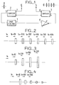
- a generator of fixed and / or mobile pulses with arbitrarily large delay and controllable by increments, using a simple delay line with fixed delay is characterized in that it comprises a variable gain amplifier connected between the output and the input of said line, compensating for the losses suffered by the pulses passing through the lines and in the input and output circuits, the assembly of said line and of the amplifier constituting the generator of fixed pulses and in that it further comprises means connectable to said fixed pulse generator acting on the phase shift of the pulses which it delivers and transforms said fixed pulses into mobile pulses.
- the pulse generator according to the invention had to compensate for the losses undergone during the propagation of said pulses in the line used, losses all the greater as the distance to be traveled in the line material is greater if it is desired to obtain pulse train output or a fixed pulse with large delay.
- these drawbacks are linked to delay lines called surface waves or volume waves. If we know how to master in this technique the production of delay lines with simple "echo", characterized by a delay of the order of a microsecond or a few microseconds, it is no longer the same for pulse lines or multiple echoes or large lines delay of the order of ten or a few tens of microseconds.
- the stability of the system then implies that the gain of the amplifier is periodically lowered so as to prevent the oscillation of the system, lowering of gain which the specialist knows how to achieve by several simple and inexpensive methods among which may be mentioned, for example as an example, the insertion of a modulator in series with the amplifier, the cutting of the supply voltage of one or more stages of the amplifier or the action on the gain control of the amplifier if it exists.
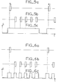
- Periodic reduction of the gain can take place between the different pulse trains corresponding to the pulses injected at the input (FIG. 5) and also while the signal is in transit in the delay line (FIG. 6).
- Controlling the gain is all the more necessary since it is necessary to prevent the looped system according to the invention from oscillating. To do this, the gain of the amplifier must be reduced periodically. This can be done in different ways, such as those mentioned above.
- FIG. 5 shows on a diagram as a function of time how the periodic reduction of the gain can take place between the different trains of pulses corresponding to the pulses injected at the input of the system.
- FIG. 5a shows two successive input signals A1 and A2.
- FIG. 5b shows the train of output pulses at constant amplitude
- FIG. 5c represents the variation of the gain G of the amplifier as a function of time.
- FIG. 6 shows the control of the gain G of the amplifier in the case where the latter is lowered during the transit of the pulse in the delay line.
- the gain control can also be done with a modulator connected in series with the amplifier. It has been indicated in the introduction to the present description that the invention is particularly advantageous for delivering pulse trains. This does not preclude the possibility of obtaining, if necessary, a single pulse. To do this, we use a modulator that we have at the output of the system and that we control so as to be on only for the chosen pulse.
- Figure 7 shows schematically the corresponding arrangement with operating curves.
- Figure 7a schematically reproduces Figure 1 with the delay line 1 and the amplifier 6 and the two couplers 2 and 3 input and output and the modulator 9 connected to the output of the system.
- FIG. 7b shows the input signal A 1 , at time to.
- FIG. 7c shows the control of the modulator as a function of time. It is blocked for example between time to and time to + n ⁇ t, ⁇ t being the fixed delay of delay line 1, then passing to time (n + 1) t and blocked again.
- curve 7d which represents the train of output pulses of the system that the chosen signal, the (n + 1) th for example, is delivered during the opening of the modulator 9.
- a device comprising a simple delay line with a single echo and a delay ⁇ t that it is relatively easy to construct when a long delay line, of delay nx ⁇ t, n being an integer, or a line with multiple echoes of elementary delay ⁇ t, with the level of the n th echo perfectly controllable, is not currently easy to be constructed in the surface wave and volume wave technique.
- the degradation of the signal to noise ratio from one pulse to the next is very low; in fact, in the case for example where the level of successive echoes is kept constant, the calculation shows that if the noise factor of the amplifier is F, the degradation of the signal to noise ratio between the first and n th delayed pulses is of the form:
- the pulse generator according to the invention found applications of choice in the radar field where in particular it could be used as a generator of fixed and / or mobile echoes, in a test device, test device for measuring the phase stability of radar pilots, radar pilot with improved phase stability by phase control on the successive pulses delivered by the generator, and also usable in a radar jammer using the successive pulses leaving the delay line loop to create numerous echoes shifted in distance and with the same characteristics.
- the oscillation of the Stalo and the Coho is not strictly repetitive from one recurrence to another during the round trip time of the radar pulse.
- the oscillation shows a non-constancy of the phase of the signal received once demodulated by the Stalo and the Coho, even in the case of a perfectly fixed obstacle.
- This phase variation amounts to superimposing on each received fixed echo, a parasitic mobile echo whose relative amplitude relative to the fixed fixed echo is proportional to the cumulative phase variations of the Stalo and of the Coho during the round trip time between a recurrence and the next.
- the generator according to the invention can be used as equipment for testing a radar system; is injected at the input of the system for example shown in Figure 1, a sample of the radar emission pulse, this sample being able to be taken at any point of the emission chain, even close to the antenna and even after radiation by the latter.
- the output of the system there is a whole series of perfectly stable echoes simulating fixed echoes and having the advantage of having a significant signal-to-noise ratio whatever the rank of the echoes and of being perfectly fixed, c that is to say characterized by a perfectly constant time shift.
- Circuit 10 represents the generator of fixed echoes as shown for example in FIG. 1. The output of this circuit 10 is connected to a coupler 11 connected to two parallel channels 12 and 13.
- One of them 12 transmits the echoes fixed to an output coupler 14, the other 13 comprises in series a variable attenuator 15 followed by a phase shifter 16 with electronic control, preferably.
- This channel 13 thus creates mobile echoes which are transmitted through the output coupler 14 to the output S of the complete system which receives the mixture of fixed and mobile echoes.
- the electronically controlled phase shifter 16 changes state after each echo train or, which amounts to the same thing, before each pulse entering the echo generator as shown in FIG. 9 where the curve 9a represents the phase Q displayed on the phase shifter 16 as a function of time t and FIG. 9b the echo trains obtained.
- this action transforms the fixed echoes present at the input of the phase shifter into so-called mobile echoes, that is to say, simulating the waves returned by the moving targets.
- the radial speed of displacement of the target thus simulated can vary at the option of the user, which varies the difference in phase shift ⁇ between a recurrence and the next introducing a delay , being the frequency of the radar.
- the attenuator 15 connected to the phase shifter 16 before the output coupler 14 makes it possible to measure the level of the mobile echoes superimposed on the fixed echoes.
- the fixed echo generator according to the invention can also be used for measuring the stability of local radar oscillators.
- the quantity measured is the variation of the difference between the phase of the signal at an instant t and the phase of the signal at the instant t + 66, ⁇ being generally fixed at several tens of microseconds or even a few hundred.
- Figure 10 shows the assembly of this test equipment.
- the local oscillator 17 whose stability is to be measured is connected to the fixed echo generator 10, according to the invention, through a switch 18.
- the output of the generator 10 is connected to a mixer 19 also connected to the local oscillator 17.
- the operation of this device is as follows.
- the analysis in the circuit 20 of the variations of the output signals of the mixer 19 gives the quantity to be measured for discrete values of ⁇ equal to n times the elementary delay t of the line.
- the measurement thus made is simple and reliable and does not have the limitations of conventional methods generally based on the use of a coherent oscillator whose own instability limits the accuracy of the measurement.
- a radar pilot with high phase stability is controlled by the successive pulses leaving the delay line.
- the successive pulses leaving the delay line loop according to the invention are used to create numerous echoes offset in distance and with the same characteristics.
Landscapes
- Engineering & Computer Science (AREA)
- Radar, Positioning & Navigation (AREA)
- Remote Sensing (AREA)
- Computer Networks & Wireless Communication (AREA)
- Physics & Mathematics (AREA)
- General Physics & Mathematics (AREA)
- Radar Systems Or Details Thereof (AREA)
- Amplifiers (AREA)
Applications Claiming Priority (2)
| Application Number | Priority Date | Filing Date | Title |
|---|---|---|---|
| FR8210704A FR2529039A1 (fr) | 1982-06-18 | 1982-06-18 | Generateur d'impulsions fixes et/ou mobiles a retard arbitrairement grand et controlable par increments |
| FR8210704 | 1982-06-18 |
Publications (1)
| Publication Number | Publication Date |
|---|---|
| EP0097565A1 true EP0097565A1 (de) | 1984-01-04 |
Family
ID=9275166
Family Applications (1)
| Application Number | Title | Priority Date | Filing Date |
|---|---|---|---|
| EP83401157A Withdrawn EP0097565A1 (de) | 1982-06-18 | 1983-06-07 | Generator mit festen und/oder verschiebbarer Impulsen mit einer beliebig grossen und in Stufen steuerbaren Verzögerung |
Country Status (3)
| Country | Link |
|---|---|
| EP (1) | EP0097565A1 (de) |
| JP (1) | JPS595732A (de) |
| FR (1) | FR2529039A1 (de) |
Cited By (1)
| Publication number | Priority date | Publication date | Assignee | Title |
|---|---|---|---|---|
| EP0282195A2 (de) * | 1987-03-06 | 1988-09-14 | Raytheon Company | Vorrichtung zur Überwachung der Radarleistungsfähigkeit |
Citations (8)
| Publication number | Priority date | Publication date | Assignee | Title |
|---|---|---|---|---|
| US3113268A (en) * | 1961-03-31 | 1963-12-03 | Ling Temco Vought Inc | Coherent multi-mode repeater |
| US3883810A (en) * | 1972-05-26 | 1975-05-13 | Dassault Electronique | Device for the use in frequency of a short duration electrical signal |
| GB1467000A (en) * | 1974-01-25 | 1977-03-16 | Marconi Co Ltd | Electrical methods and apparatus for radar jamming |
| DE2616770A1 (de) * | 1976-04-15 | 1977-10-27 | Siemens Ag | Schaltungsanordnung zur erzeugung eines simulierten bewegtzielechosignales |
| GB1532777A (en) * | 1976-01-23 | 1978-11-22 | Emi Ltd | Apparatus for providing a succession of output signals from a single input signal |
| US4145691A (en) * | 1971-12-13 | 1979-03-20 | Rca Corporation | RF Burst signal recirculation memory system having a diplexed feedback loop |
| US4164741A (en) * | 1968-09-13 | 1979-08-14 | The United States Of America As Represented By The Secretary Of The Air Force | Deception circuitry for automatic range gate tracking in fire control radar |
| US4328496A (en) * | 1958-08-27 | 1982-05-04 | The United States Of America As Represented By The Secretary Of The Navy | Delay control for a pulse repeat-back jamming system |
-
1982
- 1982-06-18 FR FR8210704A patent/FR2529039A1/fr not_active Withdrawn
-
1983
- 1983-06-07 EP EP83401157A patent/EP0097565A1/de not_active Withdrawn
- 1983-06-17 JP JP58108004A patent/JPS595732A/ja active Pending
Patent Citations (8)
| Publication number | Priority date | Publication date | Assignee | Title |
|---|---|---|---|---|
| US4328496A (en) * | 1958-08-27 | 1982-05-04 | The United States Of America As Represented By The Secretary Of The Navy | Delay control for a pulse repeat-back jamming system |
| US3113268A (en) * | 1961-03-31 | 1963-12-03 | Ling Temco Vought Inc | Coherent multi-mode repeater |
| US4164741A (en) * | 1968-09-13 | 1979-08-14 | The United States Of America As Represented By The Secretary Of The Air Force | Deception circuitry for automatic range gate tracking in fire control radar |
| US4145691A (en) * | 1971-12-13 | 1979-03-20 | Rca Corporation | RF Burst signal recirculation memory system having a diplexed feedback loop |
| US3883810A (en) * | 1972-05-26 | 1975-05-13 | Dassault Electronique | Device for the use in frequency of a short duration electrical signal |
| GB1467000A (en) * | 1974-01-25 | 1977-03-16 | Marconi Co Ltd | Electrical methods and apparatus for radar jamming |
| GB1532777A (en) * | 1976-01-23 | 1978-11-22 | Emi Ltd | Apparatus for providing a succession of output signals from a single input signal |
| DE2616770A1 (de) * | 1976-04-15 | 1977-10-27 | Siemens Ag | Schaltungsanordnung zur erzeugung eines simulierten bewegtzielechosignales |
Cited By (2)
| Publication number | Priority date | Publication date | Assignee | Title |
|---|---|---|---|---|
| EP0282195A2 (de) * | 1987-03-06 | 1988-09-14 | Raytheon Company | Vorrichtung zur Überwachung der Radarleistungsfähigkeit |
| EP0282195A3 (en) * | 1987-03-06 | 1990-05-30 | Raytheon Company | Radar performance monitor |
Also Published As
| Publication number | Publication date |
|---|---|
| FR2529039A1 (fr) | 1983-12-23 |
| JPS595732A (ja) | 1984-01-12 |
Similar Documents
| Publication | Publication Date | Title |
|---|---|---|
| EP0258917B1 (de) | Frequenzmoduliertes Dauerstrichradar zur Entfernungsmessung | |
| EP0496329B1 (de) | Im Satellit eingebautes Seestreustrahlungsmessgerät | |
| EP0818691B1 (de) | Verfahren und Vorrichtung zur Zielerfassung für Doppler Radargeräte mit Hilfe von breitbandigen eindeutigen Pulsen | |
| EP2535733B1 (de) | Kompaktsystem zur Hochdruck-Höhenmessung | |
| EP0182418A1 (de) | Laufzeitsimulator für ein Entfernungsmessgerät mit Dauerstrichfrequenzmodulation | |
| WO1992019985A1 (fr) | Systeme de mesure de distances a echo avec dispositif de calibration | |
| FR2729764A1 (fr) | Radar a champ angulaire instantane important et haut pouvoir instantane de resolution angulaire, notamment pour autodirecteur de missile | |
| EP0309350A1 (de) | Messanordnung für Interdmodulationsprodukte eines Empfangssystem | |
| EP0080927B1 (de) | Empfänger für eine Sonde zum Detektieren und Messen von Phänomenen der Erdumgebung | |
| FR2551231A1 (fr) | Circuit de controle parametrique en courant alternatif | |
| EP0493189A1 (de) | Digitalkodierte Impulssignalverarbeitung | |
| FR2727763A1 (fr) | Procede et dispositif pour determiner la vitesse d'un mobile au moyen d'un radar ou sonar a compression d'impulsion | |
| EP0073162B1 (de) | Verfahren zum Schützen eines Radars von Störsendungen und Radargerät zum Ausführen dieses Verfahrens | |
| EP0022410B1 (de) | Sondiergerät zum Bestimmen und Messen relativer Phänomene in der Umgebung des Erdballs | |
| EP0028182A1 (de) | Frequenzmoduliertes Bord-Radargerät und seine Anwendung bei einem sich selbst lenkenden Flugkörper | |
| FR2639775A1 (fr) | Dispositif de correction de phase induite par le fonctionnement en classe c de l'amplificateur " etat solide " et chaine radar utilisant un tel dispositif | |
| EP0097565A1 (de) | Generator mit festen und/oder verschiebbarer Impulsen mit einer beliebig grossen und in Stufen steuerbaren Verzögerung | |
| FR2632420A1 (fr) | Procede et dispositif de compensation de la vitesse du fouillis dans un radar doppler coherent a vitesse ambigue variable | |
| EP4124886A1 (de) | Vorrichtung und verfahren zur radarmessung mit doppelter radarsignalgenerierung | |
| EP0390657B1 (de) | Messung der Sende-Empfangsstabilität in einem Radargerät | |
| EP0064900A1 (de) | Elektromagnetisches System mit Korrelation-Detektion und Annäherungszünder mit besagtem System | |
| EP0016674B1 (de) | Frequenzdiskriminator und damit stabilisierter Oszillator | |
| FR2462717A1 (fr) | Systeme de detection electromagnetique a compression d'impulsions destine notamment a realiser un telemetre laser | |
| EP3516414B1 (de) | Vorrichtung zur erzeugung eines kontinuierlichen trägersignals von einem referenzimpulssignal | |
| EP0068572B1 (de) | Synchronisierungs-Vorrichtung insbesondere für ein Abbildungsgerät eines Impulsradars |
Legal Events
| Date | Code | Title | Description |
|---|---|---|---|
| PUAI | Public reference made under article 153(3) epc to a published international application that has entered the european phase |
Free format text: ORIGINAL CODE: 0009012 |
|
| AK | Designated contracting states |
Designated state(s): DE GB IT NL |
|
| 17P | Request for examination filed |
Effective date: 19840419 |
|
| STAA | Information on the status of an ep patent application or granted ep patent |
Free format text: STATUS: THE APPLICATION IS DEEMED TO BE WITHDRAWN |
|
| 18D | Application deemed to be withdrawn |
Effective date: 19851126 |
|
| RIN1 | Information on inventor provided before grant (corrected) |
Inventor name: PEYRAT, ANDRE |