EP0080893B1 - Sicherheitseinrichtung - Google Patents
Sicherheitseinrichtung Download PDFInfo
- Publication number
- EP0080893B1 EP0080893B1 EP19820306360 EP82306360A EP0080893B1 EP 0080893 B1 EP0080893 B1 EP 0080893B1 EP 19820306360 EP19820306360 EP 19820306360 EP 82306360 A EP82306360 A EP 82306360A EP 0080893 B1 EP0080893 B1 EP 0080893B1
- Authority
- EP
- European Patent Office
- Prior art keywords
- calliper
- wheel
- callipers
- boss
- adjustable
- Prior art date
- Legal status (The legal status is an assumption and is not a legal conclusion. Google has not performed a legal analysis and makes no representation as to the accuracy of the status listed.)
- Expired
Links
- 238000010276 construction Methods 0.000 description 1
- 230000000994 depressogenic effect Effects 0.000 description 1
- 239000007787 solid Substances 0.000 description 1
Images


Classifications
-
- B—PERFORMING OPERATIONS; TRANSPORTING
- B60—VEHICLES IN GENERAL
- B60R—VEHICLES, VEHICLE FITTINGS, OR VEHICLE PARTS, NOT OTHERWISE PROVIDED FOR
- B60R25/00—Fittings or systems for preventing or indicating unauthorised use or theft of vehicles
- B60R25/01—Fittings or systems for preventing or indicating unauthorised use or theft of vehicles operating on vehicle systems or fittings, e.g. on doors, seats or windscreens
- B60R25/09—Fittings or systems for preventing or indicating unauthorised use or theft of vehicles operating on vehicle systems or fittings, e.g. on doors, seats or windscreens by restraining wheel rotation, e.g. wheel clamps
- B60R25/093—Fittings or systems for preventing or indicating unauthorised use or theft of vehicles operating on vehicle systems or fittings, e.g. on doors, seats or windscreens by restraining wheel rotation, e.g. wheel clamps comprising ground-engaging means
-
- B—PERFORMING OPERATIONS; TRANSPORTING
- B60—VEHICLES IN GENERAL
- B60R—VEHICLES, VEHICLE FITTINGS, OR VEHICLE PARTS, NOT OTHERWISE PROVIDED FOR
- B60R25/00—Fittings or systems for preventing or indicating unauthorised use or theft of vehicles
- B60R25/01—Fittings or systems for preventing or indicating unauthorised use or theft of vehicles operating on vehicle systems or fittings, e.g. on doors, seats or windscreens
- B60R25/02—Fittings or systems for preventing or indicating unauthorised use or theft of vehicles operating on vehicle systems or fittings, e.g. on doors, seats or windscreens operating on the steering mechanism
- B60R25/022—Fittings or systems for preventing or indicating unauthorised use or theft of vehicles operating on vehicle systems or fittings, e.g. on doors, seats or windscreens operating on the steering mechanism operating on the steering wheel, e.g. bars locked to the steering wheel rim
- B60R25/0225—Fittings or systems for preventing or indicating unauthorised use or theft of vehicles operating on vehicle systems or fittings, e.g. on doors, seats or windscreens operating on the steering mechanism operating on the steering wheel, e.g. bars locked to the steering wheel rim using a rod locked on the steering wheel rim
Definitions
- This invention relates to a security device for use in preventing the unauthorised rotation of a wheel such as a steering wheel, an undriven wheel of a vehicle, a control wheel for industrial apparatus, or any other wheel where it is desired to prevent unauthorised movement of the wheel.
- the device may be applied for instance to . wheels of box trailers, trailer tents, caravans, horse boxes, boat trailers, towable industrial appliances such as air compressors winches etc., goods trailers or any vehicle which possesses an accessible undriven wheet. It is equally suitable for use on wheels fitted with pneumatic or solid tyres.
- a steering wheel of a motor vehicle to a tiller wheel of a boat, to a control wheel for opening a sluice gate or any similar wheel.
- An object of the invention is to provide an easily portable security device which may be applied with very little effort to a vehicle wheel or a steering wheel or any other wheel.
- the device is so arranged that while it may allow a limited movement of the wheel it prevents the wheel being turned through more than a fraction of a full turn and thus would prevent a vehicle being driven away, or a machine or appliance being turned on, or a boat being steered, for example.
- the security device will virtually immobilise the vehicle to which it is attached or, if attached to a steering wheel will virtually prevent the vehicle being steered.
- DE-U-7 735 706 shows a security device for attachment to a wheel comprising a boss member and three spaced callipers, two of the callipers being pivoted to the boss and the third calliper being adjustably lockable on the boss, the callipers being arranged so that when applied to a wheel they embrace both sides of the wheel and are spaced around the periphery of the wheel, one of the callipers being formed as a slidable calliper so as to allow for the adjustable locking aspect of the device and being arranged to slide across the face of the boss member in guide means formed on or in the boss member.
- GB-A-1269813 also shows an anti-theft device which uses an extension of a calliper as a means for preventing wheel rotation.
- the present invention relates to a security device for attachment to a wheel comprising a boss member and at least three spaced callipers two of the three callipers being pivoted to the boss and the third calliper being adjustably lockable on the boss the callipers being arranged so that when applied to a wheel they embrace both sides of the wheel and are spaced around the periphery of the wheel.
- the invention is characterised by this, that the callipers may be arranged at any circumferential location around the wheel and that the third calliper which is not pivoted to the boss carries an extension capable of preventing rotation of the wheel by coming into contact with fixed structure (such as the ground) but not normally in contact with the fixed structure.
- the third calliper is preferably formed as a loose or slidable calliper so as to allow for the adjustable locking aspect of the device.
- the adjustable calliper is preferably arranged to slide across the face of the boss member in guide means formed on or in the boss member, or formed by the other two callipers.
- Stops may be provided to limit movement of two of the callipers which are pivoted to the plate.
- the lever may be pivoted to the boss member and arranged to engage notches in the adjustable calliper so as to enable the user to draw the callipers tightly onto the wheel.
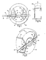
- the security device which is shown applied to a wheel 10, comprises a first boss plate 11 and a second boss plate 11a. Pivoted to the first boss plate 11 are a pair of callipers 12 and 13 and pivoted to the second boss plate 11a are a pair of callipers 12a and 13a.
- the callipers extend around the edge of the wheel and beyond the edge on the other side of the wheel as shown in dotted line in the right hand portion of Figure 1 and also shown in Figure 1 a.
- the way in which the callipers 12 and 13 are pivoted to the boss plate 11 is illustrated in Figures 3 and 4. Rivets 17, 18 extend through holes in the link 16 and through holes in the ends of the callipers 12 and 13 and are secured in further holes in the boss plate 11.
- a loose or adjustable calliper 19 which has an extension 20 adapted to engage the ground when the device is applied to a wheel as shown in Figure 2.
- the adjustable calliper 19 has a row of holes 21 which enable the calliper to be locked into position by applying a padlock 22 through one of the holes 21 into a corresponding hole in the boss plate 11.
- the remote end of the loose calliper 19 is curled round at 23 to engage the corresponding end of boss plate 11a as seen in Figure 2 particularly.
- Figure 1 shows the way in which the device is capable of adjustment of accommodate various sizes of wheels.
- the wheel 10a is of larger diameter than the wheel 10 but as can be seen from the dotted positions of the boss plates 11, 11 a and the corresponding positions of the callipers the device may be arranged to lock a larger diameter wheel, or a smaller diameter wheel as desired.
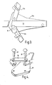
- boss plate 25 In the embodiment of the invention shown in Figures 5, to 11 there is only a single boss plate 25 (Figure 5 and 5a).
- the boss plate 25 is provided with a bracket 26 welded to the boss plate and adapted to receive the adjustable or loose calliper 27.
- the boss plate 25 also has two stops 28 which are in the form of short plates welded to the boss plate and act as stops which limit the pivoting movement of a pair of callipers 29, only one of which is shown in Figure 8. Callipers 29 are attached to boss plate 25 so as to be free to pivot by means of rivets 30.
- calliper 29 The shape of the calliper 29 is shown more clearly in Figures 6 and 6a and the shape of the calliper 27 is shown'more clearly in Figures 7 and 7a. It will be seen that the calliper 29 has an extension 29a adapted to wrap around a wheel so that the calliper can engage both sides of a wheel. Similarly calliper 27 has an extension 27a to wrap around the wheel.
- Calliper 27 also has a row of holes 28 which are adapted to register with a hole 29b in the end of the boss plate 25. By sliding the adjustable calliper 27 in the bracket 26 and then putting a locking device such as a padlock through registering one of holes 28 and hole 29b, the calliper 27 may be locked in position.
- Figure 9 the device is shown applied to a trailer wheel, the boss plate 25 and two callipers 29 are first offered up to the wheel, with one of the callipers 29 being passed underneath the mud-guard so that the extensions 29a, or returns of the callipers, pass on the far side of the wheel.
- the loose calliper 27 is then pushed through the bracket 26 at the same time holding the boss plate 25 firmly so that the callipers 29 engage the wheel.
- a padlock 31 is placed through one of the holes 28 in the loose calliper 27 and in a hole formed in the end of the boss plate 25 (shown in Figure 8).
- the whole device is firmly held on the wheel and if somebody should attempt to move the trailer the end 27b of the device engages against the ground or against the fixed part of the trailer thus preventing movement of more than a few inches.
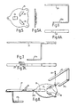
- the embodiment shown in Figure 12 is different in that although it has a central boss plate 32 and a pair of pivoted calliper arms 33 and 34, the construction of the loose calliper arm 35 is changed.
- the loose calliper arm passes through a bracket 36 which performs a number of functions. Firstly it provides a guide for the loose calliper arm 35. Secondly it provides at 36a and 36b the stops for the pivoted callipers 33 and 34, and thirdly it provides by means of an aperture 37 provision for the locking device.
- the locking device in this instance can be a push button type lock 38 which enters the hole 37 in the bracket 36 and engages the loose calliper 35 so as to lock it in position.
- a pivoted lever 39 pivoted at 40 onto the boss plate 32.
- This lever has a pin 40a adapted to engage in any one of a number of half round slots or notches 41 in the lower side of the loose calliper 35.
- the lever By engaging the calliper 35 in successive brackets 42 and 36 and then engaging the pin 40a of pivoted lever 39 in an appropriate notch 41, the lever can be moved clockwise as seen in Figure 12, so as to draw the calliper 35 to the right and thus tighten up callipers 33, 34 and 35.
- the press button lock 37 may be applied so as to lock the calliper 35 in place.
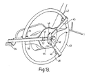
- FIG. 13 shows a security device embodying the invention applied to a steering wheel 43 of a motor vehicle.
- the device includes a boss plate 44, pivoted calliper arms 45 and 46 each of which has a sharply bent return or extension 47, 48.
- the returns 47 and 48 engage round the rim of the steering wheel 43.
- the pivoting movement of the callipers 45 and 46 is limited by a plate 48 attached to the boss plate 44.
- the boss plate 44 also has a bracket 49 through which a loose or adjustable calliper 50 extends.
- the adjustable calliper 50 has an extension 51 or return portion to engage the rim of the steering wheel and also has a row of holes 52.
- the adjustable calliper 50 can be locked in place by means of a push button lock 53 which has an extension (not shown) which passes through a hole 52 in the adjustable calliper 50 and into a hole (not shown) in the boss plate 44.
- the outward extension 54 of the adjustable calliper 50 is arranged to engage against a fixed portion of the motor vehicle such as the seat or door, thus preventing the steering wheel being turned.
- the lock incorporated in this arrangement is similar to the lock incorporated in the Figure 12 arrangement and is a known integral barrel lock type. It locks the lever by engaging a stud, formed at the end of the barrel in a tongue formed on a locking lever. When the lever has reached the end of its travel the barrel is depressed causing the stud to enter a hole in the tongue. A pole retains the barrel in this position until the key is inserted and turned to disengage the pole allowing the barrel to pop out. Since this type of lock is well-known it is not illustrated in detail.
- boss plate 25 serves to prevent access to the wheel nuts and is suitably shaped to this end.
- Towable vehicles whilst uncoupled and unattended, are particularly vulnerable to illicit removal.
- the security device of the invention im- mobilises the vehicle by preventing rotation of the wheel.
- the machinery if applied to a steering wheel or other wheel which operates machinery etc., the machinery cannot be operated or the vehicle cannot be steered with the device in position.
Landscapes
- Engineering & Computer Science (AREA)
- Mechanical Engineering (AREA)
- Lock And Its Accessories (AREA)
- Vehicle Cleaning, Maintenance, Repair, Refitting, And Outriggers (AREA)
Claims (9)
Priority Applications (1)
| Application Number | Priority Date | Filing Date | Title |
|---|---|---|---|
| AT82306360T ATE27431T1 (de) | 1981-12-01 | 1982-11-30 | Sicherheitseinrichtung. |
Applications Claiming Priority (4)
| Application Number | Priority Date | Filing Date | Title |
|---|---|---|---|
| GB8136220 | 1981-12-01 | ||
| GB8136220 | 1981-12-01 | ||
| GB8212767A GB2110175A (en) | 1981-12-01 | 1982-04-30 | Wheeled vehicle theft deterrent |
| GB8212767 | 1982-04-30 |
Publications (2)
| Publication Number | Publication Date |
|---|---|
| EP0080893A1 EP0080893A1 (de) | 1983-06-08 |
| EP0080893B1 true EP0080893B1 (de) | 1987-05-27 |
Family
ID=26281428
Family Applications (1)
| Application Number | Title | Priority Date | Filing Date |
|---|---|---|---|
| EP19820306360 Expired EP0080893B1 (de) | 1981-12-01 | 1982-11-30 | Sicherheitseinrichtung |
Country Status (5)
| Country | Link |
|---|---|
| EP (1) | EP0080893B1 (de) |
| AU (1) | AU562201B2 (de) |
| CA (1) | CA1196791A (de) |
| DE (1) | DE3276417D1 (de) |
| GB (1) | GB2110175A (de) |
Cited By (2)
| Publication number | Priority date | Publication date | Assignee | Title |
|---|---|---|---|---|
| WO2005108174A1 (en) * | 2004-05-06 | 2005-11-17 | John Clarke | Vehicle wheel immobilizer |
| DE102022103157B3 (de) | 2022-02-10 | 2023-02-16 | Dr. Ing. H.C. F. Porsche Aktiengesellschaft | Sicherungsanordnung für ein Fahrzeugrad |
Families Citing this family (36)
| Publication number | Priority date | Publication date | Assignee | Title |
|---|---|---|---|---|
| GB2124566B (en) * | 1982-06-22 | 1985-11-13 | John Robert Tillard | Immobilising vehicles |
| IL74860A0 (en) * | 1985-01-22 | 1985-07-31 | Izhak Givati | Motor vehicle accessory particularly useful for protecting the vehicle against theft |
| US4768359A (en) * | 1986-07-31 | 1988-09-06 | Wade Mark W | Wheel lock |
| GB8628183D0 (en) * | 1986-11-25 | 1986-12-31 | Richards N W | Foldable wheel clamp |
| US4723426A (en) * | 1986-12-15 | 1988-02-09 | Fernand Beaudoin | Wheel clamp attachment |
| GB8715930D0 (en) * | 1987-07-07 | 1987-08-12 | Hedges L | Wheel clamp |
| US4854144A (en) * | 1987-08-17 | 1989-08-08 | Double Helix Enterprises | Vehicle immobilization device |
| US4949561A (en) * | 1989-04-07 | 1990-08-21 | Wolo Manufacturing Corporation | Steering wheel lock bar |
| FR2660610A1 (fr) * | 1989-07-18 | 1991-10-11 | Bedouin Andre | Anti vol sur roues de voitures. |
| JPH06500750A (ja) * | 1990-09-06 | 1994-01-27 | エイ.ビー.エイ.マーケティング ピーティワイ リミテッド | 自動車用ハンドルロック |
| AU645350B2 (en) * | 1990-09-06 | 1994-01-13 | A.B.A. Marketing Pty Limited | Vehicle steering-wheel lock |
| GB2251416B (en) * | 1991-01-05 | 1993-09-22 | Lancashire Clamping Company Li | Wheel clamps |
| GB2260955A (en) * | 1991-10-29 | 1993-05-05 | Philip Denman | Wheel clamps |
| GB2271969A (en) * | 1992-10-09 | 1994-05-04 | Graham Cox | Vehicle security wheel clamp |
| US5284036A (en) * | 1992-12-02 | 1994-02-08 | Rosenbaum Nathan B | Tamper-resistant security lock for cargo container doors |
| US5613383A (en) * | 1993-01-21 | 1997-03-25 | Winner International Royalty Corporation | Vehicle security device |
| GB9303071D0 (en) * | 1993-02-16 | 1993-03-31 | Cestria Fabrications Ltd | Vehicle wheel clamp |
| IT1272358B (it) * | 1993-04-23 | 1997-06-23 | Andrea Mombelli | Antifurto per autoveicoli applicabile ad una ruota |
| GB2279632A (en) * | 1993-07-02 | 1995-01-11 | Grayspeed Leisure Products Lim | Wheel clamp |
| US5333477A (en) * | 1993-07-20 | 1994-08-02 | Phillip Davis | Vehicle parking boot |
| US5437171A (en) * | 1993-08-20 | 1995-08-01 | Owen; Joseph L. | Device for preventing free rotation of a wheel of a stationary vehicle |
| NL9301896A (nl) * | 1993-11-03 | 1995-06-01 | Unimeta Nederland B V | Kleminrichting voor een wiel. |
| GB9400365D0 (en) * | 1994-01-11 | 1994-03-09 | Sedgeman Graham L | Clamping device |
| GB9400860D0 (en) * | 1994-01-18 | 1994-03-16 | Dewman Philip | Wheelclamp |
| US5537847A (en) * | 1994-03-07 | 1996-07-23 | Dalton; Michael | Anti-theft device for motor vehicles |
| FR2723900B1 (fr) * | 1994-08-23 | 1997-12-12 | Lebrun Pierre | Aide au desserrage des boulons et roues et antivol pour automobile |
| WO1996013410A1 (en) * | 1994-10-31 | 1996-05-09 | Barker J W | Vehicle safety and security device |
| USD373942S (en) | 1994-12-14 | 1996-09-24 | Sears Peter A | Chain tightener |
| US5755123A (en) * | 1995-10-10 | 1998-05-26 | Winner International Royalty Corporation | Steering wheel protection device |
| US5715711A (en) * | 1996-02-08 | 1998-02-10 | Jennison; Thomas | Portable wheel immobilizing device |
| USD383372S (en) | 1996-04-10 | 1997-09-09 | Winner International Royalty Corporation | Steering wheel guard |
| US5855128A (en) * | 1997-09-10 | 1999-01-05 | Winner International Royalty Corporation | Steering wheel protection device |
| US5996721A (en) * | 1998-02-02 | 1999-12-07 | Winner International Royalty Llc | Steering wheel and air bag protection device |
| US6109076A (en) * | 1999-05-06 | 2000-08-29 | Master Lock Company | Automobile and airbag anti-theft device |
| US6125672A (en) * | 2000-03-03 | 2000-10-03 | Diez; Adalberto | Security devices for vehicle |
| US10895092B2 (en) * | 2019-04-16 | 2021-01-19 | Richard Rapp | Tire anchoring system |
Family Cites Families (3)
| Publication number | Priority date | Publication date | Assignee | Title |
|---|---|---|---|---|
| DE7735706U1 (de) * | Hartesveldt, Jean-Jacques Van, Aerdenhout (Niederlande) | |||
| US1502933A (en) * | 1923-08-22 | 1924-07-29 | John M Allen | Auto lock |
| GB1269813A (en) * | 1968-04-16 | 1972-04-06 | Stayput Engineering Pty Ltd | A motor vehicle anti-theft device |
-
1982
- 1982-04-30 GB GB8212767A patent/GB2110175A/en not_active Withdrawn
- 1982-11-30 DE DE8282306360T patent/DE3276417D1/de not_active Expired
- 1982-11-30 CA CA000416707A patent/CA1196791A/en not_active Expired
- 1982-11-30 EP EP19820306360 patent/EP0080893B1/de not_active Expired
- 1982-12-01 AU AU91036/82A patent/AU562201B2/en not_active Ceased
Cited By (3)
| Publication number | Priority date | Publication date | Assignee | Title |
|---|---|---|---|---|
| WO2005108174A1 (en) * | 2004-05-06 | 2005-11-17 | John Clarke | Vehicle wheel immobilizer |
| US7107802B2 (en) | 2004-05-06 | 2006-09-19 | John Clarke | Wheel immobilizer |
| DE102022103157B3 (de) | 2022-02-10 | 2023-02-16 | Dr. Ing. H.C. F. Porsche Aktiengesellschaft | Sicherungsanordnung für ein Fahrzeugrad |
Also Published As
| Publication number | Publication date |
|---|---|
| AU562201B2 (en) | 1987-06-04 |
| GB2110175A (en) | 1983-06-15 |
| AU9103682A (en) | 1983-06-09 |
| CA1196791A (en) | 1985-11-19 |
| EP0080893A1 (de) | 1983-06-08 |
| DE3276417D1 (en) | 1987-07-02 |
Similar Documents
| Publication | Publication Date | Title |
|---|---|---|
| EP0080893B1 (de) | Sicherheitseinrichtung | |
| KR930000288B1 (ko) | 조향핸들 체결구 | |
| US4164131A (en) | Automobile anti-theft device | |
| US4526021A (en) | Spare tire lock | |
| US4033160A (en) | Bicycle lock | |
| US3539152A (en) | Spare tire hoist | |
| US5547045A (en) | Adjustable wheel chocks for tandem wheeled vehicles | |
| US3542413A (en) | Apparatus for storing spare wheels under vehicles | |
| US5385038A (en) | Vehicle wheel clamp | |
| US7412859B2 (en) | Device for immobilising a motor vehicle | |
| US4175410A (en) | Vehicle wheel engageable blocking device | |
| US6824121B2 (en) | Wheel securing device | |
| US5461891A (en) | Apparatus for secure positioning over and around a steering wheel and steering column to prevent theft | |
| AU696172B2 (en) | Automobile security device | |
| US5460021A (en) | Golf car security apparatuses | |
| US6705137B2 (en) | Lock device for semitrailers and the like | |
| US4013203A (en) | Lockable tire carrier | |
| US4750341A (en) | Vehicle anti-theft device | |
| US5996721A (en) | Steering wheel and air bag protection device | |
| US4977974A (en) | Locking device for automobiles | |
| US4538435A (en) | Steering column lock for heavy-duty vehicles | |
| US7503195B2 (en) | Wheel lock apparatus | |
| GB2179607A (en) | Wheel immobilisers | |
| US5707111A (en) | Vehicle seat locking system | |
| US5454243A (en) | Trailer locking system |
Legal Events
| Date | Code | Title | Description |
|---|---|---|---|
| PUAI | Public reference made under article 153(3) epc to a published international application that has entered the european phase |
Free format text: ORIGINAL CODE: 0009012 |
|
| AK | Designated contracting states |
Designated state(s): AT BE CH DE FR GB IT LI LU NL SE |
|
| 17P | Request for examination filed |
Effective date: 19831206 |
|
| 17Q | First examination report despatched |
Effective date: 19851001 |
|
| GRAA | (expected) grant |
Free format text: ORIGINAL CODE: 0009210 |
|
| AK | Designated contracting states |
Kind code of ref document: B1 Designated state(s): AT BE CH DE FR GB IT LI LU NL SE |
|
| PG25 | Lapsed in a contracting state [announced via postgrant information from national office to epo] |
Ref country code: AT Effective date: 19870527 |
|
| REF | Corresponds to: |
Ref document number: 27431 Country of ref document: AT Date of ref document: 19870615 Kind code of ref document: T |
|
| PG25 | Lapsed in a contracting state [announced via postgrant information from national office to epo] |
Ref country code: SE Effective date: 19870531 |
|
| REF | Corresponds to: |
Ref document number: 3276417 Country of ref document: DE Date of ref document: 19870702 |
|
| ITF | It: translation for a ep patent filed | ||
| ET | Fr: translation filed | ||
| PG25 | Lapsed in a contracting state [announced via postgrant information from national office to epo] |
Ref country code: LU Free format text: LAPSE BECAUSE OF NON-PAYMENT OF DUE FEES Effective date: 19871130 |
|
| PGFP | Annual fee paid to national office [announced via postgrant information from national office to epo] |
Ref country code: NL Payment date: 19871130 Year of fee payment: 6 |
|
| PLBE | No opposition filed within time limit |
Free format text: ORIGINAL CODE: 0009261 |
|
| STAA | Information on the status of an ep patent application or granted ep patent |
Free format text: STATUS: NO OPPOSITION FILED WITHIN TIME LIMIT |
|
| 26N | No opposition filed | ||
| PG25 | Lapsed in a contracting state [announced via postgrant information from national office to epo] |
Ref country code: LI Effective date: 19881130 Ref country code: CH Effective date: 19881130 Ref country code: BE Effective date: 19881130 |
|
| PGFP | Annual fee paid to national office [announced via postgrant information from national office to epo] |
Ref country code: FR Payment date: 19890523 Year of fee payment: 7 Ref country code: DE Payment date: 19890523 Year of fee payment: 7 |
|
| BERE | Be: lapsed |
Owner name: ARTPACK LTD Effective date: 19881130 |
|
| PGFP | Annual fee paid to national office [announced via postgrant information from national office to epo] |
Ref country code: GB Payment date: 19890531 Year of fee payment: 7 |
|
| PG25 | Lapsed in a contracting state [announced via postgrant information from national office to epo] |
Ref country code: NL Effective date: 19890601 |
|
| NLV4 | Nl: lapsed or anulled due to non-payment of the annual fee | ||
| REG | Reference to a national code |
Ref country code: CH Ref legal event code: PL |
|
| ITTA | It: last paid annual fee | ||
| PG25 | Lapsed in a contracting state [announced via postgrant information from national office to epo] |
Ref country code: GB Effective date: 19891130 |
|
| GBPC | Gb: european patent ceased through non-payment of renewal fee | ||
| PG25 | Lapsed in a contracting state [announced via postgrant information from national office to epo] |
Ref country code: FR Effective date: 19900731 |
|
| PG25 | Lapsed in a contracting state [announced via postgrant information from national office to epo] |
Ref country code: DE Effective date: 19900801 |
|
| REG | Reference to a national code |
Ref country code: FR Ref legal event code: ST |