EP0080893A1 - Security device - Google Patents
Security device Download PDFInfo
- Publication number
- EP0080893A1 EP0080893A1 EP82306360A EP82306360A EP0080893A1 EP 0080893 A1 EP0080893 A1 EP 0080893A1 EP 82306360 A EP82306360 A EP 82306360A EP 82306360 A EP82306360 A EP 82306360A EP 0080893 A1 EP0080893 A1 EP 0080893A1
- Authority
- EP
- European Patent Office
- Prior art keywords
- wheel
- calliper
- callipers
- boss member
- adjustable
- Prior art date
- Legal status (The legal status is an assumption and is not a legal conclusion. Google has not performed a legal analysis and makes no representation as to the accuracy of the status listed.)
- Granted
Links
Images


Classifications
-
- B—PERFORMING OPERATIONS; TRANSPORTING
- B60—VEHICLES IN GENERAL
- B60R—VEHICLES, VEHICLE FITTINGS, OR VEHICLE PARTS, NOT OTHERWISE PROVIDED FOR
- B60R25/00—Fittings or systems for preventing or indicating unauthorised use or theft of vehicles
- B60R25/01—Fittings or systems for preventing or indicating unauthorised use or theft of vehicles operating on vehicle systems or fittings, e.g. on doors, seats or windscreens
- B60R25/09—Fittings or systems for preventing or indicating unauthorised use or theft of vehicles operating on vehicle systems or fittings, e.g. on doors, seats or windscreens by restraining wheel rotation, e.g. wheel clamps
- B60R25/093—Fittings or systems for preventing or indicating unauthorised use or theft of vehicles operating on vehicle systems or fittings, e.g. on doors, seats or windscreens by restraining wheel rotation, e.g. wheel clamps comprising ground-engaging means
-
- B—PERFORMING OPERATIONS; TRANSPORTING
- B60—VEHICLES IN GENERAL
- B60R—VEHICLES, VEHICLE FITTINGS, OR VEHICLE PARTS, NOT OTHERWISE PROVIDED FOR
- B60R25/00—Fittings or systems for preventing or indicating unauthorised use or theft of vehicles
- B60R25/01—Fittings or systems for preventing or indicating unauthorised use or theft of vehicles operating on vehicle systems or fittings, e.g. on doors, seats or windscreens
- B60R25/02—Fittings or systems for preventing or indicating unauthorised use or theft of vehicles operating on vehicle systems or fittings, e.g. on doors, seats or windscreens operating on the steering mechanism
- B60R25/022—Fittings or systems for preventing or indicating unauthorised use or theft of vehicles operating on vehicle systems or fittings, e.g. on doors, seats or windscreens operating on the steering mechanism operating on the steering wheel, e.g. bars locked to the steering wheel rim
- B60R25/0225—Fittings or systems for preventing or indicating unauthorised use or theft of vehicles operating on vehicle systems or fittings, e.g. on doors, seats or windscreens operating on the steering mechanism operating on the steering wheel, e.g. bars locked to the steering wheel rim using a rod locked on the steering wheel rim
Abstract
Description
- This invention relates to a security device for use in preventing the unauthorised rotation of a wheel such as a steering wheel, an undriven wheel of a vehicle, a control wheel for industrial apparatus, or any other wheel where it is desired to prevent unauthorised movement of the wheel.
- The device may be applied for instance to wheels of box trailers, trailer tents, caravans, horse boxes, boat trailers, towable industrial appliances such as air compressors winches etc., goods trailers or any vehicle which possesses an accessible undriven wheel. It is equally suitable for use on wheels fitted with pneumatic or solid tyres.
- Alternatively it may for example be applied to a steering wheel of a motor vehicle, to a tiller wheel of a boat, to a control wheel for opening a sluice gate or any similar wheel.
- An object of the invention is to provide an easily portable security device which may be applied with very little effort to a vehicle wheel or a steering wheel or any other wheel. The device is so arranged that while it may allow a limited movement of the wheel it prevents the wheel being turned through more than a fraction of a full turn and thus would prevent a vehicle being driven away, or a machine or appliance being turned on,or a boat being steered for example.
- The security device will virtually immobilise the vehicle to which it is attached or, if attached to a steering wheel will virtually prevent the vehicle being steered.
- In accordance with the present invention a security device for attachment to a wheel comprises a central boss and three spaced callipers, two of the callipers being pivoted to the boss and the third calliper being adjustably lockable on the boss. The callipers are preferably arranged so that when applied to a wheel they embrace both sides of the wheel and are spaced around the periphery of the wheel. Preferably one of the callipers is formed as a loose or slidable calliper so as to allow for the adjustable locking aspect of the device.
- The adjustable calliper may for example be arranged to slide across the face of the plate in guide means formed on or in the plate or formed by the other two callipers.
- Stops may be provided to limit movement of two of the callipers which may be pivoted to the plate.
- If desired a lever may be pivoted to the plate and arranged to engage notches in the adjustable calliper so as to enable the user to draw the calliper tightly onto the wheel.
- Each calliper preferably has a U-shaped extension or arm which engages around the wheel.
- Preferably the locking means comprises means to engage the adjustable calliper with the boss plate. It may for example be a padlock which engages in registering holes in the adjustable calliper and the boss plate. Alternatively the locking means could be a push button type lock which when pressed in engages registering means in the adjustable calliper and the locking plate.
- From another aspect a security device comprises a central boss plate to which are pivoted two swivelling callipers, means being provided to limit the degree of travel of the two swivelling callipers, and a third adjustable calliper being slidable in guide means located on the boss plate, locking means being provided to lock the loose calliper in place on the boss plate in any one of a number of different positions, the three callipers being spaced around the boss plate so as to be engageable with a wheel which it is desired to lock or secure. A projection formed on the loose or the swivelling callipers may be provided to prevent rotation of the wheel to which the device is fitted.
- In the accomapnying drawings:-
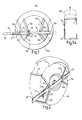
- Figure 1 is a side elevation of a security device according to the invention attached to a vehicle wheel;
- Figure la is an elevation of the same device;
- Figure 2 is an isometric view of a vehicle wheel with the device of Figures 1 and 2 in place so as to prevent rotation of the wheel;
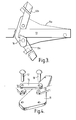
- Figure 3 is an enlarged elevation of a portion of the device shown in Figure 1;
- Figure 4 is an exploded view of parts of the device shown in Figures 1 and 2;
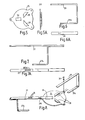
- Figure 5 is an elevation of a boss plate forming part of a second device embodying the invention;
- Figure 5a is an end elevation of the boss plate shown in Figure 5;
- Figure 6 is a plan view of one of a pair of swivelling callipers used in conjunction with the boss plate shown in Figure 5;
- Figure 6a is a front elevation of the same calliper;
- Figure 7 is a plan of a loose calliper or adjustable calliper used with the boss plate of Figure 5;
- Figure 7a is a side elevation of the same loose calliper;
- Figure 8 is an exploded view showing parts of the device ready for assembly;
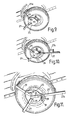
- Figures 9, 10 and 11 show respective stages in the mounting of the device on a vehicle wheel and the locking of the device in place;
- Figure 12 shows another embodiment of the invention in which a security or locking device has a manually operable lever to draw the device tightly onto the wheel or tyre; and
- Figure 13 shows another embodiment of the invention in which the security device is applied to the steering wheel of a motor vehicle.
- In the embodiment of the invention shown in Figures 1 to 4 the security device, which is shown applied to a
wheel 10, comprises afirst boss plate 11 and asecond boss plate 11a. Pivoted to thefirst boss plate 11 are a pair ofcallipers second boss plate 11a are a pair ofcallipers callipers boss plate 11 is illustrated in Figures 3 and 4.Rivets link 16 and through holes in the ends of thecallipers boss plate 11. - This leaves a space between the
link 16 and theboss plate 11 on each of theboss plates 11 and lla. Through this space extends a loose oradjustable calliper 19 which has anextension 20 adapted to engage the ground when the device is applied to a wheel as shown in Figure 2. Theadjustable calliper 19 has a row ofholes 21 which enable the calliper to be locked into position by applying apadlock 22 through one of theholes 21 into a corresponding hole in theboss plate 11. - The remote end of the
loose calliper 19 is curled round at 23 to engage the corresponding end ofboss plate 11a as seen in Figure 2 particularly. - It will be seen that by applying the
pivoted callipers wheel 10 and then pulling theloose calliper 19 tight and locking it in position the security device is firmly attached to the wheel and theextension 20 ofloose calliper 19 prevents the wheel from turning more than a few degrees. - Figure 1 shows the way in which the device is capable of adjustment to accommodate various sizes of wheels. The
wheel 10a is of larger diameter than thewheel 10 but as can be seen from the dotted positions of theboss plates 11, lla and the corresponding positions of the callipers the device may be arranged. to lock a larger diameter wheel, or a smaller diameter wheel as desired. - In the embodiment of the invention shown in Figures 5, to 11 there is only a single boss plate 25 (Figure 5 and 5a). The
boss plate 25 is provided with abracket 26 welded to the boss plate and adapted to receive the adjustable orloose calliper 27. Theboss plate 25 also has twostops 28 which are in the form of short plates welded to the boss plate and act as stops which limit the pivoting movement of a pair ofcallipers 29, only one of which is shown in Figure 8.Callipers 29 are attached toboss plate 25 so as to be free to pivot by means ofrivets 30. - The shape of the
calliper 29 is shown more clearly in Figures 6 and 6a and the shape of thecalliper 27 is shown more clearly in Figures 7 and 7a. It will be seen that thecalliper 29 has anextension 29a adapted to wrap around a wheel so that the calliper can engage both sides of a wheel. Similarlycalliper 27 has anextension 27a to wrap around the wheel. - Calliper 27 also has a row of
holes 28 which are adapted to register with ahole 29b in the end of theboss plate 25. By sliding theadjustable calliper 27 in thebracket 26 and then putting a locking device such as a padlock through registering one ofholes 28 andhole 29b, thecalliper 27 may be locked in position. - This can be illustrated more clearly by reference to Figures 9 to 11. In Figure 9 the device is shown applied to a trailer wheel, the
boss plate 25 and twocallipers 29 are first offered up to the wheel, with one of thecallipers 29 being passed underneath the mud-guard so that theextensions 29a, or returns of the callipers, pass on the far side of the wheel. - As shown in Figure 10 the
loose calliper 27 is then offered up to theboss plate 25 again with theextension 27a passing on the other side of the wheel. - The
loose calliper 27 is then pushed through thebracket 26 at the same time holding theboss plate 25 firmly so that thecallipers 29 engage the wheel. When the whole assembly is tight on the wheel a padlock 31 is placed through one of theholes 28 in theloose calliper 27 and in a hole formed in the end of the boss plate 25 (shown in Figure 8). - Thus the whole device is firmly held on the wheel and if somebody should attempt to move the trailer the
end 27b of the device engages against the ground or against the fixed part of the trailer thus preventing movement of more than a few inches. - The embodiment shown in Figure 12 is different in that although it has a
central boss plate 32 and a pair ofpivoted calliper arms loose calliper arm 35 is changed. The loose calliper arm passes through abracket 36 which performs a number of functions. Firstly it provides a guide for theloose calliper arm 35. Secondly it provides at 36a and 36b the stops for the pivotedcallipers aperture 37 provision for the locking device. The locking device in this instance can be a pushbutton type lock 38 which enters thehole 37 in thebracket 36 and engages theloose calliper 35 so as to lock it in position. - To assist the operator in obtaining a really tight fit onto the wheel or tyre a pivoted
lever 39 is provided, pivoted at 40 onto theboss plate 32. This lever has apin 40a adapted to engage in any one of a number of half round slots ornotches 41 in the lower side of theloose calliper 35. - By engaging the
calliper 35 insuccessive brackets pin 40a of pivotedlever 39 in anappropriate notch 41, the lever can be moved clockwise as seen in Figure 12 so as to draw thecalliper 35 to the right and thus tighten upcallipers press button lock 37 may be applied so as to lock thecalliper 35 in place. - The device as described above may be applied to any type of wheel and to illustrate an alternative application Figure 13 shows a security device embodying the invention applied to a
steering wheel 43 of a motor vehicle. The device includes aboss plate 44, pivotedcalliper arms extension returns steering wheel 43. The pivoting movement of thecallipers plate 48 attached to theboss plate 44. -
Theboss plate 44 also has abracket 49 through which a loose oradjustable calliper 50 extends. Theadjustable calliper 50 has anextension 51 or return portion to engage the rim of the steering wheel and also has a row ofholes 52. - When the device is applied to a steering wheel in a similar manner to that described in relation to a vehicle wheel above, the
adjustable calliper 50 can be locked in place by means of apush button lock 53 which has an extension (not shown) which passes through ahole 52 in theadjustable calliper 50 and into a hole (not shown) in theboss plate 44. - The
outward extension 54 of theadjustable calliper 50 is arranged to engage against a fixed portion of the motor vehicle such as the seat or door, thus preventing the steering wheel being turned. - The lock incorporated in this arrangement is similar to the lock incorporated in the Figure 12 arrangement and is a known integral barrel lock type. It locks the lever by engaging a stud, formed at the end of the barrel in a tongue formed on a locking lever. When the lever has reached the end of its travel the barrel is depressed causing the stud to enter a bole in the tongue..-A pole retains the barrel in this position until the key is inserted and turned to disengage the pole allowing the barrel to pop out. Since this type of lock is well-known it is not illustrated in detail.
- Reverting to the arrangement shown in Figure 11, for example, it will be seen that the
boss plate 25 serves to prevent access to the wheel nuts and is suitably shaped to this end. - In each instance removal of the device is carried out by reversing the sequence described for putting it in position.
- Towable vehicles, whilst uncoupled and unattended, are particularly vulnerable to illicit removal. When fitted and locked up as described above the security device of the invention immobilises the vehicle by preventing rotation of the wheel. Similarly if applied to a steering wheel or other wheel which operates machinery etc., the machinery cannot be operated or the vehicle cannot be steered with the device in position
Claims (12)
Priority Applications (1)
| Application Number | Priority Date | Filing Date | Title |
|---|---|---|---|
| AT82306360T ATE27431T1 (en) | 1981-12-01 | 1982-11-30 | SECURITY DEVICE. |
Applications Claiming Priority (4)
| Application Number | Priority Date | Filing Date | Title |
|---|---|---|---|
| GB8136220 | 1981-12-01 | ||
| GB8136220 | 1981-12-01 | ||
| GB8212767A GB2110175A (en) | 1981-12-01 | 1982-04-30 | Wheeled vehicle theft deterrent |
| GB8212767 | 1982-04-30 |
Publications (2)
| Publication Number | Publication Date |
|---|---|
| EP0080893A1 true EP0080893A1 (en) | 1983-06-08 |
| EP0080893B1 EP0080893B1 (en) | 1987-05-27 |
Family
ID=26281428
Family Applications (1)
| Application Number | Title | Priority Date | Filing Date |
|---|---|---|---|
| EP19820306360 Expired EP0080893B1 (en) | 1981-12-01 | 1982-11-30 | Security device |
Country Status (5)
| Country | Link |
|---|---|
| EP (1) | EP0080893B1 (en) |
| AU (1) | AU562201B2 (en) |
| CA (1) | CA1196791A (en) |
| DE (1) | DE3276417D1 (en) |
| GB (1) | GB2110175A (en) |
Cited By (12)
| Publication number | Priority date | Publication date | Assignee | Title |
|---|---|---|---|---|
| EP0189366A1 (en) * | 1985-01-22 | 1986-07-30 | SHAKBAR INVESTMENTS Ltd. | Motor vehicle accessory particularly useful for protecting the vehicle against theft |
| EP0272801A1 (en) * | 1986-11-25 | 1988-06-29 | Nigel William Richards | Vehicle immobilising device |
| EP0298716A1 (en) * | 1987-07-07 | 1989-01-11 | Leslie Hedges | Wheel clamp |
| FR2660610A1 (en) * | 1989-07-18 | 1991-10-11 | Bedouin Andre | Anti-theft device for car wheels (wheel clamp) |
| GB2271969A (en) * | 1992-10-09 | 1994-05-04 | Graham Cox | Vehicle security wheel clamp |
| WO1994025316A1 (en) * | 1993-04-23 | 1994-11-10 | Andrea Mombelli | Antitheft device for motor vehicles to fit onto a wheel |
| NL9301896A (en) * | 1993-11-03 | 1995-06-01 | Unimeta Nederland B V | Clamping device for a wheel |
| FR2723900A1 (en) * | 1994-08-23 | 1996-03-01 | Lebrun Pierre | Car accessory for anti=theft protection and locking wheel nuts |
| US5836186A (en) * | 1995-10-10 | 1998-11-17 | Winner International Royalty Corporation | Steering wheel protection device |
| US5842361A (en) * | 1993-01-21 | 1998-12-01 | Winner International Royalty Corporation | Vehicle security device |
| CN1906066B (en) * | 2004-05-06 | 2010-09-29 | 约翰·克拉克 | Wheel immobilizer |
| US10895092B2 (en) * | 2019-04-16 | 2021-01-19 | Richard Rapp | Tire anchoring system |
Families Citing this family (25)
| Publication number | Priority date | Publication date | Assignee | Title |
|---|---|---|---|---|
| GB2124566B (en) * | 1982-06-22 | 1985-11-13 | John Robert Tillard | Immobilising vehicles |
| US4768359A (en) * | 1986-07-31 | 1988-09-06 | Wade Mark W | Wheel lock |
| US4723426A (en) * | 1986-12-15 | 1988-02-09 | Fernand Beaudoin | Wheel clamp attachment |
| US4854144A (en) * | 1987-08-17 | 1989-08-08 | Double Helix Enterprises | Vehicle immobilization device |
| US4949561A (en) * | 1989-04-07 | 1990-08-21 | Wolo Manufacturing Corporation | Steering wheel lock bar |
| WO1992004211A1 (en) * | 1990-09-06 | 1992-03-19 | A.B.A. Marketing Pty Limited | Vehicle steering-wheel lock |
| AU645350B2 (en) * | 1990-09-06 | 1994-01-13 | A.B.A. Marketing Pty Limited | Vehicle steering-wheel lock |
| GB2251416B (en) * | 1991-01-05 | 1993-09-22 | Lancashire Clamping Company Li | Wheel clamps |
| GB2260955A (en) * | 1991-10-29 | 1993-05-05 | Philip Denman | Wheel clamps |
| US5284036A (en) * | 1992-12-02 | 1994-02-08 | Rosenbaum Nathan B | Tamper-resistant security lock for cargo container doors |
| GB9303071D0 (en) * | 1993-02-16 | 1993-03-31 | Cestria Fabrications Ltd | Vehicle wheel clamp |
| GB2279632A (en) * | 1993-07-02 | 1995-01-11 | Grayspeed Leisure Products Lim | Wheel clamp |
| US5333477A (en) * | 1993-07-20 | 1994-08-02 | Phillip Davis | Vehicle parking boot |
| US5437171A (en) * | 1993-08-20 | 1995-08-01 | Owen; Joseph L. | Device for preventing free rotation of a wheel of a stationary vehicle |
| GB9400365D0 (en) * | 1994-01-11 | 1994-03-09 | Sedgeman Graham L | Clamping device |
| GB9400860D0 (en) * | 1994-01-18 | 1994-03-16 | Dewman Philip | Wheelclamp |
| US5537847A (en) * | 1994-03-07 | 1996-07-23 | Dalton; Michael | Anti-theft device for motor vehicles |
| US5706682A (en) * | 1994-10-31 | 1998-01-13 | Barker; J. W. | Vehicle safety and security device removably mountable to surround a vehicle tire |
| US5715711A (en) * | 1996-02-08 | 1998-02-10 | Jennison; Thomas | Portable wheel immobilizing device |
| USD383372S (en) | 1996-04-10 | 1997-09-09 | Winner International Royalty Corporation | Steering wheel guard |
| US5855128A (en) * | 1997-09-10 | 1999-01-05 | Winner International Royalty Corporation | Steering wheel protection device |
| US5996721A (en) * | 1998-02-02 | 1999-12-07 | Winner International Royalty Llc | Steering wheel and air bag protection device |
| US6109076A (en) * | 1999-05-06 | 2000-08-29 | Master Lock Company | Automobile and airbag anti-theft device |
| US6125672A (en) * | 2000-03-03 | 2000-10-03 | Diez; Adalberto | Security devices for vehicle |
| DE102022103157B3 (en) | 2022-02-10 | 2023-02-16 | Dr. Ing. H.C. F. Porsche Aktiengesellschaft | Securing arrangement for a vehicle wheel |
Citations (3)
| Publication number | Priority date | Publication date | Assignee | Title |
|---|---|---|---|---|
| DE7735706U1 (en) * | Hartesveldt, Jean-Jacques Van, Aerdenhout (Niederlande) | |||
| US1502933A (en) * | 1923-08-22 | 1924-07-29 | John M Allen | Auto lock |
| GB1269813A (en) * | 1968-04-16 | 1972-04-06 | Stayput Engineering Pty Ltd | A motor vehicle anti-theft device |
-
1982
- 1982-04-30 GB GB8212767A patent/GB2110175A/en not_active Withdrawn
- 1982-11-30 CA CA000416707A patent/CA1196791A/en not_active Expired
- 1982-11-30 EP EP19820306360 patent/EP0080893B1/en not_active Expired
- 1982-11-30 DE DE8282306360T patent/DE3276417D1/en not_active Expired
- 1982-12-01 AU AU91036/82A patent/AU562201B2/en not_active Ceased
Patent Citations (3)
| Publication number | Priority date | Publication date | Assignee | Title |
|---|---|---|---|---|
| DE7735706U1 (en) * | Hartesveldt, Jean-Jacques Van, Aerdenhout (Niederlande) | |||
| US1502933A (en) * | 1923-08-22 | 1924-07-29 | John M Allen | Auto lock |
| GB1269813A (en) * | 1968-04-16 | 1972-04-06 | Stayput Engineering Pty Ltd | A motor vehicle anti-theft device |
Cited By (13)
| Publication number | Priority date | Publication date | Assignee | Title |
|---|---|---|---|---|
| US4651849A (en) * | 1985-01-22 | 1987-03-24 | Shakbar Investments Ltd. | Motor vehicle accessory particularly useful for protecting the vehicle against theft |
| EP0189366A1 (en) * | 1985-01-22 | 1986-07-30 | SHAKBAR INVESTMENTS Ltd. | Motor vehicle accessory particularly useful for protecting the vehicle against theft |
| EP0272801A1 (en) * | 1986-11-25 | 1988-06-29 | Nigel William Richards | Vehicle immobilising device |
| EP0298716A1 (en) * | 1987-07-07 | 1989-01-11 | Leslie Hedges | Wheel clamp |
| FR2660610A1 (en) * | 1989-07-18 | 1991-10-11 | Bedouin Andre | Anti-theft device for car wheels (wheel clamp) |
| GB2271969A (en) * | 1992-10-09 | 1994-05-04 | Graham Cox | Vehicle security wheel clamp |
| US5842361A (en) * | 1993-01-21 | 1998-12-01 | Winner International Royalty Corporation | Vehicle security device |
| WO1994025316A1 (en) * | 1993-04-23 | 1994-11-10 | Andrea Mombelli | Antitheft device for motor vehicles to fit onto a wheel |
| NL9301896A (en) * | 1993-11-03 | 1995-06-01 | Unimeta Nederland B V | Clamping device for a wheel |
| FR2723900A1 (en) * | 1994-08-23 | 1996-03-01 | Lebrun Pierre | Car accessory for anti=theft protection and locking wheel nuts |
| US5836186A (en) * | 1995-10-10 | 1998-11-17 | Winner International Royalty Corporation | Steering wheel protection device |
| CN1906066B (en) * | 2004-05-06 | 2010-09-29 | 约翰·克拉克 | Wheel immobilizer |
| US10895092B2 (en) * | 2019-04-16 | 2021-01-19 | Richard Rapp | Tire anchoring system |
Also Published As
| Publication number | Publication date |
|---|---|
| AU9103682A (en) | 1983-06-09 |
| DE3276417D1 (en) | 1987-07-02 |
| EP0080893B1 (en) | 1987-05-27 |
| AU562201B2 (en) | 1987-06-04 |
| GB2110175A (en) | 1983-06-15 |
| CA1196791A (en) | 1985-11-19 |
Similar Documents
| Publication | Publication Date | Title |
|---|---|---|
| EP0080893A1 (en) | Security device | |
| KR930000288B1 (en) | Steering wheel lock | |
| US4003228A (en) | Security apparatus for vehicle communications accessory | |
| US4033160A (en) | Bicycle lock | |
| US4526021A (en) | Spare tire lock | |
| US5375442A (en) | Clamp assembly for a trailer or like wheeled vehicle | |
| US4164131A (en) | Automobile anti-theft device | |
| US5044845A (en) | Snowmobile transport apparatus | |
| US5547045A (en) | Adjustable wheel chocks for tandem wheeled vehicles | |
| US6824121B2 (en) | Wheel securing device | |
| US6918466B1 (en) | Lockable brake pedal fastener | |
| US4175410A (en) | Vehicle wheel engageable blocking device | |
| US5823022A (en) | Tailgate lock | |
| US6705137B2 (en) | Lock device for semitrailers and the like | |
| US3713668A (en) | Protective device for trailers and like vehicles | |
| EP0775064B1 (en) | Automobile security device | |
| US5000067A (en) | Lock for trailer hitch | |
| US4013203A (en) | Lockable tire carrier | |
| US5778709A (en) | Vehicle steering wheel and air bag antitheft locking apparatus | |
| US4977974A (en) | Locking device for automobiles | |
| US5263553A (en) | Wheel immobilizing apparatus with spacing and latching mechanisms for accommodating different wheel sizes | |
| US4750341A (en) | Vehicle anti-theft device | |
| US4958870A (en) | Combination bumper and tire storage compartment with tire lock mechanism | |
| US20030106352A1 (en) | Column lock device | |
| WO1986005150A1 (en) | A vehicle road wheel locking device |
Legal Events
| Date | Code | Title | Description |
|---|---|---|---|
| PUAI | Public reference made under article 153(3) epc to a published international application that has entered the european phase |
Free format text: ORIGINAL CODE: 0009012 |
|
| AK | Designated contracting states |
Designated state(s): AT BE CH DE FR GB IT LI LU NL SE |
|
| 17P | Request for examination filed |
Effective date: 19831206 |
|
| 17Q | First examination report despatched |
Effective date: 19851001 |
|
| GRAA | (expected) grant |
Free format text: ORIGINAL CODE: 0009210 |
|
| AK | Designated contracting states |
Kind code of ref document: B1 Designated state(s): AT BE CH DE FR GB IT LI LU NL SE |
|
| PG25 | Lapsed in a contracting state [announced via postgrant information from national office to epo] |
Ref country code: AT Effective date: 19870527 |
|
| REF | Corresponds to: |
Ref document number: 27431 Country of ref document: AT Date of ref document: 19870615 Kind code of ref document: T |
|
| PG25 | Lapsed in a contracting state [announced via postgrant information from national office to epo] |
Ref country code: SE Effective date: 19870531 |
|
| REF | Corresponds to: |
Ref document number: 3276417 Country of ref document: DE Date of ref document: 19870702 |
|
| ITF | It: translation for a ep patent filed |
Owner name: STUDIO TORTA SOCIETA' SEMPLICE |
|
| ET | Fr: translation filed | ||
| PG25 | Lapsed in a contracting state [announced via postgrant information from national office to epo] |
Ref country code: LU Free format text: LAPSE BECAUSE OF NON-PAYMENT OF DUE FEES Effective date: 19871130 |
|
| PGFP | Annual fee paid to national office [announced via postgrant information from national office to epo] |
Ref country code: NL Payment date: 19871130 Year of fee payment: 6 |
|
| PLBE | No opposition filed within time limit |
Free format text: ORIGINAL CODE: 0009261 |
|
| STAA | Information on the status of an ep patent application or granted ep patent |
Free format text: STATUS: NO OPPOSITION FILED WITHIN TIME LIMIT |
|
| 26N | No opposition filed | ||
| PG25 | Lapsed in a contracting state [announced via postgrant information from national office to epo] |
Ref country code: LI Effective date: 19881130 Ref country code: CH Effective date: 19881130 Ref country code: BE Effective date: 19881130 |
|
| PGFP | Annual fee paid to national office [announced via postgrant information from national office to epo] |
Ref country code: FR Payment date: 19890523 Year of fee payment: 7 Ref country code: DE Payment date: 19890523 Year of fee payment: 7 |
|
| BERE | Be: lapsed |
Owner name: ARTPACK LTD Effective date: 19881130 |
|
| PGFP | Annual fee paid to national office [announced via postgrant information from national office to epo] |
Ref country code: GB Payment date: 19890531 Year of fee payment: 7 |
|
| PG25 | Lapsed in a contracting state [announced via postgrant information from national office to epo] |
Ref country code: NL Effective date: 19890601 |
|
| NLV4 | Nl: lapsed or anulled due to non-payment of the annual fee | ||
| REG | Reference to a national code |
Ref country code: CH Ref legal event code: PL |
|
| ITTA | It: last paid annual fee | ||
| PG25 | Lapsed in a contracting state [announced via postgrant information from national office to epo] |
Ref country code: GB Effective date: 19891130 |
|
| GBPC | Gb: european patent ceased through non-payment of renewal fee | ||
| PG25 | Lapsed in a contracting state [announced via postgrant information from national office to epo] |
Ref country code: FR Effective date: 19900731 |
|
| PG25 | Lapsed in a contracting state [announced via postgrant information from national office to epo] |
Ref country code: DE Effective date: 19900801 |
|
| REG | Reference to a national code |
Ref country code: FR Ref legal event code: ST |