EP0080487B1 - Covering panel for roofs and outside walls of buildings - Google Patents
Covering panel for roofs and outside walls of buildings Download PDFInfo
- Publication number
- EP0080487B1 EP0080487B1 EP19820901795 EP82901795A EP0080487B1 EP 0080487 B1 EP0080487 B1 EP 0080487B1 EP 19820901795 EP19820901795 EP 19820901795 EP 82901795 A EP82901795 A EP 82901795A EP 0080487 B1 EP0080487 B1 EP 0080487B1
- Authority
- EP
- European Patent Office
- Prior art keywords
- corrugation
- panel
- gap
- flange
- panels
- Prior art date
- Legal status (The legal status is an assumption and is not a legal conclusion. Google has not performed a legal analysis and makes no representation as to the accuracy of the status listed.)
- Expired
Links
- 238000007664 blowing Methods 0.000 claims abstract description 7
- XLYOFNOQVPJJNP-UHFFFAOYSA-N water Substances O XLYOFNOQVPJJNP-UHFFFAOYSA-N 0.000 abstract description 10
- 230000035515 penetration Effects 0.000 abstract description 4
- 238000004519 manufacturing process Methods 0.000 description 4
- 230000000994 depressogenic effect Effects 0.000 description 2
- 230000000149 penetrating effect Effects 0.000 description 2
- 238000005452 bending Methods 0.000 description 1
- 230000007423 decrease Effects 0.000 description 1
- 230000000694 effects Effects 0.000 description 1
- 239000000463 material Substances 0.000 description 1
- 238000012986 modification Methods 0.000 description 1
- 230000004048 modification Effects 0.000 description 1
Images
Classifications
-
- E—FIXED CONSTRUCTIONS
- E04—BUILDING
- E04D—ROOF COVERINGS; SKY-LIGHTS; GUTTERS; ROOF-WORKING TOOLS
- E04D3/00—Roof covering by making use of flat or curved slabs or stiff sheets
- E04D3/24—Roof covering by making use of flat or curved slabs or stiff sheets with special cross-section, e.g. with corrugations on both sides, with ribs, flanges, or the like
- E04D3/30—Roof covering by making use of flat or curved slabs or stiff sheets with special cross-section, e.g. with corrugations on both sides, with ribs, flanges, or the like of metal
Definitions
- the present invention relates to a covering panel for roofs and the outside walls of buildings.
- the separate panels When covering a roof or wall with panels, such as corrugated panels, the separate panels are positioned with the side edges overlapping each other, so that one corrugation adjacent the leading edge of one panel is positioned over a corrugation at the trailing edge of a preceding panel.
- a narrow gap or slot may be defined between the panels, and when rain is falling water can penetrate through this gap or slot by capillary suction.
- the penetration of water increases due to the creation of a partial vacuum under the covering panels as the result of the action of the wind.
- Such penetration of water can cause serious damage, giving rise to damp, and thus it is frequently necessary to provide a separate layer of waterproof material, underneath a roof or wall covering of the type described above, to provide adequate protection against leaking water.
- conduits for draining any water that may penetrate between overlapped panels in the region of the overlaps see e.g. SE 381 075.
- the provision of such conduits will make the manufacture and mounting of the panels more complicated, and thus more expensive.
- US-A-879 708 discloses a sinusoidal corrugated panel, and a panel having two triangular corrugations, one adjacent each longitudinal edge.
- the specification describes a joint between two corresponding panels, and in each case the final flange of the upper corrugation of the overlapping joint is spaced from the corresponding flange of the corrugation of the lower panel, and the free edge of said final flange touches the upper surface of the lower panel.
- the present invention seeks to provide a covering panel having an edge portion which can be overlapped with the opposite edge portion of a corresponding covering panel to provide a joint which prevents leakage between the panels, the panel nevertheless being simple to manufacture.
- a covering panel for covering a roof or the outside wall of a building, said covering panel comprising at least two projecting corrugations, one extending along each of two longitudinal edges of the panel, the free flange of one of these corrugations being provided with a bent region extending continuously in the longitudinal direction of the corrugation, the bent region being such that a portion of the free flanges is spaced away from the underlying corrugation of a corresponding panel, when the said one corrugation is located over the corrugation provided at the opposite longitudinal edge of the corresponding panel to create an overlapped joint, a gap or chamber being created with such a large width that no capillary forces can arise between the walls of the gap and the free edge of the free flange of the said one corrugation of the upper panel being situated at a point which is spaced from the underlying flange of the underlying corrugation, wherein the free edge of the free flange is spaced sufficiently from the base of the underlying corrugation to define an open mouth which is
- the free edge of the flange is situated at a distance below the upper level of the said one corrugation which is smaller than half the height (h) of the corrugation.
- the said bent region is provided immediately below the upper level of the said one corrugation.
- the gap or chamber has a width of at least 4 millimetres, and preferably 5-10 millimetres.
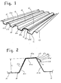
- FIG 1 illustrates two identical covering panels 10, 11 which are each corrugated.
- the panels define longitudinal corrugations or ribs, panel 10 defining corrugations or ribs 12-15 and panel 11 defining corrugations or ribs 16-17 respectively.
- Each corrugation or rib has a trapezoidal cross-section, and thus each corrugation or rib comprises a top section 13a, and flange sections 13b, 13c on either side of the top section.
- Each panel is illustrated as being provided with a plurality of corrugations, but the most important corrugations are the corrugations adjacent each longitudinal edge of the panel.
- the flange 15c that forms part of the outermost corrugation 15 of the first panel, and which also serves to define the free edge of the upper panel 10 is provided with a bent region 15d, which is more clearly illustrated in Figure 2. It is to be noted that the panels are located with a single overlap, that is to say one corrugation of the upper panel 10 overlaps only one corrugation of the lower panel.
- the corrugation 16 of the lower panel 11 has a planar top portion 16a, and planar flange portions 16b, 16c.
- the flange 16c is provided with a curved or bent terminal edge region 18 which defines the edge of the panel, and lies under the trough defined between the corrugation 15 and the adjacent corrugation 14 in the upper panel 10.
- the corrugation 15 of the upper panel 10 has a planar top portion 15a and two flange portions 15b, 15c, with the flange portion 15c serving to define the edge of the panel.
- the flange 15c does not engage or cover the whole of the flange 16b of the corrugation 16 of the lower panel, but terminates at a point above the middle of the flange 16b, the point being spaced away from the flange 16b.
- the vertical distance between the free edge of the outer flange 15c of the corrugation of the upper panel, and the uppermost level of the upper panel is less than half the height h of each corrugation present in the upper panel.
- the free flange 15c is provided with a bent region 15d that extends continuously in the longitudinal direction of the corrugation over the entire longitudinal length of the panel.
- the bent region includes two parallel folds 20, 21, the first being outward fold and the second being a downward fold.
- the lower terminal region of the flange 15c is displaced from, but parallel to, the plane of the uppermost region of the flange 15c. Consequently a gap or chamber 22 is established between the terminal portion of a flange 15c and the underlying flange 16b of the corrugation 16 of the lower sheet 11.
- the gap or chamber 22 is open downwardly towards the lower panel, and has an open mouth illustrated as having a width b. Thus no capillary forces can arise within this gap or chamber.
- the gap or chamber forms a chamber of turbulence in which a partial vacuum arises when the wind is blowing. This partial vacuum tends to balance the partial vacuum that arises under the panels when the wind is blowing thus preventing water from penetrating between the panels and running away under the panels.
- the turbulence that arises in the gap when the wind blows further decreases the risk of water penetrating between the panels in the region of the overlap.
- the gap or chamber should preferably have a width at least 4 millimetres, and most advantageously at least 5 millimetres, e.g. 5-10 millimetres.
- This specified width of the gap refers to the perpendicular distance between the terminal portion of the upper flange of the corrugation of the upper sheet and the corresponding flange of the corrugation of the lower sheet.
- the bent region 15d on the free flange 15c is preferably arranged immediately below the upper level of the corresponding corrugation, so that the upper portion of the gap or chamber 22 is connected to an air channel 23 formed between the panels in the region of the upper edges of the flanges 15c, 15d, due to the difference between the inner radius and the outer radius of the corrugations.
- the distance between the folds 20, 21, can preferably be in the region of 8-9 millimetres, and the portion between the folds 20, 21 can lie at an angle of approximately 45° to the plane occupied by the uppermost region and the lower terminal region of the free flange 15c.
- the distance from the lower fold 21 to the lower free edge of the flange 16c can preferably be about 6 millimetres.
- Embodiments of the invention incorpoarate at least two corrugations, that is to say one corrugation along each of two opposite longitudinal edges of the panel. It is to be understood that the details of the design of the panel between these two corrugations is not important, as far as the present invention is concerned.
- the corrugations need not necessarily have a trapezoidal cross-section but it can alternatively have a wave-like or square cross-section.
- the bent region in the free flange of the final corrugation of the upper sheet need not necessarily be created by folding the free flange, but can alternatively be created by providing a soft bending of the flange. It is possible to use a combination of a fold and a soft bend.
- the free flange, at its edge opens, into a space or chamber in which a partial vacuum arises when the wind is blowing, so that the partial vacuum created under the panels by the wind is balanced or compensated.
- the described gap or chamber can alternatively be positioned lower, that is to say closer to the bottom portion of the corrugations than illustrated in the accompanying drawings and described above.
Landscapes
- Engineering & Computer Science (AREA)
- Architecture (AREA)
- Civil Engineering (AREA)
- Structural Engineering (AREA)
- Building Environments (AREA)
- Roof Covering Using Slabs Or Stiff Sheets (AREA)
Abstract
Description
- The present invention relates to a covering panel for roofs and the outside walls of buildings.
- It has been proposed to provide various covering panels for use in covering the roof or outside wall of a building, and many such covering panels are provided with corrugations at least adjacent two opposite longitudinal edges of the panel.
- When covering a roof or wall with panels, such as corrugated panels, the separate panels are positioned with the side edges overlapping each other, so that one corrugation adjacent the leading edge of one panel is positioned over a corrugation at the trailing edge of a preceding panel. However, in this overlap region a narrow gap or slot may be defined between the panels, and when rain is falling water can penetrate through this gap or slot by capillary suction. When the wind is blowing it is often found that the penetration of water increases due to the creation of a partial vacuum under the covering panels as the result of the action of the wind. Such penetration of water can cause serious damage, giving rise to damp, and thus it is frequently necessary to provide a separate layer of waterproof material, underneath a roof or wall covering of the type described above, to provide adequate protection against leaking water.
- Attempts have been made to prevent leakage by securing the panels as tightly as possible to each other in the overlapping regions, in an attempt to eradicate the gap or slot between the panels. However, it has not been found to be possible to provide water tight overlaps at a reasonable price, due to manufacturing tolerances.
- It has been proposed to provide conduits for draining any water that may penetrate between overlapped panels in the region of the overlaps, see e.g. SE 381 075. The provision of such conduits, however, will make the manufacture and mounting of the panels more complicated, and thus more expensive.
- It has also been proposed to provide a corrugation, adjacent the edge of a panel, which is provided with a depressed groove on the exterior flange of the corrugation. See for example, AU 255 261. Such a groove leads to the creation of a space between the panels in the region of the overlap, and no capillary action can operate within the space. Whilst the provision of such a space tends to eliminate the capillary forces in a region of the overlap, it does not totally prevent penetration of water between the panels due to the partial vacuum created under the panels when the wind blows. Also, from a manufacturing point of view, it is relatively difficult to provide such a depressed groove on the final flange of a corrugation.
- US-A-879 708 discloses a sinusoidal corrugated panel, and a panel having two triangular corrugations, one adjacent each longitudinal edge. The specification describes a joint between two corresponding panels, and in each case the final flange of the upper corrugation of the overlapping joint is spaced from the corresponding flange of the corrugation of the lower panel, and the free edge of said final flange touches the upper surface of the lower panel. Even with a joint of this nature, whilst the capillary action may be defeated, moisture may still penetrate the overlapping joint when a partial vacuum is created beneath the panels due to the effect of the wind.
- The present invention seeks to provide a covering panel having an edge portion which can be overlapped with the opposite edge portion of a corresponding covering panel to provide a joint which prevents leakage between the panels, the panel nevertheless being simple to manufacture.
- According to this invention there is provided a covering panel for covering a roof or the outside wall of a building, said covering panel comprising at least two projecting corrugations, one extending along each of two longitudinal edges of the panel, the free flange of one of these corrugations being provided with a bent region extending continuously in the longitudinal direction of the corrugation, the bent region being such that a portion of the free flanges is spaced away from the underlying corrugation of a corresponding panel, when the said one corrugation is located over the corrugation provided at the opposite longitudinal edge of the corresponding panel to create an overlapped joint, a gap or chamber being created with such a large width that no capillary forces can arise between the walls of the gap and the free edge of the free flange of the said one corrugation of the upper panel being situated at a point which is spaced from the underlying flange of the underlying corrugation, wherein the free edge of the free flange is spaced sufficiently from the base of the underlying corrugation to define an open mouth which is open towards the lower panel, so that a partial vacuum arises within the resultant gap or chamber when the wind is blowing.
- Preferably the free edge of the flange is situated at a distance below the upper level of the said one corrugation which is smaller than half the height (h) of the corrugation.
- Conveniently the said bent region is provided immediately below the upper level of the said one corrugation.
- Advantageously the gap or chamber has a width of at least 4 millimetres, and preferably 5-10 millimetres.
- In order that the invention may be more readily understood, and so that further features thereof may be appreciated, the invention will now be described by way of example with reference to the accompanying drawings, in which:
- Figure 1 is a perspective view of portions of two corrugated covering panels in accordance with the invention with overlapping edges; and
- Figure 2 is a cross-section on an enlarged scale through the region of the overlap.
- Figure 1 illustrates two
identical covering panels 10, 11 which are each corrugated. The panels define longitudinal corrugations or ribs,panel 10 defining corrugations or ribs 12-15 and panel 11 defining corrugations or ribs 16-17 respectively. Each corrugation or rib has a trapezoidal cross-section, and thus each corrugation or rib comprises a top section 13a, and flange sections 13b, 13c on either side of the top section. - Each panel is illustrated as being provided with a plurality of corrugations, but the most important corrugations are the corrugations adjacent each longitudinal edge of the panel.
- In Figure 1 only portions of the two
panels 10, 11 are illustrated, one flange 15 adjacent the leading edge of thepanel 10 being illustrated overlapping the trailing edge of the other panel 11. - The flange 15c that forms part of the outermost corrugation 15 of the first panel, and which also serves to define the free edge of the
upper panel 10 is provided with a bent region 15d, which is more clearly illustrated in Figure 2. It is to be noted that the panels are located with a single overlap, that is to say one corrugation of theupper panel 10 overlaps only one corrugation of the lower panel. - Referring to Figure 2, the overlapping portions of the panels are shown on an enlarged scale. The
corrugation 16 of the lower panel 11 has a planar top portion 16a, and planar flange portions 16b, 16c. The flange 16c is provided with a curved or bentterminal edge region 18 which defines the edge of the panel, and lies under the trough defined between the corrugation 15 and theadjacent corrugation 14 in theupper panel 10. - The corrugation 15 of the
upper panel 10 has a planartop portion 15a and two flange portions 15b, 15c, with the flange portion 15c serving to define the edge of the panel. The flange 15c does not engage or cover the whole of the flange 16b of thecorrugation 16 of the lower panel, but terminates at a point above the middle of the flange 16b, the point being spaced away from the flange 16b. - The vertical distance between the free edge of the outer flange 15c of the corrugation of the upper panel, and the uppermost level of the upper panel is less than half the height h of each corrugation present in the upper panel.
- The free flange 15c is provided with a bent region 15d that extends continuously in the longitudinal direction of the corrugation over the entire longitudinal length of the panel. The bent region includes two
parallel folds chamber 22 is established between the terminal portion of a flange 15c and the underlying flange 16b of thecorrugation 16 of the lower sheet 11. The gap orchamber 22 is open downwardly towards the lower panel, and has an open mouth illustrated as having a width b. Thus no capillary forces can arise within this gap or chamber. - The gap or chamber forms a chamber of turbulence in which a partial vacuum arises when the wind is blowing. This partial vacuum tends to balance the partial vacuum that arises under the panels when the wind is blowing thus preventing water from penetrating between the panels and running away under the panels.
- The turbulence that arises in the gap when the wind blows further decreases the risk of water penetrating between the panels in the region of the overlap.
- To obtain the desired function of the gap or
chamber 22, it has been found that the gap or chamber should preferably have a width at least 4 millimetres, and most advantageously at least 5 millimetres, e.g. 5-10 millimetres. This specified width of the gap refers to the perpendicular distance between the terminal portion of the upper flange of the corrugation of the upper sheet and the corresponding flange of the corrugation of the lower sheet. - The bent region 15d on the free flange 15c is preferably arranged immediately below the upper level of the corresponding corrugation, so that the upper portion of the gap or
chamber 22 is connected to anair channel 23 formed between the panels in the region of the upper edges of the flanges 15c, 15d, due to the difference between the inner radius and the outer radius of the corrugations. - The distance between the
folds folds lower fold 21 to the lower free edge of the flange 16c can preferably be about 6 millimetres. - Whilst only one embodiment of a panel in accordance with the invention has been illustrated and described, it is clear that many variations of modifications are possible within the scope of the invention as defined by the following claims.
- Embodiments of the invention incorpoarate at least two corrugations, that is to say one corrugation along each of two opposite longitudinal edges of the panel. It is to be understood that the details of the design of the panel between these two corrugations is not important, as far as the present invention is concerned. The corrugations need not necessarily have a trapezoidal cross-section but it can alternatively have a wave-like or square cross-section.
- The bent region in the free flange of the final corrugation of the upper sheet need not necessarily be created by folding the free flange, but can alternatively be created by providing a soft bending of the flange. It is possible to use a combination of a fold and a soft bend.
- It is not essential for the walls of the gap or
chamber 22 to be parallel, but it is important that the free flange, at its edge, opens, into a space or chamber in which a partial vacuum arises when the wind is blowing, so that the partial vacuum created under the panels by the wind is balanced or compensated. The described gap or chamber can alternatively be positioned lower, that is to say closer to the bottom portion of the corrugations than illustrated in the accompanying drawings and described above.
Claims (5)
Priority Applications (1)
| Application Number | Priority Date | Filing Date | Title |
|---|---|---|---|
| AT82901795T ATE16032T1 (en) | 1981-06-05 | 1982-06-04 | PANEL FOR ROOFS AND EXTERIOR WALLS OF BUILDINGS. |
Applications Claiming Priority (2)
| Application Number | Priority Date | Filing Date | Title |
|---|---|---|---|
| SE8103543 | 1981-06-05 | ||
| SE8103543A SE452898B (en) | 1981-06-05 | 1981-06-05 | CHARTS FOR COVERING SURFACES AND SURFACES OF BUILDINGS |
Publications (2)
| Publication Number | Publication Date |
|---|---|
| EP0080487A1 EP0080487A1 (en) | 1983-06-08 |
| EP0080487B1 true EP0080487B1 (en) | 1985-10-09 |
Family
ID=20344002
Family Applications (1)
| Application Number | Title | Priority Date | Filing Date |
|---|---|---|---|
| EP19820901795 Expired EP0080487B1 (en) | 1981-06-05 | 1982-06-04 | Covering panel for roofs and outside walls of buildings |
Country Status (4)
| Country | Link |
|---|---|
| EP (1) | EP0080487B1 (en) |
| DE (1) | DE3266779D1 (en) |
| SE (1) | SE452898B (en) |
| WO (1) | WO1982004277A1 (en) |
Families Citing this family (6)
| Publication number | Priority date | Publication date | Assignee | Title |
|---|---|---|---|---|
| ZA832689B (en) * | 1983-03-29 | 1984-01-25 | Wilfried Josef Schenach | Roof cladding |
| FR2649148A1 (en) * | 1989-06-30 | 1991-01-04 | Soretole | Profiled sheet metal element |
| DE4000955C2 (en) * | 1990-01-16 | 2002-01-10 | Aluform System Technik Pohl Gm | Light element for foamed polyurethane roof elements |
| ES2184534B1 (en) * | 1999-06-29 | 2004-08-01 | Juan Jose Bayo Maicas | HERMETIC SOLAPE SYSTEM FOR TRAPEZOID LAYERS OF ROOFS AND FACADES. |
| FR2951529B1 (en) | 2009-10-20 | 2012-05-25 | Philippe Baup | SUPPORT OF PHOTOVOLTAIC MODULES ON ROOFS OR CLADDING. |
| FR2969190B1 (en) * | 2010-12-21 | 2013-02-01 | Sps Pose Soleil | COVERING ELEMENT INTEGRATING A PHOTOVOLTAIC PANEL AND A MOUNTING STRUCTURE. |
Family Cites Families (5)
| Publication number | Priority date | Publication date | Assignee | Title |
|---|---|---|---|---|
| US879708A (en) * | 1907-01-29 | 1908-02-18 | Ellsworth G Welch | Lap-joint for roofing or siding sheets. |
| US1123921A (en) * | 1913-08-25 | 1915-01-05 | Edwin R Probert | Sheet-metal roofing. |
| US1459855A (en) * | 1920-11-30 | 1923-06-26 | Olden Harry Louis | Sheet-metal roofing |
| US2163840A (en) * | 1938-06-03 | 1939-06-27 | Reeves Steel And Mfg Company | Sheet metal roofing |
| US3520100A (en) * | 1968-08-12 | 1970-07-14 | Dixisteel Buildings Inc | Rigid interlocking overlapping panel joint with a drain groove |
-
1981
- 1981-06-05 SE SE8103543A patent/SE452898B/en not_active IP Right Cessation
-
1982
- 1982-06-04 EP EP19820901795 patent/EP0080487B1/en not_active Expired
- 1982-06-04 DE DE8282901795T patent/DE3266779D1/en not_active Expired
- 1982-06-04 WO PCT/SE1982/000198 patent/WO1982004277A1/en not_active Ceased
Also Published As
| Publication number | Publication date |
|---|---|
| DE3266779D1 (en) | 1985-11-14 |
| WO1982004277A1 (en) | 1982-12-09 |
| SE8103543L (en) | 1982-12-06 |
| EP0080487A1 (en) | 1983-06-08 |
| SE452898B (en) | 1987-12-21 |
Similar Documents
| Publication | Publication Date | Title |
|---|---|---|
| US4621466A (en) | Flashing frame for the installation of adjacent roof windows | |
| US4090435A (en) | Ventilators | |
| US4010590A (en) | Metal roof shingle | |
| US3412517A (en) | Shingle | |
| EP3966401B1 (en) | Flashing assembly for a roof penetrating structure and a method for manufacturing a flashing assembly | |
| SU1586524A3 (en) | Roofing panel | |
| EP3404162B1 (en) | A roof window installed in an inclined roof structure with a flashing assembly and a method for weather proofing a roof window | |
| US3828494A (en) | Roof jack | |
| EP0756659B1 (en) | A flashing for roof elements | |
| US3381426A (en) | Metal roofing structure | |
| US4685256A (en) | Connection between the lower edge of a skylight and the adjacent roof covering | |
| EP0397278A1 (en) | Panel | |
| US4138935A (en) | Ventilator | |
| US2641340A (en) | Flashing for corrugated buildings | |
| WO1982004277A1 (en) | Covering panel for roofs and outside walls of buildings | |
| GB2054697A (en) | Roof lining arrangement | |
| EP3404161B1 (en) | A flashing assembly and a method for weather proofing a roof window mounted in an inclined roof surface | |
| EP4026960A1 (en) | A bottom flashing element for a roof penetrating structure, a flashing assembly, and a roof window mounted in an inclined roof | |
| JP7064370B2 (en) | Roof structure | |
| GB1602718A (en) | Roof seal | |
| EP2473686A1 (en) | Device for leading a pipe having a large cross section through a roof | |
| JPH069175Y2 (en) | Exterior metal panel | |
| EP0404814B1 (en) | Roofing sheet | |
| JPH0464650A (en) | Roof structure for building | |
| JP2505206Y2 (en) | Roof structure |
Legal Events
| Date | Code | Title | Description |
|---|---|---|---|
| PUAI | Public reference made under article 153(3) epc to a published international application that has entered the european phase |
Free format text: ORIGINAL CODE: 0009012 |
|
| 17P | Request for examination filed |
Effective date: 19830228 |
|
| AK | Designated contracting states |
Designated state(s): AT BE CH DE FR GB LI LU NL SE |
|
| GRAA | (expected) grant |
Free format text: ORIGINAL CODE: 0009210 |
|
| AK | Designated contracting states |
Designated state(s): AT BE CH DE FR GB LI LU NL SE |
|
| PG25 | Lapsed in a contracting state [announced via postgrant information from national office to epo] |
Ref country code: FR Free format text: THE PATENT HAS BEEN ANNULLED BY A DECISION OF A NATIONAL AUTHORITY Effective date: 19851009 Ref country code: LI Effective date: 19851009 Ref country code: NL Effective date: 19851009 Ref country code: CH Effective date: 19851009 Ref country code: BE Effective date: 19851009 Ref country code: AT Effective date: 19851009 |
|
| REF | Corresponds to: |
Ref document number: 16032 Country of ref document: AT Date of ref document: 19851015 Kind code of ref document: T |
|
| PG25 | Lapsed in a contracting state [announced via postgrant information from national office to epo] |
Ref country code: SE Effective date: 19851030 |
|
| REF | Corresponds to: |
Ref document number: 3266779 Country of ref document: DE Date of ref document: 19851114 |
|
| REG | Reference to a national code |
Ref country code: CH Ref legal event code: PL |
|
| EN | Fr: translation not filed | ||
| NLV1 | Nl: lapsed or annulled due to failure to fulfill the requirements of art. 29p and 29m of the patents act | ||
| PG25 | Lapsed in a contracting state [announced via postgrant information from national office to epo] |
Ref country code: LU Free format text: LAPSE BECAUSE OF NON-PAYMENT OF DUE FEES Effective date: 19860630 |
|
| PLBE | No opposition filed within time limit |
Free format text: ORIGINAL CODE: 0009261 |
|
| STAA | Information on the status of an ep patent application or granted ep patent |
Free format text: STATUS: NO OPPOSITION FILED WITHIN TIME LIMIT |
|
| 26N | No opposition filed | ||
| PGFP | Annual fee paid to national office [announced via postgrant information from national office to epo] |
Ref country code: GB Payment date: 19890731 Year of fee payment: 8 |
|
| PGFP | Annual fee paid to national office [announced via postgrant information from national office to epo] |
Ref country code: DE Payment date: 19890831 Year of fee payment: 8 |
|
| PG25 | Lapsed in a contracting state [announced via postgrant information from national office to epo] |
Ref country code: GB Effective date: 19900604 |
|
| GBPC | Gb: european patent ceased through non-payment of renewal fee | ||
| PG25 | Lapsed in a contracting state [announced via postgrant information from national office to epo] |
Ref country code: DE Effective date: 19910301 |