EP0080447A2 - Means for controlling the position and location of a stationary member acting on the paper web in a paper machine - Google Patents
Means for controlling the position and location of a stationary member acting on the paper web in a paper machine Download PDFInfo
- Publication number
- EP0080447A2 EP0080447A2 EP82850230A EP82850230A EP0080447A2 EP 0080447 A2 EP0080447 A2 EP 0080447A2 EP 82850230 A EP82850230 A EP 82850230A EP 82850230 A EP82850230 A EP 82850230A EP 0080447 A2 EP0080447 A2 EP 0080447A2
- Authority
- EP
- European Patent Office
- Prior art keywords
- slide
- slide member
- web
- control means
- members
- Prior art date
- Legal status (The legal status is an assumption and is not a legal conclusion. Google has not performed a legal analysis and makes no representation as to the accuracy of the status listed.)
- Granted
Links
Images


Classifications
-
- D—TEXTILES; PAPER
- D21—PAPER-MAKING; PRODUCTION OF CELLULOSE
- D21F—PAPER-MAKING MACHINES; METHODS OF PRODUCING PAPER THEREON
- D21F1/00—Wet end of machines for making continuous webs of paper
- D21F1/48—Suction apparatus
- D21F1/483—Drainage foils and bars
- D21F1/486—Drainage foils and bars adjustable
Definitions
- the present invention concerns a means for controlling the position and location of a stationary member, used in a paper machine, acting on the web that is being manufactured and transversal with reference to the direction of travel of the web, by which control means the distance of said member from the web and/or the position of said member around its axis is controlled, and the body part of said member being by mediation of this control means carried by both ends on the frame structures of the paper machine.
- a stationary member acting on the web is understood to be a means which without substantially directly contacting the web influences e.g. the dewatering of the web or the running of the web.
- this invention concerns dewatering elements employed on the wire section, but it is also applicable to other equivalent means affecting the web and its running, and to their control, e.g. in connection with the web drying.
- Said screws have been disposed in elongated holes so that for adjustment of the foil angle the foil strip can be turned in such curved guides that adjustement of the foil angle will have no influence on the height positioning of the foil strip. According to this latter reference, height adjustment of the foil strip has been arranged to take place by means of separate control screws.
- the object of the present invention is to avoid the drawbacks pointed out and to accomplish a control means by using which the adjustments of the location and clearance angle of the dewatering element do not influence each other, which is conducive to faster and more accurate adjustment.
- Another object is to accomplish a rigid enough support of the dewatering element by the control means of the invention so that the vibration tendency of the dewatering element can be substantially reduced from what it was heretofore.
- control means of the invention is mainly characterized:-
- control means comprises on both ends of the frame of the stationary member acting on the web a slide member structure comprising:-
- the means furthermore comprises control means with the aid of which by displacing on one hand one of the two slide members and the intermediate slide member with reference to each other along the curved surface the angular position of the member is controlled and on the other hand by displacing the intermediate slide member and the second slide member with reference to each other along the straight sliding surface the distance of the member from the web is controlled independent of the control of angular position.
- dewatering elements for instance so-called foils, by the aid of which from the wet web is drained water at the stage when the web is being supported by the wire or equivalent, but also for instance so-called air foils, by the aid of which the running of the air-supported web is influenced in a paper machine or in a drying apparatus for so-called coated or surface-sized paper.
- a means is accomplished wherein the adjustments of angular position and location with reference to the web of the member acting on the web do not interact and can be performed independent of each other.
- use of the said sliding surfaces, one curved and the other rectilinear enables the adjustment to be made highly accurate.
- the said curved and straight sliding surface have comparatively large area, and as a consequence the slide members when locked together at the sliding surface afford a very rigid and play-free supporting action for the upper, intermediate and lower slides, with the result that the vibration tendency e.g. of a foil is reduced also at high paper machine speeds.
- a foil means that has been disposed within the loop of the forming wire F of a paper machine, for instance a standard planar (Fourdrinier) wire.
- the foil means consists of a box- type frame beam 10 transversal to the wire's direction of travel and on the top surface of which has been affixed a rail 11, on which the ceramic foil strip 12, continuous or assembled of pieces or equivalent, is mounted in a manner known in itself in the art.
- the front edge of the foil strip 12 is denoted with the reference numeral 12'.
- the frame beam 10 carries on both ends vertical mounting flanges 13 and a horizontal flange 14 connecting these.
- control means of the invention have been disposed at both ends of the frame beam 10, and these control means on the operator's side and on the drive side of the paper machine are mirror images of each other. These both sets of control means are operated simultaneously towards adjustment of the height position (H) and/or the clearance angle (angle a) of the foil strip 12 (Figs 4A and 4B) in a way which will become apparent later on.
- the control means of Figs 1 and 3 comprises the upper slide member 17, the intermediate slide member 22 and a lower slide member 31.
- To the frame of the upper slide member 17 have been affixed the horizontal flanges 14 of the frame beam 10 of the dewatering element, by the threaded pins 16 and nuts 15 already mentioned.
- the threaded pins 16 enter the elongated, wide holes in the flange 14 so that the position of the frame beam 10 with reference to the upper slide 17 can be adjusted to be appropriate.
- the upper slide member 17 and the intermediate slide member 22 both have a cylinder shell-shaped sliding surface 20, constituted on the side of the upper slide 17 e.g. by slide blocks 21 of bronze and on the side of the intermediate slide 22, of a stainless sliding surface for instance, Similarly, the sliding parts abutting on each other of the intermediate and lower slides 22,31 are, on the side of the intermediate slide 22 e.g. a slide block of bronze and on the side of the lower slide, a stainless steel face.
- the central axis of the radius of curvature R of the sliding surface 20 coincides with the tip 12' of the foil strip. Thanks to the curvature of the sliding surface 20 is achieved, as taught by the invention, that when the upper slide 17 is adjusted with reference to the intermediate slide 22 along the sliding surface 20, the position in height of the tip 12' of the foil strip 12 will not change while the adjustment of clearance angle ( ) is being made.
- the intermediate slide 22 may move linearly along the inclined sliding surface 30 with reference to the lower slide 31.
- the lower slide 31, again, is affixed by fixing blocks 33 and screws 34 to the so-called register rail 41, which is affixed to the wire beam of the paper machine.
- the height position of the foil strip 20 can be so adjusted that the clearance angle of the foil (angle a) with reference to the plane of the wire F does not change.
- the upper slide 17 as well as the lower slide 22 have been arranged to be displaceable by means of one and the same control screw 23.
- Said control screw 23 connects over the bearing component 27 with the lower slide 31.
- the control screw has a threaded part 32.
- On said threaded part 32 is carried a nut block 26, affixed to the flange 18.
- the flange 18 has by its top end been affixed with screws 19 to the upper slide 17.
- the flange 18 is not integral with the intermediate slide 22.
- Fig. 4B the adjustment of the clearance angle a of the foil strip 12 shall first be described.
- the screws 39 and 40 are first slackened, which lock together the upper and intermediate slide members; this is done in the control means both on the operator's side and on the drive side.
- the control screws 23 on the operator's side as well as the drive side are simultaneously turned so as to turn the foil strip 12 to subtend the desired clearance angle a, while its tip edge 12' remains where it is positioned.
- the magnitude of the angle a can be read on the scale 36 affixed to the intermediate slide 22, under the pointer 35 attached to the upper slide.
- the range of adjustment of the angle a is for instance 0 to 3°.
- the screws 39 and 40 are tightened, whereby the curved sliding surface 20 constitutes a comparatively large and stable supporting face between the upper and intermediate slides 17,22.
- the fixing screws 39 and 40 are fastened.
- the screws 28 are first slackened, whereby the interlocking of the intermediate slide 22 and lower slide 31 is released.
- the upper slide 17 and intermediate slide 22, which are rigidly locked together can be moved as one piece along the inclined planar sliding surface 30.
- the angle of inclination of this sliding surface has been denoted with S in Fig. 4A.
- the magnitude of the angle ⁇ is preferably about 15°.
- This causes the position of the foil strip 12 to change also in the plane of the wire F through the distance M L . cos ⁇ .
- this displacement parallel to the plane of the wire F has no detrimental effects in practice, because the distance in the horizontal plane and in the machine direction between two foils following after each other substantially exceeds the distance M.
- the structural design here presented is particularly well-suited for use as control means for old foil beams, owing to the mode of attachment of the upper slide and the foil end. If the control means is provided on a new foil, the design can be made in a simpler and less expensive way, for instance by making the upper slide integral with the foil beam. It is to advantage in such case to exchange the locations of the sliding surfaces 20 and 30.
- the second embodiment example of the invention is similar to that of Fig. 1 in its main features, except that the sliding surfaces 20 and 30 have changed places.
- Figs 1 and 2 mostly the same reference numerals have been used for equivalent parts.
- the rectilinear sliding surface 30' by the aid of which the height position H of the member 12 is adjusted, is located between the upper slide 17' and the intermediate slide 22'.
- the curved sliding surface 20' serving the adjustment of the angular position a of the member 12, again, is found between the intermediate slide 22' and the lower slide 31'.
- the design and operation are like those described in connection with Figs 1 and 3.
Abstract
Description
- The present invention concerns a means for controlling the position and location of a stationary member, used in a paper machine, acting on the web that is being manufactured and transversal with reference to the direction of travel of the web, by which control means the distance of said member from the web and/or the position of said member around its axis is controlled, and the body part of said member being by mediation of this control means carried by both ends on the frame structures of the paper machine.
- In the present invention, a stationary member acting on the web is understood to be a means which without substantially directly contacting the web influences e.g. the dewatering of the web or the running of the web.
- In particular this invention concerns dewatering elements employed on the wire section, but it is also applicable to other equivalent means affecting the web and its running, and to their control, e.g. in connection with the web drying.
- Regarding the state of art associated with.the present invention, reference is made as examples to the U.S. Patents No. 3.323.982 and 3.535.201, which concern dewatering elements in the wire section. As taught by the first-mentioned patent, height adjustment of a foil strip is accomplished by means of particular control screws, and the beam carrying the foil strip has been connected by swivel bearings to the frame so that the foil beam as a whole is tiltable about this bearing. In this design of prior art, the angular control also affects the height of the foil, thus making the control complicated and time-consuming. As taught by the U.S. Patent No. 3.535.201, the ends of the beam carrying the foil strip have been affixed to the frame structures with two screws each. Said screws have been disposed in elongated holes so that for adjustment of the foil angle the foil strip can be turned in such curved guides that adjustement of the foil angle will have no influence on the height positioning of the foil strip. According to this latter reference, height adjustment of the foil strip has been arranged to take place by means of separate control screws.
- Both above-described means suffer from the drawback that the control screws employed fail to ensure a rigid and sturdy enough supporting of the foil beam against the substructures. The accuracy of adjustment and ease of its implementation have also left room for improvement.
- The object of the present invention is to avoid the drawbacks pointed out and to accomplish a control means by using which the adjustments of the location and clearance angle of the dewatering element do not influence each other, which is conducive to faster and more accurate adjustment. Another object is to accomplish a rigid enough support of the dewatering element by the control means of the invention so that the vibration tendency of the dewatering element can be substantially reduced from what it was heretofore.
- In order to attain the objects stated, the control means of the invention is mainly characterized:-
- in that the control means comprises on both ends of the frame of the stationary member acting on the web a slide member structure comprising:-
- - a first slide member, on which the frame part of said member finds support;
- - a second slide member supported by the frame part of the paper machine; and
- - an intermediate slide member, connecting the first and second slide members;
- in that two of said slide members present, acting against each other, sliding surfaces shaped to represent part of a cylinder surface and their centre-of-curvature axis coinciding with the straight line defined by the tip edge of said stationary member or being immediately adjacent thereto;
- that two of said slide members present sliding surfaces which are straight in their direction of motion; and
- that the means furthermore comprises control means with the aid of which by displacing on one hand one of the two slide members and the intermediate slide member with reference to each other along the curved surface the angular position of the member is controlled and on the other hand by displacing the intermediate slide member and the second slide member with reference to each other along the straight sliding surface the distance of the member from the web is controlled independent of the control of angular position.
- Members influencing the web and its running, in the sense implied in the present invention, are in the first place the dewatering elements, for instance so-called foils, by the aid of which from the wet web is drained water at the stage when the web is being supported by the wire or equivalent, but also for instance so-called air foils, by the aid of which the running of the air-supported web is influenced in a paper machine or in a drying apparatus for so-called coated or surface-sized paper.
- In accordance with the invention a means is accomplished wherein the adjustments of angular position and location with reference to the web of the member acting on the web do not interact and can be performed independent of each other. Moreover, use of the said sliding surfaces, one curved and the other rectilinear, enables the adjustment to be made highly accurate. It is noted on the other hand that the said curved and straight sliding surface have comparatively large area, and as a consequence the slide members when locked together at the sliding surface afford a very rigid and play-free supporting action for the upper, intermediate and lower slides, with the result that the vibration tendency e.g. of a foil is reduced also at high paper machine speeds.
- It should be pointed out in this connection that although ir, tlk embodiment example following below the talk is of upper, intermediate and lower slides, it is in some instances advantageous to carry out the invention in such a way that the upper and lower slide and their interactions change places. Such an embodiment is naturally within the scope of the invention as well.
- The invention is described in detail in the following with reference being made to the application, presented in the figures of the attached drawing, in the control of the foil on the wire section of a paper machine, to the details of which the invention is in no way narrowly confined.
-
- Fig. 1 presents, in a schematical and partly sectioned elevational view, a control means according to the invention, applied to a so-called foil in a forming wire section.
- Fig. 2 presents, in schematical elevational view, a variant of the embodiment of Fig. 1 wherein the curved and straight sliding surface have changed places, compared with Fig. 1.
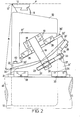
- Fig. 3 presents the foil control means of Fig. 1, viewed in the machine direction.
- Figs 4A and 4B illustrate the functioning of the control means of the invention in various positions, Fig. 4A depicting the means in an operating position in which the foil is lowered, and Fig. 4B shows the foil in its top position, with the foil angle adjusted to be maximum.
- In Figs 1 and 3 is shown a foil means that has been disposed within the loop of the forming wire F of a paper machine, for instance a standard planar (Fourdrinier) wire. The foil means consists of a box-
type frame beam 10 transversal to the wire's direction of travel and on the top surface of which has been affixed arail 11, on which theceramic foil strip 12, continuous or assembled of pieces or equivalent, is mounted in a manner known in itself in the art. The front edge of thefoil strip 12 is denoted with the reference numeral 12'. As shown in Figs 1 and 3, theframe beam 10 carries on both endsvertical mounting flanges 13 and ahorizontal flange 14 connecting these. In thehorizontal flange 14, two elongated holes have been provided, the threadedpins 16 passing therethrough, and thenuts 15, being used to fix theframe beam 10 at both ends, over the position control means of the invention, to be contiguous with theframe components 41 of the paper machine. - The control means of the invention have been disposed at both ends of the
frame beam 10, and these control means on the operator's side and on the drive side of the paper machine are mirror images of each other. These both sets of control means are operated simultaneously towards adjustment of the height position (H) and/or the clearance angle (angle a) of the foil strip 12 (Figs 4A and 4B) in a way which will become apparent later on. - The control means of Figs 1 and 3 comprises the
upper slide member 17, theintermediate slide member 22 and alower slide member 31. To the frame of theupper slide member 17 have been affixed thehorizontal flanges 14 of theframe beam 10 of the dewatering element, by the threadedpins 16 andnuts 15 already mentioned. The threadedpins 16 enter the elongated, wide holes in theflange 14 so that the position of theframe beam 10 with reference to theupper slide 17 can be adjusted to be appropriate. - As taught by the invention, the
upper slide member 17 and theintermediate slide member 22 both have a cylinder shell-shapedsliding surface 20, constituted on the side of theupper slide 17 e.g. byslide blocks 21 of bronze and on the side of theintermediate slide 22, of a stainless sliding surface for instance, Similarly, the sliding parts abutting on each other of the intermediate andlower slides intermediate slide 22 e.g. a slide block of bronze and on the side of the lower slide, a stainless steel face. - The central axis of the radius of curvature R of the
sliding surface 20 coincides with the tip 12' of the foil strip. Thanks to the curvature of the slidingsurface 20 is achieved, as taught by the invention, that when theupper slide 17 is adjusted with reference to theintermediate slide 22 along thesliding surface 20, the position in height of the tip 12' of thefoil strip 12 will not change while the adjustment of clearance angle ( ) is being made. - The
intermediate slide 22 may move linearly along the inclined slidingsurface 30 with reference to thelower slide 31. Thelower slide 31, again, is affixed byfixing blocks 33 andscrews 34 to the so-calledregister rail 41, which is affixed to the wire beam of the paper machine. By moving theintermediate slide 22 on the inclined slidingsurface 30, the height position of thefoil strip 20 can be so adjusted that the clearance angle of the foil (angle a) with reference to the plane of the wire F does not change. - In the favourable embodiment of the invention illustrated by the figures, the
upper slide 17 as well as thelower slide 22 have been arranged to be displaceable by means of one and thesame control screw 23. Saidcontrol screw 23 connects over thebearing component 27 with thelower slide 31. The control screw has a threadedpart 32. On said threadedpart 32 is carried anut block 26, affixed to theflange 18. Theflange 18 has by its top end been affixed withscrews 19 to theupper slide 17. Theflange 18 is not integral with theintermediate slide 22. - In the following is described, with reference to Figs 4A and 4B, the mode of operation and the construction of the control means of the invention in such parts as have not yet been described. Referring now to Fig. 4B, the adjustment of the clearance angle a of the
foil strip 12 shall first be described. For its adjustment, thescrews foil strip 12 to subtend the desired clearance angle a, while its tip edge 12' remains where it is positioned. The magnitude of the angle a can be read on thescale 36 affixed to theintermediate slide 22, under thepointer 35 attached to the upper slide. In the case of foil strips, the range of adjustment of the angle a is for instance 0 to 3°. On completed adjustment of the angle a, thescrews surface 20 constitutes a comparatively large and stable supporting face between the upper andintermediate slides - During adjustment of the height of the
foil 12, as shown in Fig. 4A, the fixing screws 39 and 40 are fastened. In connection with height adjustment, thescrews 28 are first slackened, whereby the interlocking of theintermediate slide 22 andlower slide 31 is released. Next, by simultaneously turning the control screws 23 on the operator's side as well as the drive side, theupper slide 17 andintermediate slide 22, which are rigidly locked together, can be moved as one piece along the inclinedplanar sliding surface 30. The angle of inclination of this sliding surface has been denoted with S in Fig. 4A. The magnitude of the angle β is preferably about 15°. Thus, by moving theslide 22 and theslide 17 thereto fixed along the slidingsurface 30 the distance L, the height position of the foil strip can be made to change in the vertical plane, or in the plane at right angles against the fabric F, by the distance H = L sin β. This causes the position of thefoil strip 12 to change also in the plane of the wire F through the distance M = L . cos β. But this displacement parallel to the plane of the wire F has no detrimental effects in practice, because the distance in the horizontal plane and in the machine direction between two foils following after each other substantially exceeds the distance M. Upon completed adjustment of height H, thescrews 28 are tightened, and the foil position control has now been accomplished. - It is possible with the aid of the sliding
surfaces foil strip 30 in such manner that the foil angle a = 0 and the upper side of thefoil strip 12 is in the plane of the wire F. After this base adjustment, the scales indicating a and H and/or the respective pointers are fixed so as to to give a zero reading. - The structural design here presented is particularly well-suited for use as control means for old foil beams, owing to the mode of attachment of the upper slide and the foil end. If the control means is provided on a new foil, the design can be made in a simpler and less expensive way, for instance by making the upper slide integral with the foil beam. It is to advantage in such case to exchange the locations of the sliding
surfaces - The second embodiment example of the invention, schematically presented in Fig. 2, is similar to that of Fig. 1 in its main features, except that the sliding
surfaces member 12 is adjusted, is located between the upper slide 17' and the intermediate slide 22'. The curved sliding surface 20', serving the adjustment of the angular position a of themember 12, again, is found between the intermediate slide 22' and the lower slide 31'. In other respects the design and operation are like those described in connection with Figs 1 and 3. - In accordance with the present invention has been obtained a structurally simple and sturdy foil strip position control wherein the adjustment of the clearance angle a and of the height H do not affect each other. It is moreover possible, in an advantageous embodiment of the invention, to carry out both adjustments with the same control screws or other equivalent control means.
- Such embodiments are naturally within the scope of the invention in which the clearance angle a and the height H are adjusted by different control screws or equivalent. Also many other variations within the scope of the invention are possible.
- In the following are stated the claims, various details of the invention being allowed to vary and to deviate from the foregoing within the scope of the inventive idea thereby defined.
Claims (8)
in that the control means comprises on both ends of the frame of the stationary member (12) acting on the web a slide member structure comprising:-
in that two of said slide members (17,22,31) present, acting against each other, sliding surfaces (20) shaped to represent part of a cylinder surface and their centre-of-curvature axis coinciding with the straight line defined by the tip edge (12') of said stationary member (12) or being immediately adjacent thereto;
that two of said slide members (17,22,31) present sliding surfaces (30) which are straight in their direction of motion; and
that the means furthermore comprises control means (18,19,23,26,27, 32), with the aid of which by displacing on one hand one of the two slide members and the intermediate slide member (22) with reference to each other along the curved sliding surface (20) the angular position (a) of the member is controlled and on the other hand by displacing the intermediate slide member (22) and the second slide member with reference to each other along the straight sliding surface (30) rectilinearly the distance (H) of the member from the web is controlled independent of the control of angular position.
Applications Claiming Priority (2)
| Application Number | Priority Date | Filing Date | Title |
|---|---|---|---|
| FI813764A FI62873C (en) | 1981-11-25 | 1981-11-25 | ANORDINATION OF PAPER MACHINERY FOR THE PURPOSE OF A PAPER MACHINE |
| FI813764 | 1981-11-25 |
Publications (3)
| Publication Number | Publication Date |
|---|---|
| EP0080447A2 true EP0080447A2 (en) | 1983-06-01 |
| EP0080447A3 EP0080447A3 (en) | 1985-11-21 |
| EP0080447B1 EP0080447B1 (en) | 1988-08-03 |
Family
ID=8514896
Family Applications (1)
| Application Number | Title | Priority Date | Filing Date |
|---|---|---|---|
| EP82850230A Expired EP0080447B1 (en) | 1981-11-25 | 1982-11-15 | Means for controlling the position and location of a stationary member acting on the paper web in a paper machine |
Country Status (5)
| Country | Link |
|---|---|
| US (1) | US4416731A (en) |
| EP (1) | EP0080447B1 (en) |
| CA (1) | CA1184798A (en) |
| DE (1) | DE3278857D1 (en) |
| FI (1) | FI62873C (en) |
Cited By (1)
| Publication number | Priority date | Publication date | Assignee | Title |
|---|---|---|---|---|
| US4865692A (en) * | 1986-08-20 | 1989-09-12 | J. M. Voith Gmbh | Stationary support member for web producing machine |
Families Citing this family (9)
| Publication number | Priority date | Publication date | Assignee | Title |
|---|---|---|---|---|
| US4718983A (en) * | 1986-07-09 | 1988-01-12 | Papyrus Inc. | Forming board structure having an adjustable leading forming board strip |
| US4684441A (en) * | 1986-07-09 | 1987-08-04 | Papyrus Inc. | Method for operably adjusting a leading, forming board strip |
| US5169500A (en) * | 1991-10-15 | 1992-12-08 | Wilbanks International | Adjustable angle foil for paper making machine with rigid foil body and cam actuation means |
| US5421961A (en) * | 1994-09-26 | 1995-06-06 | Miller; Joseph | Forming board position control system |
| US6274002B1 (en) | 1998-06-23 | 2001-08-14 | Wilbanks International, Inc. | Papermaking machine with variable dewatering elements including variable pulse turbulation blades adjusted by computer control system in response to sensors of paper sheet characteristics |
| US6372093B1 (en) | 2001-04-26 | 2002-04-16 | Wilbanks International, Inc. | Adjustable foil apparatus for papermaking machine |
| US9045859B2 (en) | 2013-02-04 | 2015-06-02 | Ibs Of America | Adjustment mechanism |
| US8974639B2 (en) * | 2013-02-04 | 2015-03-10 | Ibs Of America | Angle and height control mechanisms in fourdrinier forming processes and machines |
| US11105043B2 (en) | 2018-05-30 | 2021-08-31 | Ibs Of America | Deckle board system with a slotless deckle seal strip |
Citations (3)
| Publication number | Priority date | Publication date | Assignee | Title |
|---|---|---|---|---|
| US3535201A (en) * | 1967-10-02 | 1970-10-20 | Allis Chalmers Mfg Co | Angularly adjustable support mechanism for fourdrinier drainage foil |
| US3576715A (en) * | 1967-10-02 | 1971-04-27 | Allis Chalmers Mfg Co | Quick lowering mechanism for fourdrinier drainage foil |
| US3819475A (en) * | 1972-07-19 | 1974-06-25 | Int Paper Co | Rotatable papermaking machine support structure therefor |
Family Cites Families (2)
| Publication number | Priority date | Publication date | Assignee | Title |
|---|---|---|---|---|
| GB1024935A (en) * | 1963-09-06 | 1966-04-06 | Ralph Chalinor Heys | Improvements in or relating to paper-making machines |
| GB1028349A (en) * | 1963-09-14 | 1966-05-04 | Millspaugh Ltd | Improvements in or relating to the de-watering of the forming wires of paper making machines |
-
1981
- 1981-11-25 FI FI813764A patent/FI62873C/en not_active IP Right Cessation
-
1982
- 1982-05-10 US US06/376,537 patent/US4416731A/en not_active Expired - Fee Related
- 1982-11-15 DE DE8282850230T patent/DE3278857D1/en not_active Expired
- 1982-11-15 EP EP82850230A patent/EP0080447B1/en not_active Expired
- 1982-11-24 CA CA000416222A patent/CA1184798A/en not_active Expired
Patent Citations (3)
| Publication number | Priority date | Publication date | Assignee | Title |
|---|---|---|---|---|
| US3535201A (en) * | 1967-10-02 | 1970-10-20 | Allis Chalmers Mfg Co | Angularly adjustable support mechanism for fourdrinier drainage foil |
| US3576715A (en) * | 1967-10-02 | 1971-04-27 | Allis Chalmers Mfg Co | Quick lowering mechanism for fourdrinier drainage foil |
| US3819475A (en) * | 1972-07-19 | 1974-06-25 | Int Paper Co | Rotatable papermaking machine support structure therefor |
Cited By (1)
| Publication number | Priority date | Publication date | Assignee | Title |
|---|---|---|---|---|
| US4865692A (en) * | 1986-08-20 | 1989-09-12 | J. M. Voith Gmbh | Stationary support member for web producing machine |
Also Published As
| Publication number | Publication date |
|---|---|
| EP0080447B1 (en) | 1988-08-03 |
| CA1184798A (en) | 1985-04-02 |
| US4416731A (en) | 1983-11-22 |
| DE3278857D1 (en) | 1988-09-08 |
| FI62873C (en) | 1983-03-10 |
| EP0080447A3 (en) | 1985-11-21 |
| FI62873B (en) | 1982-11-30 |
Similar Documents
| Publication | Publication Date | Title |
|---|---|---|
| EP0080447B1 (en) | Means for controlling the position and location of a stationary member acting on the paper web in a paper machine | |
| US4220113A (en) | Device for applying a coating to a material web | |
| EP0456276B1 (en) | Coordinate measuring apparatus | |
| US4113223A (en) | Cross-movable carriage | |
| US3639993A (en) | Improvements relating to machines and apparatus having a support for guiding a movable member | |
| JP3363183B2 (en) | Dewatering foil device for paper machine | |
| US6161298A (en) | Coordinate measuring apparatus having a bridge configuration | |
| US4865692A (en) | Stationary support member for web producing machine | |
| FI63341B (en) | OVER ANCHOR ORDER ATT AVSTRYKA OEVERFLOEDIG STRYKMASSA FRAON EN LOEPANDE BANA | |
| ATE97735T1 (en) | MEASURING DEVICE FOR MEASURING THE DIAMETERS OF ROLLS ON ROLL GRINDING MACHINES. | |
| FI71788C (en) | Device for coating paper web. | |
| JP2930714B2 (en) | Metal sheet bending equipment | |
| US5226577A (en) | Web guide for elongated flexible web | |
| CA1306125C (en) | Apparatus for the axial adjustment of the roll of rolling mills used to produce profile steel | |
| US4477006A (en) | Offset pivot guiding assembly | |
| CA2075090A1 (en) | Doctoring apparatus with flexible blade mounting | |
| US5129992A (en) | Stationary support device for drainage wire | |
| GB1488200A (en) | Device comprising an elogate strip and means for supporting the strip and adjusting its position | |
| US5587051A (en) | Simplified laser apparatus and method for measuring stock thickness on papermaking machines | |
| GB2281749A (en) | Apparatus for needling a nonwoven web | |
| US4614038A (en) | Head for measuring diameters of cylindrical parts | |
| US6408930B1 (en) | Adjustable plate mold | |
| US3738910A (en) | Nozzle adjusting arrangement for a papermaking machine headbox | |
| US3944465A (en) | Headbox assembly for a papermaking machine | |
| US4966653A (en) | Apparatus for controlling a moving band |
Legal Events
| Date | Code | Title | Description |
|---|---|---|---|
| PUAI | Public reference made under article 153(3) epc to a published international application that has entered the european phase |
Free format text: ORIGINAL CODE: 0009012 |
|
| AK | Designated contracting states |
Designated state(s): DE GB IT SE |
|
| PUAL | Search report despatched |
Free format text: ORIGINAL CODE: 0009013 |
|
| AK | Designated contracting states |
Designated state(s): DE GB IT SE |
|
| 17P | Request for examination filed |
Effective date: 19860215 |
|
| 17Q | First examination report despatched |
Effective date: 19870427 |
|
| ITF | It: translation for a ep patent filed |
Owner name: DR. ING. A. RACHELI & C. |
|
| GRAA | (expected) grant |
Free format text: ORIGINAL CODE: 0009210 |
|
| AK | Designated contracting states |
Kind code of ref document: B1 Designated state(s): DE GB IT SE |
|
| REF | Corresponds to: |
Ref document number: 3278857 Country of ref document: DE Date of ref document: 19880908 |
|
| PLBE | No opposition filed within time limit |
Free format text: ORIGINAL CODE: 0009261 |
|
| STAA | Information on the status of an ep patent application or granted ep patent |
Free format text: STATUS: NO OPPOSITION FILED WITHIN TIME LIMIT |
|
| 26N | No opposition filed | ||
| PGFP | Annual fee paid to national office [announced via postgrant information from national office to epo] |
Ref country code: GB Payment date: 19901001 Year of fee payment: 9 |
|
| PGFP | Annual fee paid to national office [announced via postgrant information from national office to epo] |
Ref country code: DE Payment date: 19901113 Year of fee payment: 9 |
|
| PGFP | Annual fee paid to national office [announced via postgrant information from national office to epo] |
Ref country code: SE Payment date: 19901119 Year of fee payment: 9 |
|
| ITTA | It: last paid annual fee | ||
| PG25 | Lapsed in a contracting state [announced via postgrant information from national office to epo] |
Ref country code: GB Effective date: 19911115 |
|
| PG25 | Lapsed in a contracting state [announced via postgrant information from national office to epo] |
Ref country code: SE Effective date: 19911116 |
|
| GBPC | Gb: european patent ceased through non-payment of renewal fee | ||
| PG25 | Lapsed in a contracting state [announced via postgrant information from national office to epo] |
Ref country code: DE Effective date: 19920801 |
|
| EUG | Se: european patent has lapsed |
Ref document number: 82850230.2 Effective date: 19920604 |