EP0080090A1 - Installation for heat transport - Google Patents
Installation for heat transport Download PDFInfo
- Publication number
- EP0080090A1 EP0080090A1 EP82110183A EP82110183A EP0080090A1 EP 0080090 A1 EP0080090 A1 EP 0080090A1 EP 82110183 A EP82110183 A EP 82110183A EP 82110183 A EP82110183 A EP 82110183A EP 0080090 A1 EP0080090 A1 EP 0080090A1
- Authority
- EP
- European Patent Office
- Prior art keywords
- heat exchanger
- heat
- exhaust gas
- air
- transfer device
- Prior art date
- Legal status (The legal status is an assumption and is not a legal conclusion. Google has not performed a legal analysis and makes no representation as to the accuracy of the status listed.)
- Ceased
Links
Images


Classifications
-
- F—MECHANICAL ENGINEERING; LIGHTING; HEATING; WEAPONS; BLASTING
- F28—HEAT EXCHANGE IN GENERAL
- F28D—HEAT-EXCHANGE APPARATUS, NOT PROVIDED FOR IN ANOTHER SUBCLASS, IN WHICH THE HEAT-EXCHANGE MEDIA DO NOT COME INTO DIRECT CONTACT
- F28D15/00—Heat-exchange apparatus with the intermediate heat-transfer medium in closed tubes passing into or through the conduit walls ; Heat-exchange apparatus employing intermediate heat-transfer medium or bodies
-
- F—MECHANICAL ENGINEERING; LIGHTING; HEATING; WEAPONS; BLASTING
- F24—HEATING; RANGES; VENTILATING
- F24D—DOMESTIC- OR SPACE-HEATING SYSTEMS, e.g. CENTRAL HEATING SYSTEMS; DOMESTIC HOT-WATER SUPPLY SYSTEMS; ELEMENTS OR COMPONENTS THEREFOR
- F24D11/00—Central heating systems using heat accumulated in storage masses
- F24D11/006—Central heating systems using heat accumulated in storage masses air heating system
- F24D11/009—Central heating systems using heat accumulated in storage masses air heating system with recuperation of waste heat
Definitions
- the present invention relates to a heat transfer device according to the preamble of the main claim.
- the heat flows occurring within a building preferably a single-family house, for example the exhaust air from the kitchen or the bathroom and the exhaust gases of a fuel-heated heat source in an exhaust gas / exhaust air line, are to be combined and lead to a heat exchanger together, the Fresh air is supplied in counterflow from the atmosphere, which is supplied to individual rooms in the building after heating in the heat exchanger.
- the known solution consists of a large number of components and accordingly requires a high level of installation effort. Furthermore, it is not guaranteed that the exhaust air heat source and the fuel-heated heat source are uniformly available as energy sources for supplying the supply air heat exchanger at foreseeable times.
- the use of the exhaust gas in direct heat exchange with the supply air in the event of leaks in the area of the exhaust gas / supply air heat exchanger entails dangers for people living in the house, since the risk cannot be excluded that toxic components of the exhaust gas (carbon monoxide) are mixed into the supply air .
- the object of the present invention is to enable the waste heat flows occurring in a building to be used safely in order to heat the fresh air or circulating air to be supplied to the rooms in the building.
- Figure nine shows the possibility of inserting a memory
- Transmission device is schematically shown with 1, a room of a residential or industrial building, in which at least one fuel-heated heat source 2, be it a boiler, circulating water heater, continuous water heater, heating oven or the like, is installed. Furthermore, the room itself, if it is provided with a ventilation device 3, represents an exhaust air heat source. Ventilation openings are provided on the room 1, preferably on the ceiling, with which exhaust air can be guided to a collection point 5 via an air duct 4.
- the fuel-heated heat source 2 usually has an exhaust pipe 6, which is also led to the collection point 5. It does not matter whether the fuel-heated heat source 2 is fed by gas, oil or solid fuels.
- the collecting point 5 can either be supplied with exhaust air from several rooms 1, there is also the possibility of bringing together two exhaust pipes at the collecting point 5 from a plurality of heat sources. There is also the further possibility of bringing together several exhaust air ducts as well as exhaust pipes in the area of the collection point.
- a common waste heat line 7 goes from the collection point 5 to an exhaust gas / exhaust air heat exchanger 8, from which it is led into the atmosphere via a chimney 9.
- the waste heat exchanger 8 is connected via lines 10 and 11 to a supply air or circulating air heat exchanger 12, the lines 10 and 11 forming elements of an intermediate medium circuit which contains, for example, water or glycol and in which the intermediate medium may be with the aid of a pump (not shown) or a fan is moved.
- a circulating air line 13, into which a blower 14 is switched on, is connected to the circulating air heat exchanger.
- the circulation line 13 leads in the direction of flow first via the circulating air heat exchanger 12 and then via a heating line 14 into a room 15 to be heated, which room can be a room different from room 1, but can also be the same room.
- the function of the heat transfer device described according to FIG 15 belong, or the control devices of the heating and ventilation system.
- the waste heat from both is collected and transferred to the waste heat exchanger 8 via the waste heat line 7.
- the intermediate circuit of the intermediate medium is heated, which emits its heat to the fresh / circulating air heat exchanger 12.
- the fresh air / circulating air heat exchanger preheats the circulating air to be given into space 15.
- the circulating air heat exchanger can be equipped with a constant outlet temperature control or be provided with heat pipes.
- the exhaust pipe of the individual fuel-heated heat source 2 or the combined exhaust pipes of several fuel-heated heat sources are combined on a separate exhaust gas heat exchanger 20.
- the exhaust gas heat exchanger acts as an exhaust air heat exchanger during downtimes.
- the exhaust air and exhaust gas heat exchanger can form a structural unit.
- the combined vents 3 of all rooms 1 to be vented are combined in a common exhaust air line 4 and placed on a separate exhaust air heat exchanger 21.
- the intermediate medium line 10 has a branch from which a line 24 branches off, likewise there is a branch in the line 11 in which a line 25 opens into the line 11. While the line 10, the intermediate medium in the cooled to was conveyed from the supply air heat exchanger 12 into the exhaust air heat exchanger 21, the exhaust gas heat exchanger 20 is hydraulically connected in parallel to the exhaust air heat exchanger 21 through the lines 24 and 25.
- the fuel-heated heat source 2 is located in the room 30 and is connected via the exhaust pipe 6 to the exhaust gas heat exchanger 20, which is connected directly to the chimney 9.
- a vent 3 is provided, which is connected via a guide 4 to the exhaust air heat exchanger 21, which conveys the exhaust air into the atmosphere via a special pipe 31.
- the supply air duct 22 is also provided, which runs through the supply air heat exchanger 12 and heats a space 32 via a heating line 23, which is connected via a line 33 to the atmosphere as a vent.
- the routing of the intermediate medium differs from the previous examples according to FIGS.
- FIG. Four shows that a heat pipe 37, one end 38 of which can be used as the heat exchange element for the heat transfer device is acted upon by the combined exhaust gas / exhaust air heat exchanger 8, while the other end 39 is assigned to the supply air heat exchanger 12.
- the heat pipe has a liquid which is evaporated in the end 38 under the action of heat supplied.
- the steam reaches the end 39 and condenses on account of the heat given off to the supply air brought in in the duct 22.
- the condensed heat transfer medium flows back to the end 38 at the bottom of the heat pipe due to a slope or pumping action, and the cycle begins again.
- the supply air heat exchanger 12 is divided into several sections that have no connection with one another.
- the supply air duct 22 is led to a separation point 40, from which individual supply air lines 41, 42 and 43 depart, which are supplied via separate heating lines 44 45 and 46 to different rooms 47, 48 and 49 to be heated with hot air.
- the rooms 47 to 49 can be those in which fuel-heated heat sources are installed or which in turn are to be vented by a venting device 3.
- the figure six teaches that instead of a single intermediate circuit, two intermediate circuits 50 and 51 can be provided, each having lines 10 and 11. It is advantageous here to assign one intermediate medium circuit to the exhaust air heat exchanger 21 and the other to the exhaust gas heat exchanger 20.
- the common supply air line 22 is again led to the separation point 40, from which channels 41 and 42 branch, which lead to a supply air heat exchanger split into two elements 52 and 53. It is provided that the supply air heat exchanger element 52 is connected to a room 49 via a heating line 44, while the supply air heat exchanger element 53 is connected to the other room 48 via a heating line 45. Both rooms 48 and 49 can be vented via separate vent lines 33. It is also possible to vent these rooms via the ventilation device 3.
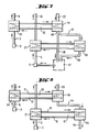
- FIG. Seven a construction of the circuit according to FIG. 6 is possible to lead the supply air in parallel instead of from the separation point 40 in such a way that basic heating of the supply air takes place in a basic heating heat exchanger element 54 and that the separation point 40 lies at the outlet of this basic heating element.
- a heating duct 46 is then led to the basic heating element directly to a room 47, another heating duct is guided via the post-heating element 55, the output line 56 of which is supplied either in the same room 47 or another room to be heated with hot air.
- the exhaust air from the room 47 is discharged via the ventilation device 3.
- the heated fresh air is only partially reheated in the exemplary embodiment according to FIG. Seven, a complete two-stage heating of the fresh air is provided in the exemplary embodiment according to FIG. So the Zu opens Air duct first in the basic heating element 54, but the heating line 44 is looped through the post-heating element 55, so that a two-stage heating of the fresh air or the circulating air is possible.
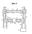
- a memory 60 is provided as an essential element, which is connected via lines 11 and 10 to the exhaust gas heat exchanger 20, which is fed by the fuel-heated heat source 2 via the exhaust pipe 6.
- the exhaust pipe 6 located downstream of the exhaust gas heat exchanger 20 is still looped through the exhaust air heat exchanger 21, which is otherwise fed by the vent 3 through the guide 4. Exhaust gas and exhaust air leave the exhaust air heat exchanger 21 via the chimney 9.
- An intermediate circuit 50 with lines 10 and 11 feeds the supply air heat exchanger 12, to which supply air is supplied via the duct 22.
- Two heating lines 44 and 45 leave the supply air heat exchanger 12, one of which is fed directly to a space 47 to be heated, while the other is guided via a storage heat exchanger 61.
- An output line 62 of the storage heat exchanger likewise leads to room 47 or to another or more rooms.
- the storage heat exchanger is connected via lines 63 and 64 to the storage 60, which may be designed as a domestic water storage. There is thus the possibility of charging the accumulator 60 from the exhaust gas heat exchanger 20 via the intermediate circuit 51 if, for example, a heat source has to be in operation. but no warm air heating in room 47 is desired.
- the storage heat exchanger 61 it is possible to apply the charged content of the storage 60 to the storage heat exchanger 61 via the lines 63 and 64 if air heating in the room 47 is desired, but at this time there is no waste heat from the ventilation 3 or from fuel-heated heat sources or that the waste heat supply is not sufficient.
- the intermediate medium circuit 50 it is possible via the intermediate medium circuit 50 to act on the supply air heat exchanger 12 via the heat exchanger 21, so that the storage heat exchanger 61 in one case represents after-heating as a second stage for the fresh air supplied via the lines 44 and 62, or that at Failure of an exhaust air preheating of the fresh air of the storage heat exchanger 61 takes over the heating of the supplied fresh or possibly recirculated air alone and in one step.
- the exhaust air heat exchanger 21 Since it is not readily apparent to the system designer how high the temperature level of the exhaust gas in line 65, which has already cooled down in the first stage, it is expedient to provide the exhaust air heat exchanger 21 with a plurality of taps. It is now possible to connect the line 65 to one of the taps 66 to 68 after the system has been created and adjusted. The tap for the connection is then selected, in which the temperature level of the exhaust gas corresponds approximately to the temperature level of the exhaust air temperature level, which has already cooled down in the heat exchanger 21. This case is therefore chosen when the temperature level in the exhaust pipe 65 is lower than the temperature level of the exhaust air in the guide 4 on the inlet side of the exhaust air heat exchanger. If, however, the temperature level of the exhaust gas in line 65 is higher than the temperature level of guide 4, line 65 is connected directly to line 4 or to the inlet point. on the heat exchanger 21.
Abstract
Description
Die vorliegende Erfindung bezieht sich auf eine Wärmeübertragungseinrichtung gemäß dem Oberbegriff des Hauptanspruchs.The present invention relates to a heat transfer device according to the preamble of the main claim.
Es ist bekannt, daß die innerhalb eines Gebäudes, vorzugsweise eines Einfamilienhauses, anfallenden Wärmeströme, beispielsweise die Abluft aus der Küche beziehungsweise dem Badezimmer und die Abgase einer brennstoffbeheizten Wärmequelle in einer Abgas-/Abluftleitung, zusammenzufassen und zu einem Wärmetauscher gemeinsam zu führen sind, dem im Gegenstrom Frischluft aus der Atmosphäre zugeführt wird, die nach Aufheizung im Wärmetauscher einzelnen Räumen des Gebäudes zugeführt wird. Die bekannte Lösung besteht aus einer Vielzahl von Komponenten und erfordert demgemäß einen hohen installationstechnischen Aufwand. Weiterhin ist nicht gewährleistet, daß gleichförmig zu voraussehbaren Zeiten die Abluftwärmequelle und die brennstoffbeheizte Wärmequelle als Energiequellen zur Speisung des Zuluftwärmetauschers zur Verfügung stehen. Zudem bringt die Verwendung des Abgases im unmittelbaren Wärmetausch mit der Zuluft bei Undichtigkeiten im Bereich des Abgas-/Zuluftwärmetauschers Gefahren für die das Haus bewohnenden Menschen mit sich, da die Gefahr nicht auszuschließen ist, daß giftige Bestandteile des Abgases (Kohlenmonoxyd) der Zuluft beigemischt werden.It is known that the heat flows occurring within a building, preferably a single-family house, for example the exhaust air from the kitchen or the bathroom and the exhaust gases of a fuel-heated heat source in an exhaust gas / exhaust air line, are to be combined and lead to a heat exchanger together, the Fresh air is supplied in counterflow from the atmosphere, which is supplied to individual rooms in the building after heating in the heat exchanger. The known solution consists of a large number of components and accordingly requires a high level of installation effort. Furthermore, it is not guaranteed that the exhaust air heat source and the fuel-heated heat source are uniformly available as energy sources for supplying the supply air heat exchanger at foreseeable times. In addition, the use of the exhaust gas in direct heat exchange with the supply air in the event of leaks in the area of the exhaust gas / supply air heat exchanger entails dangers for people living in the house, since the risk cannot be excluded that toxic components of the exhaust gas (carbon monoxide) are mixed into the supply air .
Der vorliegenden Erfindung liegt die Aufgabe zugrunde, eine gefahrlose Nutzung der in einem Gebäude anfallenden Abwärmeströme zu ermöglichen, um die den Räumen des Gebäudes zuzuführende Frischluft oder Umluft aufzuheizen.The object of the present invention is to enable the waste heat flows occurring in a building to be used safely in order to heat the fresh air or circulating air to be supplied to the rooms in the building.
Die Lösung dieser Aufgabe gelingt mit denen im kennzeichnenden Teil des Hauptanspruchs angegebenen Merkmalen.This object is achieved with the features specified in the characterizing part of the main claim.
Weitere Ausgestaltungen und besonders vorteilhafte Weiterbildungen der Erfindung gehen aus den Unteransprüchen sowie der nachfolgenden Beschreibung hervor, die eine Vielzahl von Ausführungsbeispielen im einzelnen näher beschreibt.Further refinements and particularly advantageous developments of the invention emerge from the subclaims and the following description, which describes a large number of exemplary embodiments in more detail.
Es zeigen
- Figur eins eine Schaltung der Wärmeübertragungseinrichtung,
- Figur zwei eine Variante zu Figur eins,
- Figur drei eine weitere Variante zur Schaltung nach Figur eins,
- die Figur vier die Verwendung eines Wärmerohres als Wärmetauscher,
- die Figur fünf die Verwendung der Erfindung zur Speisung mehrerer Zuluftströme, mit der Möglichkeit, gleiche oder verschiedene Temperaturniveaus auszunutzen,
- die Figur sechs eine Aufteilung der Zuluftströme,
- die Figur sieben eine Aufteilung der Zuluftströme mit Teilserienschaltung,
- die Figur acht eine besondere Möglichkeit zur intensiven Aufheizung der Zuluft,
- FIG. One shows a circuit of the heat transfer device,
- Figure two shows a variant of figure one,
- FIG. Three shows a further variant of the circuit according to FIG. One,
- FIG. four shows the use of a heat pipe as a heat exchanger,
- FIG. five shows the use of the invention for feeding a plurality of supply air streams, with the possibility of using the same or different temperature levels,
- FIG. 6 shows a division of the supply air flows,
- FIG. seven shows a division of the supply air flows with partial series connection,
- FIG. eight shows a special possibility for intensive heating of the supply air,
Figur neun die Möglichkeit der Einfügung eines Speichers undFigure nine shows the possibility of inserting a memory and
Figur zehn eine Prüfung des Abgases durch eine Serienschaltung des Abgas-/-luftwärmetauschers.Figure ten a test of the exhaust gas by a series connection of the exhaust gas / air heat exchanger.
In allen neun Figuren bedeuten gleiche Bezugszeichen jeweils die gleichen Einzelheiten.In all nine figures, the same reference numerals denote the same details.
Bei der in der Figur eins dargestellten Schaltung der Wärmeübertragungseinrichtung ist mit 1 schematisch ein Raum eines Wohn- oder Industriegebäudes dargestellt, in dem wenigstens eine brennstoffbeheizte Wärmequelle 2, sei es ein Kessel, Umlaufwasserheizer, Durchlauf-Wasserheizer, Heizofen oder dergleichen, aufgestellt ist. Weiterhin stellt der Raum selbst, wenn er mit einer Entlüftungsvorrichtung 3 versehen ist, eine Abluftwärmequelle dar. An dem Raum 1 sind, vorzugsweise an der Decke, Entlüftungsöffnungen vorgesehen, mit denen über eine Luftführung 4 Abluft bis zu einer Sammelstelle 5 geführt werden kann. Die brennstoffbeheizte Wärmequelle 2 weist üblicherweise ein Abgasrohr 6 auf, das gleichermaßen zur Sammelstelle 5 geführt ist. Es ist gleichgültig, ob die brennstoffbeheizte Wärmequelle 2 von Gas, Öl oder festen Brennstoffen gespeist ist. Der Sammelstelle 5 kann entweder aus mehreren Räumen 1 Abluft zugeführt werden, es besteht auch die Möglichkeit, von einer Mehrzahl von Wärmequellen 2 Abgasrohre an der Sammelstelle 5 zusammenzuführen. Es besteht auch die weitere Möglichkeit, im Bereich der Sammelstelle sowohl mehrere Abluftführungen als auch Abgasrohre zusammenzuführen.In the circuit of heat shown in Figure 1 Transmission device is schematically shown with 1, a room of a residential or industrial building, in which at least one fuel-heated
Es besteht weiterhin die Möglichkeit, den Abluft-/Abgaswärmetauscher mit dem Heizgerät baulich zu kombinieren.There is also the option of structurally combining the exhaust air / exhaust gas heat exchanger with the heater.
Von der Sammelstelle 5 geht eine gemeinsame Abwärmeleitung 7 zu einem Abgas-/Abluftwärmetauscher 8, von dem sie über einen Schornstein 9 in die Atmosphäre geführt ist. Im Zuge der Abwärmeleitung 7 oder im Bereich des Schornsteins 9 oder auch im Bereich des Abgas-/Abluftwärmetauschers 8 ist ein nicht weiter dargestelltes Gebläse vorgesehen. Der Abwärmetauscher 8 ist über Leitungen 10 und 11 mit einem Zuluft-oder Umluftwärmetauscher 12 verbunden, wobei die Leitungen 10 und 11 Elemente eines Zwischenmedium-Kreislaufs bilden, der beispielsweise Wasser oder Glykol enthält und bei dem das Zwischenmedium gegebenenfalls mit Hilfe einer nicht weiter dargestellten Pumpe oder eines Gebläses bewegt wird. An den Umluftwärmetauscher ist eine Umluftleitung 13 angeschlossen, in die ein Gebläse 14 eingeschaltet ist. Die Umlaufleitung 13 führt in Strömungsrichtung zunächst über den Umluftwärmetauscher 12 und anschließend über eine Heizleitung 14 in einen zu beheizenden Raum 15, der ein vom Raum 1 abweichender Raum, aber auch derselbe Raum sein kann. Die Funktion der gemäß Figur eins beschriebenen Wärmeübertragungseinrichtung ist folgende: an im Abwärmetauscher nutzbarer Abwärme stehen die Wärmequellen 2 und 3 zur Verfügung, die ständig gleichzeitig Wärme liefern können oder auch intermittierend oder abwechselnd, je nach den jeweiligen Gegebenheiten des Gebäudes, dem die Räume 1 und 15 angehören, beziehungsweise den Regeleinrichtungen der Heiz- und Lüftungsanlage. Die Abwärme beider wird gesammelt und über die Abwärmeleitung 7 auf den Abwärmetauscher 8 gegeben. Im Abwärmetauscher wird der Zwischenkreislauf des Zwischenmediums aufgeheizt, das seine Wärme an den Frisch-/Umluftwärmetauscher 12 abgibt. Mit dem Frisch-/Umluftwärmetauscher wird die in den Raum 15 zu gebende Umlaufluft vorgeheizt. Der Umluftwärmetauscher kann mit einer Konstant-Auslaß-Temperaturregelung oder auch mit Wärmerohren versehen werden.A common
Bei der Ausführung gemäß Figur zwei besteht der wesentliche Unterschied darin, daß das Abgasrohr der einzelnen brennstoffbeheizten Wärmequelle 2 oder die zusammengefaßten Abgasrohre mehrerer brennstoffbeheizter Wärmequellen zusammengefaßt auf einen gesonderten Abgaswärmetauscher 20 gegeben sind. Bei atmosphärischen Brennern wirkt der Abgaswärmetauscher während der Stillstandzeiten als Abluftwärmetauscher. Der Abluft- und Abgaswärmetauscher können eine bauliche Einheit bilden. Auch die zusammengefaßten Entlüftungen 3 sämtlicher zu entlüftender Räume 1 sind in einer gemeinsamen Abluftleitung 4 zusammengefaßt und auf einen gesonderten Abluftwärmetauscher 21 gegeben. Den Abgas- beziehungsweise Abluftwärmetauscher verläßt jeweils eine Leitung 26, die zu der stromabliegenden Sammelstelle 5 geführt ist, von dort gehen beide Mediumströme, nachdem ihnen die nutzbare Wärme in den Wärmetauschern entzogen wurde, in den Schornstein 9. Statt einer Umluftheizung gemäß Figur eins ist bei der Figur zwei eine Frischluftheizung gewählt worden, so wird die Frischluft mittels eines Kanals 22 der Atmosphäre genommen und in dem vom Zwischenmedium gespeisten Zuluftwärmetauscher 12 aufgeheizt und über die Frischluftheizleistung 23 dem oder den zu beheizenden Räumen 1 gegeben. Die Zwischenmediumleitung 10 weist eine Abzweigung auf, von der eine Leitung 24 abgeht, gleichermaßen befindet sich in der Leitung 11 eine Verzweigung, in der eine Leitung 25 in die Leitung 11 einmündet. Während die Leitung 10 das Zwischenmedium im abgekühlten Zustand vom Zuluftwärmetauscher 12 in den Abluftwärmetauscher 21 fördert, ist der Abgaswärmetauscher 20 durch die Leitungen 24 und 25 hydraulisch parallel zum Abluftwärmetauscher 21 geschaltet.In the embodiment according to FIG. Two, the main difference is that the exhaust pipe of the individual fuel-heated
Beim Ausführungsbeispiel gemäß Figur drei steht im Raum 30 die brennstoffbeheizte Wärmequelle 2, die über das Abgasrohr 6 mit dem Abgaswärmetauscher 20 verbunden ist, der direkt an den Schornstein 9 angeschlossen ist. In einem hiervon abhängigen und/oder unabhängigen Raum 1 ist eine Entlüftung 3 vorgesehen, die über eine Führung 4 mit dem Abluftwärmetauscher 21 verbunden ist, der über ein besonderes Rohr 31 die Abluft in die Atmosphäre fördert. Es ist weiterhin der Zuluftkanal 22 vorgesehen, der durch den Zuluftwärmetauscher 12 geführt und über eine Heizleitung 23 einen Raum 32 aufheizt, der über eine Leitung 33 mit der Atmosphäre als Entlüftung verbunden ist. Die Leitungsführung des Zwischenmediums weicht von den bisherigen Beispielen nach Figur eins und zwei dadurch ab, daß eine Leitung 34 das im Zuluftwärmetauscher 12 abgekühlte Medium unmittelbar zum Abluftwärmetauscher 21 führt. Für das Zwischenmedium in Serie schaltet die Leitung 35 den Abgaswärmetauscher 20, von dem eine weitere Leitung 36 für das Zwischenmedium zum Zuluftwärmetauscher 12 führt. Das Zwischenmedium wird somit im Abluftwärmetauscher 21 in einer ersten Stufe, im Abgaswärmetauscher 20 in einer zweiten Nachheizstufe aufgeheizt. Figur vier zeigt, daß als Wärmetauschelement für die Wärmeübertragungseinrichtung ein Wärmerohr 37 Verwendung finden kann, dessen eines Ende 38 von dem hier kombinierten Abgas-/ Abluftwärmetauscher 8 beaufschlagt wird, während das andere Ende 39 dem Zuluftwärmetauscher 12 zugeordnet ist. Das Wärmerohr besitzt eine Flüssigkeit, die unter der Einwirkung zugeführter Wärme im Ende 38 verdampft wird. Der Dampf gelangt zum Ende 39 und kondensiert aufgrund der Wärmeabgabe an die im Kanal 22 herangeführte Zuluft. Das kondensierte Wärmeträgermedium fließt am Boden des Wärmerohres aufgrund Gefälles oder Pumpwirkung zum Ende 38 zurück, und der Kreislauf beginnt von neuem.In the exemplary embodiment according to FIG. Three, the fuel-heated
Gemäß Figur fünf ist es möglich, im Bereich der Zuluft Aufteilungsmöglichkeiten vorzusehen. So ist der Zuluftwärmetauscher 12 in mehrere Sektionen, die miteinander keinen Zusammenhang haben, unterteilt. Der Zuluftkanal 22 ist bis zu einer Trennstelle 40 geführt, von der einzelne Zuluftleitungen 41, 42 und 43 abgehen, die über getrennte Heizleitungen 44 45 und 46 unterschiedlichen mit Warmluft zu beheizenden Räumen 47, 48 und 49 zugeführt sind. Die Räume 47 bis 49 können solche sein, in denen brennstoffbeheizte Wärmequellen aufgestellt sind oder die wiederum durch eine Entlüftungsvorrichtung 3 zu entlüften sind.According to FIG. Five, it is possible to provide distribution options in the area of the supply air. The supply
Die Figur sechs lehrt, daß man statt eines einzigen Zwischenkreislaufs auch zwei Zwischenkreisläufe 50 und 51 vorsehen kann, die jeweils Leitungen 10 und 11 aufweisen. Hierbei ist es vorteilhaft, jeweils einen Zwischenmedium-Kreislauf dem Abluftwärmetauscher 21 und den anderen dem Abgaswärmetauscher 20 zuzuordnen. Die gemeinsame Zuluftleitung 22 ist wiederum bis zur Trennstelle 40 geführt, von der sich Kanäle 41 und 42 verzweigen, die zu einem in zwei Elemente 52 und 53 aufgespaltenen Zuluftwärmetauscher führen. Hierbei ist vorgesehen, daß das Zuluftwärmetauscher-Element 52 über eine Heizleitung 44 mit einem Raum 49 verbunden ist, während das Zuluftwärmetauscher-Element 53 über eine Heizleitung 45 mit dem anderen Raum 48 verbunden ist. Beide Räume 48 und 49 können über gesonderte Entlüftungsleitungen 33 entlüftet werden. Es besteht auch die Möglichkeit, die Entlüftung dieser Räume über die Entlüftungsvorrichtung 3 vorzunehmen.The figure six teaches that instead of a single intermediate circuit, two
Gemäß Figur sieben ist ein Aufbau der Schaltung nach Figur sechs möglich, die Zuluft statt ab der Trennstelle 40 parallel auch so zu führen, daß eine Grundaufheizung der Zuluft in einem Grundaufheizungs-Wärmetauscherelement 54 stattfindet und daß die Trennstelle 40 am Ausgang dieses Grundaufheiungselementes liegt. Ein Heizkanal 46 ist anschließend an das Grundaufheizungselement direkt zu einem Raum 47 geführt, ein anderer Heizkanal ist über das Nachheizelement 55 geführt, dessen Ausgangsleitung 56 entweder im gleichen Raum 47 oder einem anderen mit Warmluft aufzuheizenden Raum zugeführt ist. Die Abluft aus dem Raum 47 wird über die Entlüftungsvorrichtung 3 abgeführt.According to FIG. Seven, a construction of the circuit according to FIG. 6 is possible to lead the supply air in parallel instead of from the
Während beim Ausführungsbeispiel gemäß Figur sieben die aufgeheizte Frischluft nur teilweise nachgeheizt wird, ist im Ausführungsbeispiel nach Figur acht eine komplette zweistufige Aufheizung der Frischluft vorgesehen. So mündet der Zuluftkanal zunächst im Grundaufheizungselement 54, die Heizleitung 44 ist aber durch das Nachheizelement 55 durchgeschleift, so daß eine zweistufige Aufheizung der Frischluft oder auch der Umluft möglich ist.While the heated fresh air is only partially reheated in the exemplary embodiment according to FIG. Seven, a complete two-stage heating of the fresh air is provided in the exemplary embodiment according to FIG. So the Zu opens Air duct first in the
Bei dem Ausführungsbeispiel nach Figur neun ist als wesentliches Element ein Speicher 60 vorgesehen, der über die Leitungen 11 und 10 mit dem Abgaswärmetauscher 20 verbunden ist, der über das Abgasrohr 6 von der brennstoffbeheizten Wärmequelle 2 gespeist ist. Als Besonderheit ist hier noch vorgesehen, daß sich das stromab des Abgaswärmetauschers 20 befindliche Abgasrohr 6 noch durch den Abluftwärmetauscher 21 geschleift ist, der im übrigen durch die Führung 4 von der Entlüftung 3 gespeist ist. Abgas und Abluft verlassen den Abluftwärmetauscher 21 über den Schornstein 9. Ein Zwischenkreislauf 50 mit Leitungen 10 und 11 speist den Zuluftwärmetauscher 12, dem Zuluft über den Kanal 22 zugeführt ist. Den Zuluftwärmetauscher 12 verlassen zwei Heizleitungen 44 und 45, von denen die eine direkt einem zu beheizenden Raum 47 zugeführt ist, während die andere über einen Speicherwärmetauscher 61 geführt ist. Eine Ausgangsleitung 62 des Speicherwärmetauschers führt gleichermaßen zum Raum 47 oder zu einem anderen oder mehreren Räumen. Der Speicherwärmetauscher ist über Leitungen 63 und 64 an den Speicher 60, der gegebenenfalls als Brauchwasserspeicher ausgebildet ist, angeschlossen. Somit besteht die Möglichkeit, vom Abgaswärmetauscher 20 über den Zwischenkreislauf 51 den Speicher 60 aufzuladen, wenn beispielsweise eine Wärmequelle in Betrieb sein muß, aber keine Warmluftheizung im Raum 47 gewünscht ist. Andererseits ist es möglich, mit dem aufgeladenen Inhalt des Speichers 60 über die Leitungen 63 und 64 den Speicherwärmetauscher 61 zu beaufschlagen, wenn eine Luftheizung im Raum 47 gewünscht ist, aber zu diesem Zeitpunkt keine Abwärme aus der Entlüftung 3 oder aus brennstoffbeheizten Wärmequellen vorhanden ist oder daß die Abwärmelieferung nicht ausreicht. Völlig unabhängig hiervon ist es über den Zwischenmedium-Kreislauf 50 möglich, über den Wärmetauscher 21 den Zuluftwärmetauscher 12 zu beaufschlagen, so daß der Speicherwärmetauscher 61 im einen Fall eine Nachheizung als zweite Stufe für die über die Leitungen 44 und 62 zugeführte Frischluft darstellt oder daß bei Ausfall einer Abluftvorwärmung der Frischluft der Speicherwärmetauscher 61 allein und einstufig die Aufheizung der zugeführten Frisch- oder gegebenenfalls Umluft übernimmt.In the exemplary embodiment according to FIG. 9, a
Aus der Figur 10 ist ersichtlich, daß im Zuge des Abgasweges, also des Abgasrohres 6, der eigentliche Abgaswärmetauscher 20 über eine Leitung 65, die in eine Vielzahl von Verzweigungen 66, 67, 68 ausmündet, mit dem Abluftwärmetauscher 21 verbunden ist, das Abgas verläßt zusammen mit der dem Abluftwärmetauscher 21 zugeführten Luft aus der Führung 4 den Abluftwärmetauscher über den Schornstein 9. Diese Schaltung hat den Vorteil, daß man das Temperaturniveau des Abgases, das nach der Abkühlung im Abgaswärmetauscher 20 immer noch etwa dem Niveau entspricht, das die Luft in der Führung 4 aufweist, im Abluftwärmetauscher 21 noch einmal herunterkühlen kann, um die dort befindliche Wärme ausnutzen zu können. Da für den Anlagenplaner nicht ohne weiteres ersichtlich ist, wie hoch das Temperaturniveau des in der ersten Stufe bereits heruntergeklihlten Abgases in der Leitung 65 ist, ist es zweckmäßig, den Abluftwärmetauscher 21 mit einer Mehrzahl von Anzapfungen zu versehen. Es besteht nun die Möglichkeit, nach der Erstellung und Einjustierung der Anlage die Leitung 65 mit einer der Anzapfungen 66 bis 68 zu verbinden. Es wird dann die Anzapfung zur Verbindung ausgewählt, bei der das Temperaturniveau des Abgases etwa dem Temperaturniveau des teilweise bereits im Wärmetauscher 21 heruntergekühlten Abluft-Temperaturniveaus entspricht. Dieser Fall wird also dann gewählt, wenn das Temperaturniveau in der Abgasleitung 65 tiefer ist als das Temperaturniveau der Abluft in der Führung 4 eingangsseitig des Abluftwärmetauschers. Ist das Temperaturniveau des Abgases in der Leitung 65 hingegen höher als das Temperaturniveau der Führung 4, wird die Leitung 65 direkt mit der Leitung 4 verbunden oder mit der Einlaßstelle . am Wärmetauscher 21.It can be seen from FIG. 10 that in the course of the exhaust gas path, that is to say the
Es besteht auch die Möglichkeit, eine der Anzapfungen 60 bis 68 oder die Anzapfung an der Führung 4 von einem Temperaturfühler anzusteuern, wobei die Leitung 65 jeweils mit der Anzapfung beziehungsweise mit dem Einlaß des Abluftwärmetauschers 21 in Verbindung gebracht wird, die in ihrem Temperaturniveau abluftseitig dem Abgastemperaturniveau entspricht.There is also the possibility of controlling one of the
Claims (13)
Applications Claiming Priority (2)
| Application Number | Priority Date | Filing Date | Title |
|---|---|---|---|
| DE3146577 | 1981-11-20 | ||
| DE3146577 | 1981-11-20 |
Publications (1)
| Publication Number | Publication Date |
|---|---|
| EP0080090A1 true EP0080090A1 (en) | 1983-06-01 |
Family
ID=6147091
Family Applications (1)
| Application Number | Title | Priority Date | Filing Date |
|---|---|---|---|
| EP82110183A Ceased EP0080090A1 (en) | 1981-11-20 | 1982-11-05 | Installation for heat transport |
Country Status (1)
| Country | Link |
|---|---|
| EP (1) | EP0080090A1 (en) |
Cited By (4)
| Publication number | Priority date | Publication date | Assignee | Title |
|---|---|---|---|---|
| EP0148988A2 (en) * | 1984-01-14 | 1985-07-24 | Vereinigte Elektrizitätswerke Westfalen AG | Process and apparatus for heating the air, especially for dwellings |
| GB2198227A (en) * | 1986-10-24 | 1988-06-08 | Anthony Rack | Energy conservation system and method |
| FR2792681A1 (en) * | 1999-04-21 | 2000-10-27 | Anghel Muscocea | Anti-pollution device for vehicles and industrial chimneys, comprises electrical motors which drive turbines to blow gases into coils which cool gases |
| WO2013004277A1 (en) * | 2011-07-01 | 2013-01-10 | Statoil Petroleum As | Subsea heat exchanger and method for temperature control |
Citations (2)
| Publication number | Priority date | Publication date | Assignee | Title |
|---|---|---|---|---|
| NL7602651A (en) * | 1976-03-12 | 1977-09-14 | Amgas Bv | Heat energy recovery equipment - has stale air discharge combined with smoke chimney supplying fresh air heat exchanger |
| FR2451548A1 (en) * | 1979-03-12 | 1980-10-10 | Totalgaz Cie Fse | Warm air heating with heat pump - involves supplementary heating utilising liq. or gaseous fuel during extreme conditions |
-
1982
- 1982-11-05 EP EP82110183A patent/EP0080090A1/en not_active Ceased
Patent Citations (2)
| Publication number | Priority date | Publication date | Assignee | Title |
|---|---|---|---|---|
| NL7602651A (en) * | 1976-03-12 | 1977-09-14 | Amgas Bv | Heat energy recovery equipment - has stale air discharge combined with smoke chimney supplying fresh air heat exchanger |
| FR2451548A1 (en) * | 1979-03-12 | 1980-10-10 | Totalgaz Cie Fse | Warm air heating with heat pump - involves supplementary heating utilising liq. or gaseous fuel during extreme conditions |
Non-Patent Citations (1)
| Title |
|---|
| REVUE PRATIQUE DU FROID ET DU CONDITIONNEMENT D'AIR, Band 30, Nr. 418, 15. März 1977, Seiten 35-40, Paris, FR. * |
Cited By (11)
| Publication number | Priority date | Publication date | Assignee | Title |
|---|---|---|---|---|
| EP0148988A2 (en) * | 1984-01-14 | 1985-07-24 | Vereinigte Elektrizitätswerke Westfalen AG | Process and apparatus for heating the air, especially for dwellings |
| DE3401136A1 (en) * | 1984-01-14 | 1985-07-25 | Vereinigte Elektrizitätswerke Westfalen AG, 4600 Dortmund | METHOD AND DEVICE FOR HEATING THE INDOOR AIR, IN PARTICULAR APARTMENTS |
| EP0148988A3 (en) * | 1984-01-14 | 1986-03-19 | Vereinigte Elektrizitatswerke Westfalen Ag | Process and apparatus for heating the air, especially for dwellings |
| GB2198227A (en) * | 1986-10-24 | 1988-06-08 | Anthony Rack | Energy conservation system and method |
| FR2792681A1 (en) * | 1999-04-21 | 2000-10-27 | Anghel Muscocea | Anti-pollution device for vehicles and industrial chimneys, comprises electrical motors which drive turbines to blow gases into coils which cool gases |
| WO2013004277A1 (en) * | 2011-07-01 | 2013-01-10 | Statoil Petroleum As | Subsea heat exchanger and method for temperature control |
| GB2506798A (en) * | 2011-07-01 | 2014-04-09 | Statoil Petroleum As | Subsea heat exchanger and method for temperature control |
| AU2011372734B2 (en) * | 2011-07-01 | 2017-01-05 | Statoil Petroleum As | Subsea heat exchanger and method for temperature control |
| GB2506798B (en) * | 2011-07-01 | 2018-04-25 | Statoil Petroleum As | Subsea heat exchanger and method for temperature control of the heat exchanger |
| NO342365B1 (en) * | 2011-07-01 | 2018-05-14 | Statoil Petroleum As | Submarine heat exchanger and temperature control method |
| US10317109B2 (en) | 2011-07-01 | 2019-06-11 | Statoil Petroleum As | Subsea heat exchanger and method for temperature control |
Similar Documents
| Publication | Publication Date | Title |
|---|---|---|
| EP0001419B1 (en) | Installation with a heat pump for central heating and for domestic water heating | |
| DE69923100T2 (en) | boiler | |
| DE102006007848B4 (en) | Installation for heating a facility such as a hall at a high temperature level that needs to be dehumidified, in particular a swimming pool hall | |
| DE2950901A1 (en) | CENTRAL HEATING SYSTEM | |
| DE4321878C1 (en) | Method and device for recovering heat from the exhaust gases of combustion plants with a heat exchanger | |
| EP0080090A1 (en) | Installation for heat transport | |
| DE19714760C2 (en) | Exhaust gas converter | |
| EP0098481B1 (en) | Method for generating electric power in a combined power plant with fluidised bed combustion | |
| DE10245571B4 (en) | More ways mixing valve assembly | |
| DE3308700C2 (en) | Equipment for heating and ventilation | |
| EP0148988B1 (en) | Process and apparatus for heating the air, especially for dwellings | |
| DE3244373C2 (en) | Air heating system | |
| EP0050687A1 (en) | Hot-air turbines steam power plant | |
| DE3240833C2 (en) | Heat transfer device | |
| DE2846728A1 (en) | Heating and refrigerating system with gas absorber - utilises heat released on evaporation and refrigerates on condensation | |
| DE202006003153U1 (en) | Heat energy recovery assembly for oil- or gas-fired bread baking oven has ultra thin heat exchanger housing | |
| DE4112522C1 (en) | Appts. for recovering dry and latent heat from oil or gas exhaust - comprising heat exchanger in several stages in flue, with circulation from heating return pipe to first stage, etc. | |
| EP0083726A1 (en) | Installation for air heating | |
| DE8133817U1 (en) | HEAT TRANSFER DEVICE | |
| EP1172874A2 (en) | High temperature fuel cells installation | |
| DE3620495A1 (en) | Air-heating insert for a fireplace or tiled stove | |
| AT204334B (en) | Process for utilizing the waste heat from gas turbine systems consisting of one or more free piston gas generators and one or more downstream gas turbines for the operation of heating systems and system for carrying out the process | |
| DE202017104879U1 (en) | Heating system with jet lines | |
| DE3225387A1 (en) | Heating boiler | |
| DE2758181A1 (en) | Central heating boiler exhaust heat reclamation - uses vessel with gas inlets and outlets, and internal gas deflection plates |
Legal Events
| Date | Code | Title | Description |
|---|---|---|---|
| PUAI | Public reference made under article 153(3) epc to a published international application that has entered the european phase |
Free format text: ORIGINAL CODE: 0009012 |
|
| AK | Designated contracting states |
Designated state(s): AT DE FR NL |
|
| 17P | Request for examination filed |
Effective date: 19830906 |
|
| STAA | Information on the status of an ep patent application or granted ep patent |
Free format text: STATUS: THE APPLICATION HAS BEEN REFUSED |
|
| 18R | Application refused |
Effective date: 19850525 |
|
| RIN1 | Information on inventor provided before grant (corrected) |
Inventor name: LUEBKE, PETER |