EP0080025B1 - Analogue indicating device, particularly a tachometer - Google Patents
Analogue indicating device, particularly a tachometer Download PDFInfo
- Publication number
- EP0080025B1 EP0080025B1 EP82107422A EP82107422A EP0080025B1 EP 0080025 B1 EP0080025 B1 EP 0080025B1 EP 82107422 A EP82107422 A EP 82107422A EP 82107422 A EP82107422 A EP 82107422A EP 0080025 B1 EP0080025 B1 EP 0080025B1
- Authority
- EP
- European Patent Office
- Prior art keywords
- frequency
- pointer
- stop
- pulse
- stepping motor
- Prior art date
- Legal status (The legal status is an assumption and is not a legal conclusion. Google has not performed a legal analysis and makes no representation as to the accuracy of the status listed.)
- Expired
Links
Images
Classifications
-
- G—PHYSICS
- G01—MEASURING; TESTING
- G01D—MEASURING NOT SPECIALLY ADAPTED FOR A SPECIFIC VARIABLE; ARRANGEMENTS FOR MEASURING TWO OR MORE VARIABLES NOT COVERED IN A SINGLE OTHER SUBCLASS; TARIFF METERING APPARATUS; MEASURING OR TESTING NOT OTHERWISE PROVIDED FOR
- G01D11/00—Component parts of measuring arrangements not specially adapted for a specific variable
- G01D11/16—Elements for restraining, or preventing the movement of, parts, e.g. for zeroising
-
- G—PHYSICS
- G01—MEASURING; TESTING
- G01P—MEASURING LINEAR OR ANGULAR SPEED, ACCELERATION, DECELERATION, OR SHOCK; INDICATING PRESENCE, ABSENCE, OR DIRECTION, OF MOVEMENT
- G01P1/00—Details of instruments
- G01P1/04—Special adaptations of driving means
Definitions
- the invention relates to an analog display device, in particular a tachometer according to the preamble of claim 1.
- the tachometer mentioned here is a so-called electronic tachometer, in which a pulse frequency proportional to the speed of the vehicle is evaluated, by means of a stepper motor, a pointer or to adjust a speedometer needle.
- the analog display device of the type mentioned above is not limited to electronic tachometers, but generally relates to a display device for state variables that are to be displayed in analog form.
- a pointer is deflected by a reversible stepper motor via a gear.
- a gear wheel of the transmission on the axis of which the pointer is mounted, has an approximately semicircular cutout into which a stop pin extends. This stop pin limits the pointer deflection in the zero position and in the end deflection position.
- the stepper motor is fed by a pulse organizer with a preparation input via a stepper motor control circuit.
- the pulse generator also feeds an up-down counter, the outputs of which are connected to a comparison circuit.
- the comparison circuit is connected to measured value inputs into which signals corresponding to the measured value are fed in the same digital form as the counter reading of the up-down counter is output.
- Outputs of the comparison circuit are connected on the one hand via an AND gate to an up-down control input of the up-down counter and a forward-backward control of the stepper motor control circuit and on the other hand via a second AND gate to the preparation input of the pulse generator.
- Two further inputs of said first and second AND gates are controlled by the output of a flip-flop which has a reset input for receiving a reset signal. The reset signal forms a reset command for the pulse generator in conjunction with the flip-flop.
- the up-down counter When a reset signal occurs, the up-down counter is reset to zero and the flip-flop is flipped to a position which issues a reset command to the preparation input of the pulse generator.
- the pulse generator then delivers pulses to the stepper motor as well as to the up-down counter via the stepper motor control circuit. This causes the up-down counter to count down and the stepper motor to reset the pointer step by step. This process continues until the counting capacity of the up-down counter is reached, i.e. the same number of pulses is always delivered to the stepper motor for resetting.
- the cutout in the gear wheel connected to the pointer inevitably comes into engagement with the stop pin in the zero position of the pointer, as a result of which the pointer is stopped in the zero position. In this position, the pointer and the up-down counter are synchronized with each other.
- the reset process can take place each time the analog display device is switched on or with the aid of a detector (DE-A-29 46 328).
- a disadvantage of this analog display device is that the stop in the zero position is loaded by the gear unit with a considerable torque of the stepping motor if the pointer is not reset from its full deflection but from a lower value.
- the momentum of the motor with the gearbox which further increases the load on the stop and the gearbox, so that in view of the load caused by the normal driving torque of the motor, the reset must be carried out at a limited speed if the gearbox does not have high strength properties and is constructed with a larger moment of inertia.
- the object of the present invention is therefore to further develop an analog display device of the type mentioned at the beginning with a resetting of the stepping motor with a constant number of pulses such that the load on the mechanical parts of the display device, in particular the stop and the transmission, is relatively low, and that nevertheless, the reset is quick and reliable.
- the stepper motor is initially subjected to a relatively low-frequency pulse sequence at the beginning of the reset phase, the frequency of which is below the start-stop frequency of the stepper motor, the stepper motor starts reliably and synchronously with the pulses. Only then will the pulse rate be increased to values above the start-stop rate. This not only accelerates the resetting, but the drive torque drops as the frequency increases due to the usual characteristics of the stepper motor. This has the desired consequence that the drive torque is relatively low when the stop is reached when the pointer is in the zero position. In this analog display device, the mechanical parts can therefore be designed to be relatively low-mass. Despite the accelerated reset, the synchronization between pointer position and pulse number is maintained, ie the pointer is also reliably reset from the full deflection.
- a particularly inexpensive implementation of the analog display device with the controlled pulse generator is that it is designed as a ramp generator that increases the pulse frequency from below the start-stop frequency to the maximum operating frequency of the stepper motor.
- This ramp generator also ensures a particularly reliable synchronization of the stepper motor movement with the feeding pulses.
- the pulse generator can be controlled by a voltage detector. After the normal battery voltage has been switched off, the analog display device can be supplied via another connection to the battery or by means of an auxiliary battery.
- the analog display device with a gear wheel driving the pointer which is connected to the stepper motor, is designed, for example, in such a way that the gear wheel has a cutout that is proportional to the end stop of the pointer and that forms two end stops in connection with a stationary stop pin .
- the fixed stop pin does not come into direct contact with the pointer during these stops, it is particularly suitable for resetting with a number of pulses which is greater than is necessary until the stop is reached in the zero position.
- the cutout of the gearwheel can better absorb the impulses and forces when the stop pin strikes than the pointer directly.
- a circuit for accelerating and braking a stepper motor is known.
- a function generator feeds a voltage-controlled oscillator with a ramp-like rising or falling voltage if necessary.
- the oscillator in turn feeds a pulse to the stepper motor, the frequency of which depends on the voltage supplied by the function generator, i.e. can rise and fall.
- the stepper motor delivers maximum drive torque at low speeds.
- a pulse generator 7 is controlled via a control input 8 with a speed signal in such a way that the pulse generator outputs a pulse defining the change in speed according to amount and size to an output stage 9 and from there to the stepper motor 2.
- the position of the pointer is always proportional to the speed.
- the interruption of the voltage by the ignition lock is detected by a voltage detector 10.
- the voltage detector issues a reset command in a second control input 11 of the pulse generator 7.
- This causes the pulse generator to output a constant number of pulses to the output stage 9 which is so large that the pointer is also reset to zero from the full deflection position.
- the stop pin 6 abuts the end of the cutout 5 associated with the zero position.
- this pulse is not delivered at a constant frequency, but - since the pulse generator comprises a ramp generator - in such a way that the first pulses are generated at a pulse frequency below the start-stop frequency of the stepping motor 2 and only afterwards the subsequent pulses at a pulse frequency run up above the start-stop frequency.
- the stepper motor 2 thus starts up reliably in order to be reset synchronously with the number of pulses even when the static friction torque is overcome. Only then is the speed of the reset increased, with the desired result that the drive torque of the stepper motor drops, so that the Section 5 of the gear 4 is struck against the stop pin 6 only under a relatively low engine torque. Since in most cases when the pointer is in the zero position, further pulses for resetting are emitted by the pulse generator, the pointer is held in this position, which is also desirable since the holding torque of the stepper motor is relatively low.
- the pulse frequency at which the pulses are released for resetting above the start-stop frequency should be below the maximum operating frequency of the stepper motor in order to drive the stepper motor in any case synchronously with the pulses.
Description
Die Erfindung betrifft eine Analog-Anzeigeeinrichtung, insbesondere einen Tachometer nach dem Oberbegriff des Anspruchs 1. Bei dem hier genannten Tachometer handelt es sich um einen sogenannten elektronischen Tachometer, bei dem eine der Geschwindigkeit des Fahrzeugs proportionale Pulsfrequenz ausgewertet wird, um mittels eines Schrittmotors einen Zeiger bzw. eine Tachometernadel zu verstellen. Die Analog-Anzeigeeinrichtung der oben genannten Gattung ist aber nicht auf elektronische Tachometer beschränkt, sondern bezieht sich generell auf eine Anzeigeeinrichtung für Zustandsgrössen, die in analoger Form darzustellen sind.The invention relates to an analog display device, in particular a tachometer according to the preamble of claim 1. The tachometer mentioned here is a so-called electronic tachometer, in which a pulse frequency proportional to the speed of the vehicle is evaluated, by means of a stepper motor, a pointer or to adjust a speedometer needle. However, the analog display device of the type mentioned above is not limited to electronic tachometers, but generally relates to a display device for state variables that are to be displayed in analog form.
In einer bekannten Analog-Anzeigeeinrichtung der eingangs genannten Gattung wird ein Zeiger durch einen reversierbaren Schrittmotor über ein Getriebe ausgelenkt. Ein Zahnrad des Getriebes, auf dessen Achse der Zeiger montiert ist, weist einen annähernd halbkreisförmigen Ausschritt auf, in den ein Anschlagstift hineinreicht. Dieser Anschlagstift begrenzt den Zeigerausschlag in der Nullstellung und in der Endausschlagsstellung. - Der Schrittmotor wird durch einen Impulsganerator mit einem Vorbereitungseingang über eine SchrittmotorSteuerschaltung gespeist. Der Impulsgenerator speist ausserdem einen Vorwärts-Rückwärts-Zähler, dessen Ausgänge mit einer Vergleichsschaltung verbunden sind. Die Vergleichsschaltung steht andererseits mit Messwerteingängen in Verbindung, in die dem Messwert entsprechende Signale in der gleichen digitalen Form eingespeist werden wie der Zählerstand des Vorwärts-Rückswärts-Zählers abgegeben wird. Ausgänge der Vergleichsschaltung stehen einerseits über ein UND-Glied mit einem Vorwärts-Rückwärts-Steuereingang des Vorwärts-Rückwärts-Zählers und eine Vorwärts-Rückwärts-Steuerung der Schrittmotorsteuerschaltung in Verbindung und andererseits über ein zweites UND-Glied mit dem Vorbereitungseingang des lmpulsgenerators. Zwei weitere Eingänge der genannten ersten und zweiten UND-Glieder werden von dem Ausgang einer Kippstufe gesteuert, die einen Rückstelleingang zur Aufnahme eines Rückstellsignals aufweist. Das Rückstellsignal bildet in Verbindung mit der Kippstufe einen Rückstellbefehl für den Impulsgenerator. Bei Auftreten eines Rückstellsignals wird der Vorwärts-Rückwärts-Zähler auf Null zurückgestellt und die Kippstufe in eine Lage gekippt, die an den Vorbereitungseingang des Impulsgenerators einen Rückstellbefehl abgibt. Der Impulsgenerator liefert dann sowohl Impulse über die Schrittmotorsteuerschaltung an den Schrittmotor als auch an den Vorwärts-Rückwärts-Zähler. Dadurch zählt der Vorwärts-Rückwärts-Zähler rückwärts, und der Schrittmotor stellt den Zeiger Schritt um Schritt zurück. Dieser Vorgang läuft so lange ab, bis die Zählkapazität des Vorwärts-Rückwärts-Zählers erreicht ist, d.h. es wird stets die gleiche Anzahl von Impulsen zur Rückstellung an den Schrittmotor abgegeben. Während dieses Vorgangs gelangt der Ausschnitt in dem mit dem Zeiger verbundenen Zahnrad in der Nullstellung des Zeigers zwangsläufig in Eingriff mit dem Anschlagstift, wodurch der Zeiger in der Nullstellung angehalten wird. In dieser Stellung sind Zeiger und Vorwärts-Rückwärts-Zähler miteinander synchronisiert. Der Rückstellvorgang kann bei jedem Einschalten der Analog-Anzeigeeinrichtung oder mit Hilfe eines Detektors erfolgen (DE-A-29 46 328).In a known analog display device of the type mentioned at the beginning, a pointer is deflected by a reversible stepper motor via a gear. A gear wheel of the transmission, on the axis of which the pointer is mounted, has an approximately semicircular cutout into which a stop pin extends. This stop pin limits the pointer deflection in the zero position and in the end deflection position. - The stepper motor is fed by a pulse organizer with a preparation input via a stepper motor control circuit. The pulse generator also feeds an up-down counter, the outputs of which are connected to a comparison circuit. The comparison circuit, on the other hand, is connected to measured value inputs into which signals corresponding to the measured value are fed in the same digital form as the counter reading of the up-down counter is output. Outputs of the comparison circuit are connected on the one hand via an AND gate to an up-down control input of the up-down counter and a forward-backward control of the stepper motor control circuit and on the other hand via a second AND gate to the preparation input of the pulse generator. Two further inputs of said first and second AND gates are controlled by the output of a flip-flop which has a reset input for receiving a reset signal. The reset signal forms a reset command for the pulse generator in conjunction with the flip-flop. When a reset signal occurs, the up-down counter is reset to zero and the flip-flop is flipped to a position which issues a reset command to the preparation input of the pulse generator. The pulse generator then delivers pulses to the stepper motor as well as to the up-down counter via the stepper motor control circuit. This causes the up-down counter to count down and the stepper motor to reset the pointer step by step. This process continues until the counting capacity of the up-down counter is reached, i.e. the same number of pulses is always delivered to the stepper motor for resetting. During this process, the cutout in the gear wheel connected to the pointer inevitably comes into engagement with the stop pin in the zero position of the pointer, as a result of which the pointer is stopped in the zero position. In this position, the pointer and the up-down counter are synchronized with each other. The reset process can take place each time the analog display device is switched on or with the aid of a detector (DE-A-29 46 328).
Nachteilig ist bei dieser Analog-Anzeigeeinrichtung, dass der Anschlag in der Nullstellung über das Getriebe mit einem beträchtlichen Moment des Schrittmotors belastet wird, wenn der Zeiger nicht von seinem Vollausschlag, sondern von einem niedrigeren Wert aus zurückgestellt wird. Hinzu kommt das Schwungmoment des Motors mit dem Getriebe, das die Beanspruchung des Anschlags und des Getriebes weiter erhöht, so dass im Blick auf die Belastung durch das normale Antriebsmoment des Motors die Rückstellung mit begrenzter Geschwindigkeit erfolgen muss, wenn das Getriebe nicht mit hohen Festigkeitseigenschaften und dadurch mit einem grösseren Trägheitsmoment konstruiert ist.A disadvantage of this analog display device is that the stop in the zero position is loaded by the gear unit with a considerable torque of the stepping motor if the pointer is not reset from its full deflection but from a lower value. In addition, there is the momentum of the motor with the gearbox, which further increases the load on the stop and the gearbox, so that in view of the load caused by the normal driving torque of the motor, the reset must be carried out at a limited speed if the gearbox does not have high strength properties and is constructed with a larger moment of inertia.
Zu der vorliegenden Erfindung gehört daher die Aufgabe, eina Analog-Azeigeeinrichtung der eingangs genannten Gattung mit einer Rückstellung des Schrittmotors mit einer konstanten Impulszahl so weiterzubilden, dass die Belastung der mechanischen Teile der Anzeigeeinrichtung, insbesondere des Anschlags und des Getriebes verhältnismässig gering ist, und dass trotzdem die Rückstellung rasch und zuverlässig erfolgt.The object of the present invention is therefore to further develop an analog display device of the type mentioned at the beginning with a resetting of the stepping motor with a constant number of pulses such that the load on the mechanical parts of the display device, in particular the stop and the transmission, is relatively low, and that nevertheless, the reset is quick and reliable.
Diese Aufgabe wird durch die in dem Anspruch 1 angegebene Erfindung gelöst.This object is achieved by the invention specified in claim 1.
Dadurch, dass der Schrittmotor zu Beginn der Rückstellphase zunächst mit einer verhältnismässig niederfrequenten Impulsenfolge beaufschlagt wird, deren Frequenz unterhalb der Start-Stop-Frequenz des Schrittmotors liegt, läuft der Schrittmotor zuverlässig und synchron zu den Impulsen an. Erst anschliessend wird die Pulsfrequenz gesteigert, und zwar auf Werte oberhalb der Start-Stop-Frequenz. Damit wird nicht nur die Rückstellung beschleunigt, sondern es fällt infolge der üblichen Charakteristik des Schrittmotors das Antriebsmoment mit steigender Frequenz ab. Dies hat die erwünschte Folge, dass das Antriebsmoment dann verhältnismässig gering ist, wenn der Anschlag bei der Nullstellung des Zeigers erreicht wird. In dieser Analog-Anzeigeeinrichtung können also die mechanischen Teile verhältnismässig massearm ausgebildet sein. Trotz der beschleunigten Rückstellung wird die Synchronisation zwischen Zeigerstellung und Impulszahl erhalten, d.h. der Zeiger wird auch aus dem Vollausschlag zuverlässig zurückgestellt.Because the stepper motor is initially subjected to a relatively low-frequency pulse sequence at the beginning of the reset phase, the frequency of which is below the start-stop frequency of the stepper motor, the stepper motor starts reliably and synchronously with the pulses. Only then will the pulse rate be increased to values above the start-stop rate. This not only accelerates the resetting, but the drive torque drops as the frequency increases due to the usual characteristics of the stepper motor. This has the desired consequence that the drive torque is relatively low when the stop is reached when the pointer is in the zero position. In this analog display device, the mechanical parts can therefore be designed to be relatively low-mass. Despite the accelerated reset, the synchronization between pointer position and pulse number is maintained, ie the pointer is also reliably reset from the full deflection.
Eine besonders wenig aufwendige Realisierung der Analog-Anzeigeeinrichtung mit dem gesteuerten Impulsgenerator besteht darin, dass dieser als Rampengenerator ausgebildet ist, der die Pulsfrequenz von unterhalb der Start-Stop-Frequenz bis zur maximalen Betriebsfrequenz des Schrittmotors steigert. Durch diesen Rampengenerator wird auch eine besonders zuverlässige Synchronisasion der Schrittmotorbewegung mit den speisenden Impulsen erzielt. Bei einer Anwendung dieser Rückstellung für einen Tachometer, der bei Ausstellen der Zündung bzw. bei Verschwinden der Batteriespannung zurückgestellt werden soll, ist der Impulsgenerator durch einen Spannungsdetektor steuerbar. Die Analog-Anzeigeeinrichtung kann nach Ausschalten der normalen Batteriespannung über eine andere Verbindung zu der Batterie oder durch eine Hilfsbatterie gespeist werden.A particularly inexpensive implementation of the analog display device with the controlled pulse generator is that it is designed as a ramp generator that increases the pulse frequency from below the start-stop frequency to the maximum operating frequency of the stepper motor. This ramp generator also ensures a particularly reliable synchronization of the stepper motor movement with the feeding pulses. When using this reset for a tachometer that is to be reset when the ignition is switched off or when the battery voltage disappears, the pulse generator can be controlled by a voltage detector. After the normal battery voltage has been switched off, the analog display device can be supplied via another connection to the battery or by means of an auxiliary battery.
Die Analog-Anzeigeeinrichtung mit einem den Zeiger antreibenden Zahnrad, welches mit dem Schrittmotor in Verbindung steht, ist hinsichtlich der mechanischen Teile beispielweise so ausgebildet, dass das Zahnrad einen dem Endanschlag des Zeigers proportionalen Ausschnitt aufweist, der in Verbindung mit einem ortsfesten Anschlagstift zwei Endanschläge bildet.With regard to the mechanical parts, the analog display device with a gear wheel driving the pointer, which is connected to the stepper motor, is designed, for example, in such a way that the gear wheel has a cutout that is proportional to the end stop of the pointer and that forms two end stops in connection with a stationary stop pin .
Da bei diesen Anschlägen der ortsfeste Anschlagstift nicht unmittelbar mit dem Zeiger in Berührung kommt, eignet er sich besonders zur Rückstellung mit einer Zahl Impulsen, die grösser ist als bis zum Erreichen des Anschlags in Nullstellung notwendig. Der Ausschnitt des Zahnrads kann die Impulse und Kräfte beim Auftreffen des Anschlagstifts besser aufnehmen als unmittelbar der Zeiger.Since the fixed stop pin does not come into direct contact with the pointer during these stops, it is particularly suitable for resetting with a number of pulses which is greater than is necessary until the stop is reached in the zero position. The cutout of the gearwheel can better absorb the impulses and forces when the stop pin strikes than the pointer directly.
Aus der US-A-3 512 066 ist eine Schaltung zum Beschleunigen und Abbremsen eines Schrittmotors bekannt. Bei dieser Schaltung speist ein Funktionsgenerator einen spannungsgesteuerten Oszillator bei Bedarf mit einer rampenförmig ansteigenden bzw. abfallenden Spannung. Der Oszillator seinerseits führt dem Schrittmotor einen Puls zu, dessen Frequenz von der vom Funktionsgenerator gelieferten Spannung abhängt, d.h. ansteigen und abfallen kann. Weiterhin geht es aus dieser Druckschrift als bekannt hervor, dass der Schrittmotor bei niedrigen Geschwindigkeiten ein maximales Antriebsmoment abgibt.From US-A-3 512 066 a circuit for accelerating and braking a stepper motor is known. With this circuit, a function generator feeds a voltage-controlled oscillator with a ramp-like rising or falling voltage if necessary. The oscillator in turn feeds a pulse to the stepper motor, the frequency of which depends on the voltage supplied by the function generator, i.e. can rise and fall. Furthermore, it is known from this publication that the stepper motor delivers maximum drive torque at low speeds.
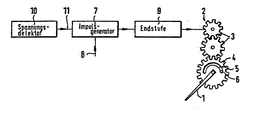
Ein Ausführungsbeispiel der Erfindung wird im folgenden anhand einer Zeichnung erläutert, in der der elektronische Teil für die Rückstellung der Analog-Anzeigeeinrichtung als Blockschaltbild dargestellt ist:
- In der Zeichnung ist mit 1 ein Zeiger eines elektronischen Tachometers dargestellt, der durch einen reversierbaren Schrittmotor angetrieben wird. Der Schrittmotor 2 steht über ein Getriebe 3 mit einem Zahnrad 4 in Verbindung, welches direkt mit dem Zeiger gekuppelt ist und um die gleiche Achse drehbar ist. Das Zahnrad 4 weist einen dem Endausschlag des Zeigers
proportionalen Ausschnitt 5 auf. Durch den Ausschnitt reicht ein ortsfester Anschlagstift 6, der in der in der Zeichnung dargestellten Drehstellung des Zahnrads 4 den Endanschlag in der Nullstellung bildet und an den entgegengesetzten Ende des Ausschnitts den Anschlag für Vollausschlag.
- In the drawing, 1 shows a pointer of an electronic tachometer which is driven by a reversible stepper motor. The stepper motor 2 is connected via a gear 3 to a gear 4 which is coupled directly to the pointer and can be rotated about the same axis. The gear wheel 4 has a
cutout 5 which is proportional to the end deflection of the pointer. A cut-out stop pin 6 extends through the cutout and, in the rotational position of the gear 4 shown in the drawing, forms the end stop in the zero position and at the opposite end of the cutout the stop for full deflection.
Zu der Anzeige der gefahrenen Geschwindigkeit des Fahrzeugs wird ein Impulsgenerator 7 über einen Steuereingang 8 so mit einem Geschwindigkeitssignal gesteuert, dass der Impulsgenerator einen die Geschwindigkeitsänderung nach Betrag und Grösse definierenden Puls an eine Endstufe 9 und von dieser an den Schrittmotor 2 abgibt. Durch diesen Vorgang ist die Stellung des Zeigers stets proportional der Geschwindigkeit.To display the speed of the vehicle being driven, a
Wird das Fahrzeug abgestellt, so wird die Unterbrechung der Spannung durch das Zündschloss durch einen Spannungsdetektor 10 erfasst. Der Spannungsdetektor gibt einen Rückstellbefehl in einen zweiten Steuereingang 11 des Impulsgenerators 7. Dadurch wird der Impulsgenerator veranlasst, eine konstante Impulszahl an die Endstufe 9 abzugeben, die so gross ist, dass der Zeiger auch aus der Vollausschlagstellung auf Null zurückgestellt wird. Dabei stösst in jedem Fall der Anschlagstift 6 an das der Nullstellung zugeordnete Ende des Ausschnitts 5 an. Dieser Puls wird aber nicht mit konstanter Frequenz abgegeben, sondern - da der Impulsgenerator einen Rampengenerator umfasst - in der Weise, dass die ersten Impulse mit einer Pulsfrequenz unterhalb der Start-Stop-Frequenz des Schrittmotors 2 erzeugt werden und erst die anschliessenden Impulse auf eine Pulsfrequenz oberhalb der Start-Stop-Frequenz hochlaufen. Damit läuft in jedem Fall der Schrittmotor 2 zuverlässig an, um auch bei Überwindung des Haftreibungsmoments in jedem Fall synchron zu der Impulszahl zurückgestellt zu werden Erst anschliessend wird die Geschwindigkeit der Rückstellung erhöht mit der erwünschten Folge, dass das Antriebsmoment des Schrittmotors abfällt, so dass der Ausschnitt 5 des Zahnrads 4 nur unter einem verhältnismässig geringen Motormoment an den Anschlagstift 6 angeschlagen wird. Da in den meisten Fällen in der Nullstellung des Zeigers noch weitere Impulse zur Rückstellung von dem Impulsgenerator abgegeben werden, wird der Zeiger in dieser Lage festgehalten, was ebenfalls erwünscht ist, da das Haltemoment des Schrittmotorsverhältnismässig gering ist.If the vehicle is parked, the interruption of the voltage by the ignition lock is detected by a
Die Pulsfrequenz, mit der die Impulse oberhalb der Start-Stop-Frequenz zur Rückstellung abgegeben werden, soll unterhalb der maximalen Betriebsfrequenz des Schrittmotors liegen, um den Schrittmotor in jedem Fall synchron zu den Impulsen anzutreiben.The pulse frequency at which the pulses are released for resetting above the start-stop frequency should be below the maximum operating frequency of the stepper motor in order to drive the stepper motor in any case synchronously with the pulses.
Claims (3)
Applications Claiming Priority (2)
| Application Number | Priority Date | Filing Date | Title |
|---|---|---|---|
| DE3145780 | 1981-11-19 | ||
| DE19813145780 DE3145780A1 (en) | 1981-11-19 | 1981-11-19 | ANALOG DISPLAY DEVICE, IN PARTICULAR SPEEDOMETER |
Publications (3)
| Publication Number | Publication Date |
|---|---|
| EP0080025A2 EP0080025A2 (en) | 1983-06-01 |
| EP0080025A3 EP0080025A3 (en) | 1985-08-21 |
| EP0080025B1 true EP0080025B1 (en) | 1987-10-14 |
Family
ID=6146684
Family Applications (1)
| Application Number | Title | Priority Date | Filing Date |
|---|---|---|---|
| EP82107422A Expired EP0080025B1 (en) | 1981-11-19 | 1982-08-16 | Analogue indicating device, particularly a tachometer |
Country Status (4)
| Country | Link |
|---|---|
| US (1) | US4475082A (en) |
| EP (1) | EP0080025B1 (en) |
| JP (1) | JPS5890121A (en) |
| DE (2) | DE3145780A1 (en) |
Families Citing this family (12)
| Publication number | Priority date | Publication date | Assignee | Title |
|---|---|---|---|---|
| US4567434A (en) * | 1981-11-19 | 1986-01-28 | Vdo Adolf Schindling Ag | Analog display device, particularly a tachometer |
| GB2184242B (en) * | 1985-11-13 | 1989-11-15 | Mitutoyo Mfg Co Ltd | Electronic measuring device |
| US4706008A (en) * | 1986-12-11 | 1987-11-10 | Ibm Corporation | Self-adjusting homing for a stepping motor |
| DE3701072C2 (en) * | 1987-01-16 | 1995-07-20 | Vdo Schindling | Pointer instrument |
| DE4018091A1 (en) * | 1990-06-06 | 1991-12-12 | Bosch Gmbh Robert | REDUCTION GEARBOX FOR DISPLAY INSTRUMENT |
| JP2524935Y2 (en) * | 1990-12-26 | 1997-02-05 | 矢崎総業株式会社 | Display device for vehicles |
| DE4310060C2 (en) * | 1992-03-28 | 1996-06-13 | Noris Tachometerwerk | Electrical analog display instrument with reset device |
| DE4403620B4 (en) * | 1994-02-05 | 2008-04-10 | Siemens Ag | pointer instrument |
| JP3048113B2 (en) * | 1995-01-11 | 2000-06-05 | 矢崎総業株式会社 | Needle-type display device and needle return method for needle-type display device |
| FR2732836B1 (en) * | 1995-04-07 | 1997-06-20 | Magneti Marelli France | STEPPER MOTOR DRIVE SYSTEM INCLUDING IMPROVED RESETTING MEANS |
| EP0769841B1 (en) * | 1995-10-20 | 2001-04-25 | Mannesmann VDO AG | Electromotor and measuring device, in particular for indicating instrument in vehicle |
| US6853162B2 (en) * | 2002-12-05 | 2005-02-08 | Visteon Global Technologies, Inc. | Re-zeroing of a stepper motor without noise or movement |
Family Cites Families (7)
| Publication number | Priority date | Publication date | Assignee | Title |
|---|---|---|---|---|
| US3512066A (en) * | 1967-03-08 | 1970-05-12 | Gerber Scientific Instr Co | Motor energizing system |
| US3818261A (en) * | 1971-12-23 | 1974-06-18 | Honeywell Inf Systems | Stepping motor speed control apparatus |
| US3886459A (en) * | 1973-08-07 | 1975-05-27 | Usm Corp | Digital pulse rate ramping circuits |
| DE2730699A1 (en) * | 1977-07-07 | 1979-01-18 | Vdo Schindling | DEVICE FOR DISPLAYING A MECHANICAL MEASURING SIZE, IN PARTICULAR THE SPEED OF A MOTOR VEHICLE |
| US4125801A (en) * | 1977-08-22 | 1978-11-14 | The Superior Electric Company | Presettable number to step motor control system |
| CH627906B (en) * | 1978-11-21 | Berney Sa Jean Claude | ANALOGUE DISPLAY DEVICE. | |
| DE2912362A1 (en) * | 1979-03-29 | 1980-10-16 | Rau Swf Autozubehoer | Vehicle speed or revolution rate indicating instrument - has indicator needle position motor and needle position slip contacts |
-
1981
- 1981-11-19 DE DE19813145780 patent/DE3145780A1/en not_active Ceased
-
1982
- 1982-08-16 DE DE8282107422T patent/DE3277467D1/en not_active Expired
- 1982-08-16 EP EP82107422A patent/EP0080025B1/en not_active Expired
- 1982-09-27 US US06/424,671 patent/US4475082A/en not_active Expired - Fee Related
- 1982-11-17 JP JP57200481A patent/JPS5890121A/en active Pending
Also Published As
| Publication number | Publication date |
|---|---|
| EP0080025A2 (en) | 1983-06-01 |
| DE3277467D1 (en) | 1987-11-19 |
| EP0080025A3 (en) | 1985-08-21 |
| DE3145780A1 (en) | 1983-05-26 |
| US4475082A (en) | 1984-10-02 |
| JPS5890121A (en) | 1983-05-28 |
Similar Documents
| Publication | Publication Date | Title |
|---|---|---|
| EP0080025B1 (en) | Analogue indicating device, particularly a tachometer | |
| DE2322368C3 (en) | Device for preventing the drive wheels of a motor vehicle driven by an internal combustion engine from spinning | |
| DE2357061C2 (en) | Device for the delivery of uniform pulses at certain angular positions of a rotatable shaft and for the formation of at least one reference signal | |
| DE2238827C3 (en) | Electronic clock with electronic time correction | |
| DE2205176C3 (en) | Circuit arrangement with a control for keeping the target speed of a direct current motor constant | |
| DE1703681C3 (en) | Screwdriver for the automatic tightening of screws | |
| DE2749006C3 (en) | Electronic correction device for a pendulum clock | |
| DE2852548C2 (en) | Digital tachometers, in particular for motor vehicles | |
| DE2730699A1 (en) | DEVICE FOR DISPLAYING A MECHANICAL MEASURING SIZE, IN PARTICULAR THE SPEED OF A MOTOR VEHICLE | |
| DE2124573C3 (en) | Device for the time control of the rifle flight on a loom | |
| DE2348026A1 (en) | METHOD AND DEVICE FOR BRAKING AND SWITCHING A HIGH-SPEED MACHINE MACHINE SPINDLE | |
| DE3441451C2 (en) | ||
| DE1805939A1 (en) | Weft search device | |
| DE2721240B2 (en) | Circuit arrangement for operating a stepper motor in the optimal load angle range | |
| DE2648341C2 (en) | Electronic encoder device | |
| DE3731097C2 (en) | Circuit arrangement for monitoring a device controlled by two microprocessors, in particular motor vehicle electronics | |
| EP0062928A1 (en) | Arrangement for generating a trigger pulse | |
| DE2500208A1 (en) | PULSE FREQUENCY SENSITIVE CHANGEOVER DEVICE | |
| DE3714201C2 (en) | ||
| WO1993012477A1 (en) | Process and arrangement for reducing vibrations caused by jolts in drives having mechanical arrangements capable of vibrating | |
| DE2850325C3 (en) | Time-keeping device, especially a large quartz clock with an electronically controlled display system | |
| DE1289871B (en) | Circuit arrangement for comparing a reference frequency pulse train with a signal frequency pulse train | |
| DD222172A1 (en) | DIGITAL-OVER-SPEED PROTECTION, ESPECIALLY FOR CENTRIFUGES | |
| DE1438819A1 (en) | Slip detector | |
| DE2166089C3 (en) | Method for operating a pulse-controlled stepper motor and circuit arrangement for carrying out the method |
Legal Events
| Date | Code | Title | Description |
|---|---|---|---|
| PUAI | Public reference made under article 153(3) epc to a published international application that has entered the european phase |
Free format text: ORIGINAL CODE: 0009012 |
|
| AK | Designated contracting states |
Designated state(s): DE FR GB NL SE |
|
| PUAL | Search report despatched |
Free format text: ORIGINAL CODE: 0009013 |
|
| AK | Designated contracting states |
Designated state(s): DE FR GB NL SE |
|
| 17P | Request for examination filed |
Effective date: 19850906 |
|
| 17Q | First examination report despatched |
Effective date: 19870130 |
|
| GRAA | (expected) grant |
Free format text: ORIGINAL CODE: 0009210 |
|
| AK | Designated contracting states |
Kind code of ref document: B1 Designated state(s): DE FR GB NL SE |
|
| ET | Fr: translation filed | ||
| REF | Corresponds to: |
Ref document number: 3277467 Country of ref document: DE Date of ref document: 19871119 |
|
| GBT | Gb: translation of ep patent filed (gb section 77(6)(a)/1977) | ||
| PLBE | No opposition filed within time limit |
Free format text: ORIGINAL CODE: 0009261 |
|
| STAA | Information on the status of an ep patent application or granted ep patent |
Free format text: STATUS: NO OPPOSITION FILED WITHIN TIME LIMIT |
|
| 26N | No opposition filed | ||
| PGFP | Annual fee paid to national office [announced via postgrant information from national office to epo] |
Ref country code: DE Payment date: 19890728 Year of fee payment: 8 |
|
| PG25 | Lapsed in a contracting state [announced via postgrant information from national office to epo] |
Ref country code: GB Effective date: 19890816 |
|
| PG25 | Lapsed in a contracting state [announced via postgrant information from national office to epo] |
Ref country code: SE Effective date: 19890817 |
|
| PG25 | Lapsed in a contracting state [announced via postgrant information from national office to epo] |
Ref country code: NL Effective date: 19900301 |
|
| NLV4 | Nl: lapsed or anulled due to non-payment of the annual fee | ||
| GBPC | Gb: european patent ceased through non-payment of renewal fee | ||
| PG25 | Lapsed in a contracting state [announced via postgrant information from national office to epo] |
Ref country code: FR Effective date: 19900427 |
|
| REG | Reference to a national code |
Ref country code: FR Ref legal event code: ST |
|
| PG25 | Lapsed in a contracting state [announced via postgrant information from national office to epo] |
Ref country code: DE Effective date: 19910501 |
|
| EUG | Se: european patent has lapsed |
Ref document number: 82107422.6 Effective date: 19900418 |