EP0079984B1 - Plastics trough - Google Patents
Plastics trough Download PDFInfo
- Publication number
- EP0079984B1 EP0079984B1 EP81110191A EP81110191A EP0079984B1 EP 0079984 B1 EP0079984 B1 EP 0079984B1 EP 81110191 A EP81110191 A EP 81110191A EP 81110191 A EP81110191 A EP 81110191A EP 0079984 B1 EP0079984 B1 EP 0079984B1
- Authority
- EP
- European Patent Office
- Prior art keywords
- tube
- trough
- ribs
- plastics material
- angle
- Prior art date
- Legal status (The legal status is an assumption and is not a legal conclusion. Google has not performed a legal analysis and makes no representation as to the accuracy of the status listed.)
- Expired
Links
Images


Classifications
-
- B—PERFORMING OPERATIONS; TRANSPORTING
- B65—CONVEYING; PACKING; STORING; HANDLING THIN OR FILAMENTARY MATERIAL
- B65D—CONTAINERS FOR STORAGE OR TRANSPORT OF ARTICLES OR MATERIALS, e.g. BAGS, BARRELS, BOTTLES, BOXES, CANS, CARTONS, CRATES, DRUMS, JARS, TANKS, HOPPERS, FORWARDING CONTAINERS; ACCESSORIES, CLOSURES, OR FITTINGS THEREFOR; PACKAGING ELEMENTS; PACKAGES
- B65D1/00—Containers having bodies formed in one piece, e.g. by casting metallic material, by moulding plastics, by blowing vitreous material, by throwing ceramic material, by moulding pulped fibrous material, by deep-drawing operations performed on sheet material
- B65D1/40—Details of walls
- B65D1/42—Reinforcing or strengthening parts or members
- B65D1/48—Reinforcements of dissimilar materials, e.g. metal frames in plastic walls
Definitions
- the invention relates to a bucket made of plastic, in particular for the transport and processing of ready-mixed mortar, of a truncated pyramid shape with an edge reinforcement made of a tube embedded in the plastic, which is bent at an obtuse angle in the region of the narrower side walls, the apex of which points upwards , and which is exposed in the area of the apex by two handle holes.
- Such a plastic bucket has become known from DE-PS-27 08 450.
- This bucket created for mortar has a fabric-reinforced plastic wall that fully encompasses the reinforcement frame made of steel in the circumferential direction of the frame parts, but leaves open areas of the frame on the end faces in the direction of extension of the frame parts that serve as eyelets for crane hooks or the like, with on the outside of the container reinforcing ribs are arranged.
- the production of fabric-reinforced plastic is very labor intensive. Therefore, such buckets are quite expensive to manufacture. The manufacture of such fabric-reinforced plastic buckets is not suitable for large-scale production.
- buckets according to DE-PS-11 49292 which have an edge reinforcement in the form of an annularly bent metal tube, which is completely surrounded by the plastic and have an impact at least at one point on their circumference, have proven effective, the ends of the metal tube being able to be inserted by means of an insertable interior -or a push-on outer sleeve are connected to each other.
- two opposing partial sections of the tube that forms the edge reinforcement are not overmolded, but are exposed and serve as handles or as attack surfaces for crane hooks.
- the invention improves the bucket of the type mentioned and solves the problem on which it is based in that the plastic is a polyolefin, in particular polyethylene, that the edge reinforcement is connected by two tube parts of the same shape in the middle of the long sides by two slipped sleeves that in the plastic surrounding the edge reinforcement is alternately arranged outside the sleeves, pairs of vertically radially directed holes on the pipe center and vertically extending slots tangentially adjacent to the pipe and that vertically downwardly extending short ribs are arranged on the edge of the handle holes, the width of which Corresponds to the width of the tube-reinforced edge.
- the plastic is a polyolefin, in particular polyethylene
- the edge reinforcement is connected by two tube parts of the same shape in the middle of the long sides by two slipped sleeves that in the plastic surrounding the edge reinforcement is alternately arranged outside the sleeves, pairs of vertically radially directed holes on the pipe center and vertically extending slots tangentially adjacent to the pipe and that vertically downwardly extending short ribs are
- Such a bucket can be cheaply produced as a mass-produced article by injection molding.
- the manual work involved is extremely low, it only consists of inserting the pipe and socket parts into the injection mold. These are precisely centered in the injection mold between pins, which are expressed in the edge reinforcement as holes which are directed radially vertically onto the tube means, and by means of projections in the shape, which are expressed as vertical slots in the plastic which are tangential to the side of the tube, so that the thickness of the plastic surrounding the steel pipe and the sleeves is the same everywhere. This is very important for the stability of the bucket.
- vertically downwardly extending short ribs are arranged on the edge of the handle holes, the width of which corresponds to the width of the tube-reinforced edge. These ribs prevent the pipe from being torn out of the surrounding plastic bed or the edge of the plastic from being torn open.
- the internal slot on the edge reinforcement has a base that is angled.
- the truncated pyramid-shaped bucket has longitudinal side walls 1, end side walls 2 and a bottom 3.
- the side walls 1, 2 are provided at the top with an edge reinforcement tube 4 and sleeves 5 including edge 6.
- the tubes 4 and the sleeves 5 are completely surrounded by plastic in the area of the long sides 1.
- the tubes 4 only emerge in a partial area of the side walls without plastic sheathing, in the area of the recesses 7 serving as hand or crane hook holes.
- the tube 4 is angled at an obtuse angle, preferably 40 °. The apex of this bend points upwards.
- the sleeves 5 connecting the two pipe parts 4 are arranged in the middle of the long sides.
- the bottom 3 has ribs 9 on the underside, the height of which is only small and suitably corresponds to the thickness of the wall material. These ribs have less of a reinforcing function than the function of preventing the soil material from being ground down when the bucket is being ground on the ground.
- the plastic casing 6 has holes 10 in the area of the edge reinforcement, which extend vertically and radially to the center of the tube 4. These holes come from pins in the injection mold, which were used for the horizontal centering of the tube 4 during the injection molding.
- the casing 6 also has slots 11 and 12, which also served to center the tube 4 in the injection mold during the injection molding process. These slots 11, 12 run essentially vertically and tangentially to the tube 4. They can be angular or rounded. They come from projections in the shape that were used to center the tube 4. After opening the injection mold, these holes and slots are used to check that the casing 6 around the pipe 4 is equally strong.
- the slot 12 has a base which is angled and encloses an angle of preferably 135 °. This bending ensures that the plastic of the wall merges seamlessly into the plastic of the casing. Centering holes can also be made where the sleeve 5 is located. These centering holes and centering slots 11, 12 are of great importance for the durability of the buckets because they ensure the uniform thickness of the plastic sheathing. These holes 10 and slots 11, 12 generally do not connect the tube 4 to the outside atmosphere because a very thin plastic skin has formed at the bottom of the holes 10 and the slots 11, 12 during the injection molding process.
- short ribs 13 are attached below the edge to the outside, which preferably have the same length as the ribs 8.
Abstract
Description
Die Erfindung betrifft einen Kübel aus Kunststoff, insbesondere für den Transport und die Verarbeitung von Fertigmörtel, von pyramidenstumpfförmiger Gestalt mit einer Randverstärkung aus einem in den Kunststoff eingebetteten Rohr, welches im Bereich der schmaleren Seitenwände unter einem stumpfen Winkel abgebogen ist, dessen Scheitel nach oben weist, und welches im Bereich des Scheitelpunktes durch zwei Handgrifflöcher frei liegt.The invention relates to a bucket made of plastic, in particular for the transport and processing of ready-mixed mortar, of a truncated pyramid shape with an edge reinforcement made of a tube embedded in the plastic, which is bent at an obtuse angle in the region of the narrower side walls, the apex of which points upwards , and which is exposed in the area of the apex by two handle holes.
Ein derartiger Kunststoffkübel ist aus der DE-PS-27 08 450 bekannt geworden. Dieser für Mörtel geschaffene Kübel weist eine gewebeverstärkte Kunststoffwandung auf, die den aus Stahl bestehenden Verstärkungsrahmen in Umfangsrichtung der Rahmenteile voll umgreift, an den Stirnseiten in Erstreckungsrichtung der Rahmenteile aber Bereiche des Rahmens freilässt, die als Ösen für Kranhaken oder dergleichen dienen, wobei an der Aussenseite des Behälters Verstärkungsrippen angeordnet sind. Die Herstellung aus gewebeverstärktem Kunststoff ist sehr arbeitsaufwendig. Daher werden solche Kübel in der Herstellung recht teuer. Die Herstellung solcher gewebeverstärkter Kunststoffkübel ist für eine Großserienfertigung nicht geeignet.Such a plastic bucket has become known from DE-PS-27 08 450. This bucket created for mortar has a fabric-reinforced plastic wall that fully encompasses the reinforcement frame made of steel in the circumferential direction of the frame parts, but leaves open areas of the frame on the end faces in the direction of extension of the frame parts that serve as eyelets for crane hooks or the like, with on the outside of the container reinforcing ribs are arranged. The production of fabric-reinforced plastic is very labor intensive. Therefore, such buckets are quite expensive to manufacture. The manufacture of such fabric-reinforced plastic buckets is not suitable for large-scale production.
Für die Großserienherstellung hingegen geeignet ist das Spritzgußverfahren, mit dem Kübel aus Kunststoff hergestellt werden können. Auf diese Weise wurde ein Kübel nach dem DE-GM-1854763 hergestellt, dessen Rand eine Umbördelung und unter der Umbördelung eine Wulst aufweist, über die ein geschlossener Ring gepreßt werden kann, der durch die Wulst einen festen Sitz zwischen der Wulst und der Umbördelung erhält. Derartig freiliegende Verstärkungsringe haben sich aber in der Praxis nicht bewährt, weil ein derartiger Kübel keine Ösen oder Handgrifflöcher aufweisen kann, ohne erheblich an Festigkeit zu verlieren.The injection molding process, with which buckets can be made of plastic, is suitable for large-scale production. In this way, a bucket was produced according to DE-GM-1854763, the edge of which has a beading and a bead under the beading, via which a closed ring can be pressed, which is given a firm fit between the bead and the beading by the bead . Such exposed reinforcement rings have not proven themselves in practice, however, because such a bucket cannot have eyelets or handle holes without losing considerable strength.
Bewährt hingegen haben sich Kübel nach DE-PS-11 49292, die eine Randverstärkung in Form eines ringförmig gebogenen Metallrohres aufweisen, welches vom Kunststoff völlig umgeben ist und mindestens an einer Stelle ihres Umfanges einen Stoß aufweisen, wobei die Enden des Metallrohres mittels einer einschiebbaren Innen-oder einer überschiebbaren Aussenmuffe miteinander verbunden sind. Bei diesem Kübel sind zwei einander gegenüberliegende Teilausschnitte des Rohres, das die Randverstärkung bildet, nicht umspritzt, sondern liegen frei und dienen als Griffe oder als Angriffsflächen von Kranhaken.On the other hand, buckets according to DE-PS-11 49292, which have an edge reinforcement in the form of an annularly bent metal tube, which is completely surrounded by the plastic and have an impact at least at one point on their circumference, have proven effective, the ends of the metal tube being able to be inserted by means of an insertable interior -or a push-on outer sleeve are connected to each other. In this bucket, two opposing partial sections of the tube that forms the edge reinforcement are not overmolded, but are exposed and serve as handles or as attack surfaces for crane hooks.
Probleme treten hier allerdings auf, wenn die Kübel eine pyramidenstumpfförmige Form haben. Dann ist merkwürdigerweise die Stabilität der Randverstärkung schlechter als bei kegelstumpfförmigen Kübeln. Pyramidenstumpfförmige Kübel werden aber gern für den Transport auf Transportfahrzeugen benutzt, weil dann die rechteckige Ladefläche der Transportfahrzeuge besser ausnutzbar ist.Problems arise here, however, if the buckets have a truncated pyramid shape. Then, strangely, the stability of the edge reinforcement is worse than that of truncated cones. However, truncated pyramid-shaped buckets are often used for transport on transport vehicles, because then the rectangular loading area of the transport vehicles can be better used.
Es ist die Aufgabe der Erfindung, einen billig als Massenartikel herstellbaren pyramidenstumpfförmigen Kübel zu schaffen, der sich durch hohe Stabilität und einfache Formgestaltung auszeichnet.It is the object of the invention to create a truncated pyramid-shaped bucket which is inexpensive to mass produce and which is distinguished by high stability and simple design.
Die Erfindung verbessert den Kübel der eingangs genannten Art und löst die ihr zugrunde liegende Aufgabe dadurch, daß der Kunststoff ein Polyolefin, insbesondere Polyäthylen, ist, daß die Randverstärkung aus zwei gleichgeformten Rohrteilen in der Mitte der Längsseiten durch zwei übergeschobene Muffen verbunden ist, daß in dem die Randverstärkung umgebenden Kunststoff ausserhalb der Muffen abwechselnd Paare von vertikal auf die Rohrmitte radial gerichteten Löchern und von vertikal verlaufenden, seitlich am Rohr tangential anliegenden Schlitzen angeordnet sind und daß am Rande der Handgrifflöcher vertikal sich nach unten erstreckende kurze Rippen angeordnet sind, deren Breite der Breite des rohrverstärkten Randes entspricht.The invention improves the bucket of the type mentioned and solves the problem on which it is based in that the plastic is a polyolefin, in particular polyethylene, that the edge reinforcement is connected by two tube parts of the same shape in the middle of the long sides by two slipped sleeves that in the plastic surrounding the edge reinforcement is alternately arranged outside the sleeves, pairs of vertically radially directed holes on the pipe center and vertically extending slots tangentially adjacent to the pipe and that vertically downwardly extending short ribs are arranged on the edge of the handle holes, the width of which Corresponds to the width of the tube-reinforced edge.
Ein solcher Kübel lässt sich billig als Massenartikel im Spritzgußverfahren herstellen. Hierbei aufzuwendende Handarbeit ist äusserst gering, sie besteht lediglich im Einlegen der Rohr- und Muffenteile in die Spritzgußform. Diese werden zwischen Stiften, die sich in der Randverstärkung als vertikal auf die Rohrmittel radial gerichtete Löcher abdrücken und durch Vorsprünge in der Form, die sich als vertikal verlaufende, seitlich am Rohr tangential anliegende Schlitze im Kunststoff abdrücken, genauestens in der Spritzgußform zentriert, so daß die Stärke des das Stahlrohr und die Muffen umgebenden Kunststoffes überall gleich ist. Das ist ganz wesentlich für die Stabilität des Kübels. Darüber hinaus sind am Rande der Handgrifflöcher vertikal sich nach unten erstreckende kurze Rippen angeordnet, deren Breite der Breite des rohrverstärkten Randes entspricht. Diese Rippen bewirken ein Verhindern des Ausreißens des Rohres aus dem umgebenden Kunststoffbett bzw. ein Aufreißen des Randes des Kunststoffes.Such a bucket can be cheaply produced as a mass-produced article by injection molding. The manual work involved is extremely low, it only consists of inserting the pipe and socket parts into the injection mold. These are precisely centered in the injection mold between pins, which are expressed in the edge reinforcement as holes which are directed radially vertically onto the tube means, and by means of projections in the shape, which are expressed as vertical slots in the plastic which are tangential to the side of the tube, so that the thickness of the plastic surrounding the steel pipe and the sleeves is the same everywhere. This is very important for the stability of the bucket. In addition, vertically downwardly extending short ribs are arranged on the edge of the handle holes, the width of which corresponds to the width of the tube-reinforced edge. These ribs prevent the pipe from being torn out of the surrounding plastic bed or the edge of the plastic from being torn open.
Mit diesem Kübel lässt sich Frischmörtel leicht auf Fahrzeugen und an Kranhaken transportieren. Die Kübel weisen eine hohe Lebensdauer auf, obwohl sie ohne Gewebeverstärkung hergestellt sind.With this bucket, fresh mortar can be easily transported on vehicles and on crane hooks. The buckets have a long lifespan, even though they are made without reinforcement.
Sie weisen auch keine am Boden angeordneten Tragtraversen parallel zur Kübelquerachse auf. Zweckmäßig ist es jedoch, unter dem Boden Rippen von der Stärke der Kübelwandungen anzuordnen, um zu verhindern, daß der Boden durch ein Schleifen beim Aufstellen an der Stellfläche mit der Zeit dünner wird. Diese Rippen dienen somit nicht so sehr der Verstärkung und Versteifung der Kübelform, sondern lediglich einer Verhinderung des Abschleifens des Bodenmaterials und einer Verhinderung des dadurch auftretenden Dünnerwerdens der Bodenwandung des Kübels.They also have no crossbeams arranged on the floor parallel to the transverse axis of the bucket. However, it is expedient to arrange ribs of the thickness of the bucket walls under the floor, in order to prevent the floor from becoming thinner over time due to grinding when it is set up on the standing surface. These ribs are therefore not so much used to reinforce and stiffen the bucket shape, but only to prevent the floor material from being ground down and to prevent the Bo from thinning as a result the wall of the bucket.
Zweckmäßig ist es, wenn an den Längsseitenwänden je ein Paar sich vertikal nach unten erstrekkender Rippen angeordnet ist, deren Länge und Breite den Rippen neben den Handgrifflöchern entspricht.It is useful if a pair of vertically downward extending ribs is arranged on the longitudinal side walls, the length and width of which correspond to the ribs next to the handle holes.
Zweckmäßig ist es, wenn der innen liegende Schlitz an der Randverstärkung eine Grundfläche aufweist, die abgewinkelt ist.It is useful if the internal slot on the edge reinforcement has a base that is angled.
Das Wesen der Erfindung ist nachstehend anhand eines in der Zeichnung schematisch dargestellten Ausführungsbeispieles näher erläutert. Es zeigen :
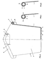
Figur 1 eine Ansicht auf die Längsseite des Kübels, im rechten Teil geschnitten,Figur 2 eine Ansicht auf die Stirnseite des Kübels, in der rechten Hälfte geschnitten,Figur 3 eine Ansicht von oben auf ein Eckteil des Kübels,Figur 4 einen Schnitt durch die Randverstärkung längs der Linie A-A,Figur 5 einen Schnitt durch die Randverstärkung längs der Ebene B-B.
- FIG. 1 shows a view of the long side of the bucket, cut in the right part,
- FIG. 2 shows a view of the front of the bucket, cut in the right half,
- FIG. 3 shows a view from above of a corner part of the bucket,
- FIG. 4 shows a section through the edge reinforcement along the line AA,
- Figure 5 shows a section through the edge reinforcement along the plane BB.
Der pyramidenstumpfförmige Kübel weist Längsseitenwände 1, Stirnseitenwände 2 und einen Boden 3 auf. Die Seitenwände 1, 2 sind oben mit einem Randverstärkungsrohre 4 und Muffen 5 umfassenden Rand 6 versehen. Die Rohre 4 und die Muffen 5 sind im Bereich der Längsseiten 1 völlig vom Kunststoff umgeben. Die Rohre 4 treten lediglich in einem Teilbereich der Seitenwände ohne Kunststoffummantelung hervor, und zwar im Bereich der als Hand- oder Kranhakenlöcher dienenden Ausnehmungen 7. Zu beiden Seiten dieser Ausnehmungen 7 befindet sich eine kurze, nach unten gerichtete Rippe 8, die eine Verstärkung der Kunststoffummantelung 6 im Bereich des Randes darstellt. Durch diese Rippen 8 wird ein Ausreißen der Kunststoffummantelung 6 dort verhindert, wo das Rohr 4 aus der Kunststoffummantelung 6 heraustritt. In der Mitte des Handgriff- bzw. Kranhakenloches 7 ist das Rohr 4 um einen stumpfen Winkel, vorzugsweise 40°, abgewinkelt. Der Scheitel dieser Abwinkelung weist nach oben. Die die beiden Rohrteile 4 miteinander verbindenden Muffen 5 sind in der Mitte der Längsseiten angeordnet.The truncated pyramid-shaped bucket has
Der Boden 3 weist auf der Unterseite Rippen 9 auf, deren Höhe nur gering ist und zweckmäßigerweise der Stärke des Wandungsmateriales entspricht. Diese Rippen haben weniger eine Verstärkungsfunktion als vielmehr die Funktion zu verhindern, daß beim Schleifen des Kübels auf dem Boden das Bodenmaterial abgeschliffen wird.The
Wie aus den Fig. 3 bis 5 am besten ersichtlich, weist die Kunststoffummantelung 6 im Bereich der Randverstärkung Löcher 10 auf, die sich vertikal und radial zur Mittel des Rohres 4 erstrecken. Diese Löcher stammen von Stiften in der Spritzgußform, die der horizontalen Zentrierung des Rohres 4 während des Spritzgießens dienten. Neben diesen Paaren von Löchern 10 in der Ummantelung 6 weist die Ummantelung 6 noch Schlitze 11 und 12 auf, die ebenfalls während des Spritzvorganges zur Zentrierung des Rohres 4 in der Spritzgußform gedient hatten. Diese Schlitze 11, 12 verlaufen im wesentlichen vertikal und tangential zum Rohr 4. Sie können eckig oder gerundet sein. Sie stammen von Vorsprüngen in der Form, die der Zentrierung des Rohres 4 dienten. Diese Löcher und Schlitze dienen nach dem Öffnen der Spritzgußform zur Kontrolle dafür, daß die Ummantelung 6 um das Rohr 4 überfall gleich stark ist.As can best be seen from FIGS. 3 to 5, the
Der Schlitz 12 weist eine Grundfläche auf, die abgewinkelt ist und eine Winkel von vorzugsweise 135° einschließt. Durch diese Abwinkelung ist erreicht, daß nahtlos der Kunststoff der Wandung in den Kunststoff der Ummantelung übergeht. Zentrierlöcher können auch dort angebracht sein, wo sich die Muffe 5 befindet. Diese Zentrierlöcher und Zentrierschlitze 11, 12 sind für die Haltbarkeit der Kübel von großer Wichtigkeit, weil durch sie die überall gleichmäßige Stärke der Kunststoffummantelung gesichert ist. Diese Löcher 10 und Schlitze 11, 12 verbinden im allgemeinen nicht das Rohr 4 mit der Aussenatmosphäre, weil sich während des Spritzgußvorganges am Boden der Löcher 10 und der Schlitze 11, 12 ein sehr dünnes Kunststoffhäutchen ausgebildet hat.The
An den Längsseiten sind unterhalb des Randes nach aussen zu noch kurze Rippen 13 angebracht, welche vorzugsweise die gleiche Länge wie die Rippen 8 aufweisen.On the long sides,
Claims (4)
Priority Applications (1)
| Application Number | Priority Date | Filing Date | Title |
|---|---|---|---|
| AT81110191T ATE12920T1 (en) | 1981-11-25 | 1981-12-05 | PLASTIC BUCKET. |
Applications Claiming Priority (2)
| Application Number | Priority Date | Filing Date | Title |
|---|---|---|---|
| DE3146685 | 1981-11-25 | ||
| DE3146685A DE3146685A1 (en) | 1981-11-25 | 1981-11-25 | "PLASTIC PLASTIC" |
Publications (3)
| Publication Number | Publication Date |
|---|---|
| EP0079984A2 EP0079984A2 (en) | 1983-06-01 |
| EP0079984A3 EP0079984A3 (en) | 1983-06-29 |
| EP0079984B1 true EP0079984B1 (en) | 1985-04-24 |
Family
ID=6147169
Family Applications (1)
| Application Number | Title | Priority Date | Filing Date |
|---|---|---|---|
| EP81110191A Expired EP0079984B1 (en) | 1981-11-25 | 1981-12-05 | Plastics trough |
Country Status (3)
| Country | Link |
|---|---|
| EP (1) | EP0079984B1 (en) |
| AT (1) | ATE12920T1 (en) |
| DE (2) | DE3146685A1 (en) |
Families Citing this family (1)
| Publication number | Priority date | Publication date | Assignee | Title |
|---|---|---|---|---|
| GB2143479B (en) * | 1983-07-11 | 1987-02-18 | Glasdon Ltd | Improvements in or relating to bins |
Family Cites Families (3)
| Publication number | Priority date | Publication date | Assignee | Title |
|---|---|---|---|---|
| DE1149292B (en) * | 1960-01-25 | 1963-05-22 | Friedrich Stuckenbroeker | Edge reinforcement for transport containers made of plastic |
| FR1379277A (en) * | 1963-12-26 | 1964-11-20 | Cogindus | Bin for handling or other uses |
| DE2708450C3 (en) * | 1977-02-26 | 1980-12-11 | Staba Handels- Und Transportgesellschaft Mbh, 4720 Beckum | Transport container for mortar |
-
1981
- 1981-11-25 DE DE3146685A patent/DE3146685A1/en not_active Withdrawn
- 1981-12-05 AT AT81110191T patent/ATE12920T1/en not_active IP Right Cessation
- 1981-12-05 EP EP81110191A patent/EP0079984B1/en not_active Expired
- 1981-12-05 DE DE8181110191T patent/DE3170197D1/en not_active Expired
Also Published As
| Publication number | Publication date |
|---|---|
| EP0079984A3 (en) | 1983-06-29 |
| DE3170197D1 (en) | 1985-05-30 |
| DE3146685A1 (en) | 1983-06-01 |
| EP0079984A2 (en) | 1983-06-01 |
| ATE12920T1 (en) | 1985-05-15 |
Similar Documents
| Publication | Publication Date | Title |
|---|---|---|
| DE2437809C3 (en) | Sieve bottom as well as sieve bodies and frames therefor | |
| EP0009764B1 (en) | Cover-belt conveyor | |
| EP0515819A2 (en) | Transport and storage container | |
| DE2306869A1 (en) | PLASTIC PALLET | |
| CH672295A5 (en) | ||
| EP0371917A1 (en) | Capping frame for a drainage channel | |
| CH651730A5 (en) | SUITCASE. | |
| DE2200512C3 (en) | Spacers for reinforcing bars | |
| DE2549400C3 (en) | Plastic container | |
| DE2703721C2 (en) | Plastic buckets | |
| EP0079984B1 (en) | Plastics trough | |
| CH648368A5 (en) | ROAD EDGE POST. | |
| EP0080197B1 (en) | Plastics trough | |
| DE2805880A1 (en) | SPROCKET | |
| EP0329001A1 (en) | Device for removing debris and similar bulk material | |
| DE3402046A1 (en) | Process and device for producing a grate-shaped plastic grid element as well as grate element made of plastic | |
| DE202007002790U1 (en) | Synchronization device for lifting devices | |
| WO1988000915A1 (en) | Collection tank for reusable product | |
| DE2317594C3 (en) | Cheese mold for making cheese with a dense cheese rind, in particular for making pressed cheese | |
| DE19738649A1 (en) | Subsurface garden storage unit made from a series of stacked rings | |
| EP1502996B1 (en) | Grid plate | |
| EP0361002B1 (en) | Container, especially a compost container | |
| DE8134335U1 (en) | Plastic bucket | |
| DE2819392A1 (en) | Interlocking retaining wall building block - has staggered knuckles on vertical hinge edges and angled base plate tapering towards open end | |
| EP1198396A1 (en) | Large volume container for holding liquid media |
Legal Events
| Date | Code | Title | Description |
|---|---|---|---|
| PUAI | Public reference made under article 153(3) epc to a published international application that has entered the european phase |
Free format text: ORIGINAL CODE: 0009012 |
|
| PUAL | Search report despatched |
Free format text: ORIGINAL CODE: 0009013 |
|
| AK | Designated contracting states |
Designated state(s): AT BE CH DE FR GB IT LI LU NL SE |
|
| AK | Designated contracting states |
Designated state(s): AT BE CH DE FR GB IT LI LU NL SE |
|
| 17P | Request for examination filed |
Effective date: 19830829 |
|
| ITF | It: translation for a ep patent filed |
Owner name: DOTT. FRANCO CICOGNA |
|
| GRAA | (expected) grant |
Free format text: ORIGINAL CODE: 0009210 |
|
| AK | Designated contracting states |
Designated state(s): AT BE CH DE FR GB IT LI LU NL SE |
|
| REF | Corresponds to: |
Ref document number: 12920 Country of ref document: AT Date of ref document: 19850515 Kind code of ref document: T |
|
| REF | Corresponds to: |
Ref document number: 3170197 Country of ref document: DE Date of ref document: 19850530 |
|
| ET | Fr: translation filed | ||
| PG25 | Lapsed in a contracting state [announced via postgrant information from national office to epo] |
Ref country code: LU Free format text: LAPSE BECAUSE OF NON-PAYMENT OF DUE FEES Effective date: 19851231 |
|
| PLBE | No opposition filed within time limit |
Free format text: ORIGINAL CODE: 0009261 |
|
| STAA | Information on the status of an ep patent application or granted ep patent |
Free format text: STATUS: NO OPPOSITION FILED WITHIN TIME LIMIT |
|
| 26N | No opposition filed | ||
| PGFP | Annual fee paid to national office [announced via postgrant information from national office to epo] |
Ref country code: AT Payment date: 19861215 Year of fee payment: 6 |
|
| PGFP | Annual fee paid to national office [announced via postgrant information from national office to epo] |
Ref country code: NL Payment date: 19861231 Year of fee payment: 6 |
|
| PG25 | Lapsed in a contracting state [announced via postgrant information from national office to epo] |
Ref country code: AT Effective date: 19871205 |
|
| PG25 | Lapsed in a contracting state [announced via postgrant information from national office to epo] |
Ref country code: SE Effective date: 19871206 |
|
| PG25 | Lapsed in a contracting state [announced via postgrant information from national office to epo] |
Ref country code: LI Effective date: 19871231 Ref country code: CH Effective date: 19871231 Ref country code: BE Effective date: 19871231 |
|
| BERE | Be: lapsed |
Owner name: STUCKI KUNSTSTOFFWERK UND WERKZEUGBAU G.M.B.H. Effective date: 19871231 |
|
| PG25 | Lapsed in a contracting state [announced via postgrant information from national office to epo] |
Ref country code: NL Effective date: 19880701 |
|
| NLV4 | Nl: lapsed or anulled due to non-payment of the annual fee | ||
| GBPC | Gb: european patent ceased through non-payment of renewal fee | ||
| PG25 | Lapsed in a contracting state [announced via postgrant information from national office to epo] |
Ref country code: FR Free format text: LAPSE BECAUSE OF NON-PAYMENT OF DUE FEES Effective date: 19880831 |
|
| REG | Reference to a national code |
Ref country code: CH Ref legal event code: PL |
|
| PG25 | Lapsed in a contracting state [announced via postgrant information from national office to epo] |
Ref country code: DE Effective date: 19880901 |
|
| REG | Reference to a national code |
Ref country code: FR Ref legal event code: ST |
|
| PG25 | Lapsed in a contracting state [announced via postgrant information from national office to epo] |
Ref country code: GB Free format text: LAPSE BECAUSE OF NON-PAYMENT OF DUE FEES Effective date: 19881121 |
|
| EUG | Se: european patent has lapsed |
Ref document number: 81110191.4 Effective date: 19880912 |