EP0079795A2 - Pneumatischer Lungensimulator - Google Patents
Pneumatischer Lungensimulator Download PDFInfo
- Publication number
- EP0079795A2 EP0079795A2 EP82306084A EP82306084A EP0079795A2 EP 0079795 A2 EP0079795 A2 EP 0079795A2 EP 82306084 A EP82306084 A EP 82306084A EP 82306084 A EP82306084 A EP 82306084A EP 0079795 A2 EP0079795 A2 EP 0079795A2
- Authority
- EP
- European Patent Office
- Prior art keywords
- test
- ventilator
- movable wall
- frame
- chamber
- Prior art date
- Legal status (The legal status is an assumption and is not a legal conclusion. Google has not performed a legal analysis and makes no representation as to the accuracy of the status listed.)
- Granted
Links
Images


Classifications
-
- G—PHYSICS
- G09—EDUCATION; CRYPTOGRAPHY; DISPLAY; ADVERTISING; SEALS
- G09B—EDUCATIONAL OR DEMONSTRATION APPLIANCES; APPLIANCES FOR TEACHING, OR COMMUNICATING WITH, THE BLIND, DEAF OR MUTE; MODELS; PLANETARIA; GLOBES; MAPS; DIAGRAMS
- G09B23/00—Models for scientific, medical, or mathematical purposes, e.g. full-sized devices for demonstration purposes
- G09B23/28—Models for scientific, medical, or mathematical purposes, e.g. full-sized devices for demonstration purposes for medicine
Definitions
- This invention relates generally to pneumatic lung analogs and more particularly, is directed to a pneumatic lung analog capable of testing ventilatory devices intended for use with spontaneously breathing patients.
- ventilatory devices may be divided into two categories: devices intended to support apneic (non-spontaneously breathing) patients, commonly termed control ventilation; and devices intended to be used in conjunction with spontaneously breathing patients. Frequently, a single device may provide modes of operation covering both categories of use.
- This invention deals specifically with the testing of ventilatory devices which are intended to be used (or have such operational modes) with spontaneously breathing patients. Examples of such equipment include demand oxygen inhalation devices, "assist" ventilators, and intermittent mandatory ventilation (IMV) devices.
- IMV intermittent mandatory ventilation
- the patient provides a small continuous negative pressure signal to the device produced by his inhalation, and this signal automatically provides a flow of oxygen to the patient until he begins to exhale, at which time the pressure signal reverses from negative to positive.
- the patient must maintain a slight negative pressure within the device, and this requirement, in effect, imposes an additional breathing work load on the patient which is of concern.
- the disadvantage if small, can be significantly outweighed by the attendant advantages of enriched oxygen breathing, and the "on demand" feature conserves the supply of oxygen.
- “Assist” ventilators are designed to be triggered by the patient's initial spontaneous breathing effort. After sensing an initial negative airway pressure or flow produced by the patient, then such a device applies positive pressure to the patient for the inspiration of breathing gas. During such inspiration, no effort is required by the patient. Termination of each inspiration is automatic, and may depend on time, delivered volume, or pressure. In testing this type of device, the demand made on the patient is to trigger it to an "on" state is of concern, and involves a knowledge of peak negative pressure needed, flow, response time, and added work of breathing.
- Intermittent Mandatory Ventilators are so termed because they intermittently and automatically apply pressurized.gas to the patient at preset intervals. However, between such intermittent machine breaths, the patient is expected to breath through the device spontaneously. During these periods, the breathing gas is preferably conditioned as needed by the patient (for example, oxygen and humidity may be added, and the temperature controlled); also, instead of allowing the patient to exhale fully down to atmospheric pressure, a low pressure plateau of up to 30 cm. H 2 0 pressure above atmospheric, is frequently maintained. This is called constant positive airway pressure (CPAP) and is very useful under certain conditions in treating patients with pulmonary disease.
- CPAP constant positive airway pressure
- IMV ventilators incorporate servo mechanisms to reduce this work of breathing, but in all cases the patient must generate a small sub-atmoshperic (or sub-CPAP) pressure in order to cause gas.flow, and this always causes some additional work of breathing. This added work of breathing is of concern in the testing of IMV ventilators.
- Pneumatic lung analogs for testing ventilators are known in the prior art. Such machines must be capable, through adjustment, of simulating a wide range of patient pulmonary physiology, ranging from pediatric to large, adult patients with various types and states of pulmonary disease.
- One such device is the training test.lung described in U.S. Reissue Patent 29,317 reissued July 26, 1977 to Mosley et al.
- the training test lung described in U.S. Re-29,317 simulates human.lungs by providing a pair of expansible chambers or bellows which are secured..at one end to a frame and at the other end to a pair of movable end plates.
- the bellows are interconnected by a Y-shaped fitting to assistant ventilation equipment for inflation.
- the movable end plates pivot relative to .the frame as the bellows are inflated and the free end of the pivotable plate cooperates with printed indicia on a panel adjacent thereto, to provide a visual readout of the inspired tidal volume.
- Pulmonary compliance is simulated by adjustable springs which interconnect the pivotable plates and the stationary frame.
- Respiratory flow resistance is simulated by calibrated flow resistant tubes disposed in the flow path extending between the expansible bellows and the assistant ventilator.
- control ventilators apply positive pressure to inflate the patient's lungs, when a patient is being treated by a control ventilator,the actual work of breathing is.being carried out by the ventilator. This sometimes creates a problem since, with the extended periods of assisted ventilation, the patient begins to lose the ability to generate the work of breathing himself. Such patients often become quite dependent upon the ventilator and it may become difficult to wean these patients away from the ventilator. This problem led to the development of ventilators capable of carrying out intermittent mandatory ventilation. The newer IMV ventilators solve this problem by allowing a patient that is not apneic to breathe spontaneously whenever possible.
- Such a patient may be breathing weakly, erratically, or undependably, but there are advantages to allowing such a patient to generate the work of breathing himself whenever possible.
- a ventilator provides a pathway for the patient to breathe through on his own.
- ventilators also periodically apply a positive airway pressure to create a mandatory breath.
- This type of ventilator can protect a patient who is capable of becoming apneic, and can be used to wean a patient away from assisted ventilation.
- an IMV ventilator is used with a patient that is capable of accomplishing the work of breathing himself, the added work of breathing created by the ventilator, is of course, critical to the success of the treatment.
- a pneumatic lung analog for testing a ventilator comprises: a frame; a test ventilator expansible chamber disposed on said frame for receiving the output of a test ventilator; a movable wall disposed on said test expansible chamber; means for pulling said movable wall and thus simulating human lungs in spontaneous breathing; and means for providing a measure of the pressure and volume of air supplied to said test expansible chamber by a ventilator when said means for pulling is activated,.whereby the function of the ventilator is quantitatively determined.
- the pulling means comprises a spontaneous breath generator expansible chamber disposed on said frame for receiving the output of a spontaneous breath generator, a movable spontaneous breath end plate disposed on said spontaneous breath expansible chamber, and means interconnecting the end plate to the movable wall to provide for the concurrent motion thereof.
- portions of the pneumatic lung analog may, for example, comprise an older training test lung of the type used to test control ventilators. Since the training test lung is provided with two movable end plates connected to first and second expansible bellows for independent movement therewith, a coupler extending between the end plates is required.
- the spontaneous breath generator may, for example, comprise a standard volume ventilator which is connected to one of the expansible bellows of the training test lung.
- the volume ventilator drives the spontaneous breath expansible chamber with air at pressures required to simulate a typical human spontaneous breath in the test ventilator chamber, which expands therewith due to the coupler.
- the expanding test ventilator chamber thus simulates a spontaneously breathing patient and draws in inspired gas by creation of a sub-ambient pressure (negative pressure) within it.
- the ventilator which is connected to the test ventilator chamber senses the negative pressure generated by the expanding test ventilator chamber and supplies ventilatory gas to the chamber, as it would to a breathing patient.
- the ventilatory cycle of the spontaneous breath generator can be varied to simulate the varying demands which a patient may place on a ventilator, or it may be preset to a typical, average patient condition.
- the added work of breathing imposed by breathing through the ventilator during those portions of the ventilatory cycle when a spontaneously breathing patient is simulated, is measured by a transducer which monitors sub-ambient pressure created within the airway or the patient connection of the test ventilator, along with means for determining the instantaneous volume of gas inhaled by the test ventilator chamber.
- the added worl. of breathing is then represented by the mathematical integral of pressure relative to volume over a complete breathing cycle.
- a portion of a pneumatic lung analog according to the invention may be provided by a known pneumatic lung analog and accordingly the invention provides, according to a second aspect, a kit for modifying a pneumatic lung analog of the-type having a frame, first and second expansible chambers disposed on said frame for simulating human lungs and first and second movable end plates mounted on said chambers, said kit modifying said lung analog to provide a device capable of testing a ventilator of the type used with spontaneously breathing patients, said kit comprising: means for interconnecting said first and second movable end plates to provide for the concurrent movement thereof when the output of a spontaneous breath generator is connected to one of said chambers to provide a spontaneous breath chamber and said ventilator is connected to the other of said chambers to provide a test chamber; and means for providing a measure of the pressure and volume of air applied to said test chamber by said ventilator, whereby the added work of breathing through the said ventilator is determined.
- a pneumatic lung analog 10 comprises a frame 11 having a test ventilator expansible chamber, or lung simulator expansible chamber, 12 and a spontaneous breath generator expansible chamber 13 disposed thereon.
- the test ventilator chamber 12 receives the output of a test ventilator on line 15 and the spontaneous breath chamber 13 receives the output of a spontaneous breath generator on line 16.
- the spontaneous breath generator illustrated in block form at 18 in Figure 1 may, for example, comprise a volume ventilator of the type well known in the art.
- the resistance into and the compliance of test ventilator chamber 12 is set to simulate the flow resistance and compliance of a pair of human lungs.
- a movable end plate 20 is disposed on the ventilator test chamber 12 and the spontaneous breath chamber 13 for concurrent movement therewith when one of the chambers are-inflated.
- the plate 20 may comprise one continuous generally planar member; however., it has been found preferable to modify an older training test lung which has two movable plates.
- the movable end plate comprises a movable test ventilator end plate 21 :and a movable spontaneous breath end plate 22.
- the test ventilator chamber 12 and the spontaneous breath chamber .13 are disposed between the frame 11 and the movable ventilator test plate 21 and the movable spontaneous breath plate 22, respectively.
- a coupler, or means for interconnecting, is disposed at 25 between the two end plates to ensure the concurrent motion of the two plates.
- the coupler 25 comprises a hinged connection and the movable plates 21 and 22 are pivotable about a common axis 28.
- the pivot axis 29 of the coupler 25 extending between the movable plates 21 and 22 is orthogonal to the pivot axis 28 of the movable plates.
- the added work of breathing imposed by the test ventilator is determined by calculating: Where P equals sub-ambient airway pressure created by the patient's spontaneous breath, and V equals the instantaneous volume of air supplied to the test ventilator chamber 12, simulating the patient's lungs.
- Means are provided for providing a measure of the pressure and volume of air applied to the test ventilator chamber comprising a transducer 35 for measuring pressure and a variable electrical resistance 36 for measuring the angular displacement of the test ventilator end plate 21.
- the outputs of these transducers are inputted to an analyzing means at 40.
- the analyzing means 40 may comprise a programmable digital processor, a micro-processor, or an X-Y recorder. In the case of an X-Y recorder, the area of the curve plotted by the X -Y recorder at 40 is representative of the added work of breathing through the test ventilator.
- the computer is responsive to data inputs such as pressure and volume, to evaluate for example, the function W as set out in Equation (1) over a single breath cycle, and to present W as a computed value automatically. This could'be done on an analog or digital basis, and the computer also could be utilized to provide and read out other test data, such as peak negative pressure, response time, etc.
- a flow resistor 42 is normally disposed between the transducer 35 and the test chamber 12 to simulate the flow resistance of. the respiratory tract of a patient.
- the flow-resistance may,. for example, be a tube or the like of a known cross-sectional area which creates a predetermined flow resistance.
- the natural resilience of the human lung is simulated by tension springs 48 and 49 which interconnect the movable end plates and the stationary frame 11. Normally, the tension spring 48 would be set to the compliance value desired to simulate the human patient., and the tension spring 49 would be set over pivot axis 28.
- the end plate 20 may, for example, be one continuous planar plate.
- the end plate 20 need not be pivotable about one end as long as an equivalent mechanical arrangement is provided for ensuring translational, parallel displacement.
- a single plate may be provided which engages just one of the expansible chambers. An arm disposed on the single plate may then engage the other expansible chamber. Pivoting of the end plate 2 0 about a generally horizontal axis 28 is regarded as one of the most expedient means for achieving this goal, even though some torsional distortion of the plates may occur, requiring a hinged coupler, and compensating corrections to the tidal volume scales.
- variable electrical resistance 36 is used for measuring the angular displacement of the movable end plate 20
- other approaches for determining the volume of air introduced to the test ventilator chamber 12 are conceivable.
- the change in pressure encountered on opposite sides of the flow restrictor 42 could be used as a measure of the flow of air supplied to the test ventilator chamber 12. This flow measurement could then be integrated relative to time to define instantaneous volume.
- the pneumatic lung analog being described is a modification of the training test lung described in U.S. Re-29,317.
- the training.test lung is an item that .has been commercially available for some time and thus, in its most basic form, the present invention may comprise a kit for modifying the training test lung.
- a kit for modifying the training test lung Such a kit would include means for connecting one of the chambers of the training test lung to a spontaneous breath generator and connecting the other chamber to a test ventilator.
- a conventional volume ventilator which is normally on hand may be used to drive the spontaneous breath chamber, or a special spontaneous breath generator may be supplied as part of the kit.
- the kit also includes a hinged coupler to provide for the concurrent motion of the two end plates and also includes means for providing a measure of the pressure and volume of air applied to the test ventilator expansible chamber such that the added work of breathing imposed by the test ventilator can be determined.
- the training test lung comprises a pair of expansible chambers arranged in mutual association with a pair of movable end plates to simulate a pair of lungs.
- each of the bellows and end plates are individually provided with sufficient capacity and controlled restraint to simulate the compliance of a normal adult pair of lungs.
- the movable end plates operate independently and are separately..-adjustable in terms.of the flow resistance and resiliency simulated.
- a hinged coupler 25 comprising first and second generally U-shaped clamps 50 and.51 which engage the spontaneous breath and test ventilator end plates 22 and 21, respectively.
- Each of the clamps 50 and 51 is provided with a thumb-actuated set screw 53.
- a hinge 55 defining a pivot axis 29 extends between the clamps 50 and 51.
- the coupler 25 is mounted between the movable plates of the training test lung and oriented such that the pivot axis of the hinge 55 is orthogonal to the pivot axis 28 of the movable end plates.
- connection is made near the free end of the movable end plates 21 and 22 to minimize flexing of the free ends of the end plates. While a pivotable connection is preferred, other types of connections may prove satisfactory. Such connections might involve the use of a simple lift bar which is secured to the spontaneous breath plate and which extends under the test ventilator end plate for lifting the same when a spontaneous breath is applied to the spontaneous.breath expansible chamber.
- the pressure transducer 35 may comprise any one of a number of commercially available in-line pressure transducers having an output compatible with X-Y recorder 40. With specific reference to Figures 6 and 7, the preferred embodiment of the transducer which provides a measure of the volume of air applied to the test ventilator expansible chamber, is illustrated.
- the volume transducer preferably comprises a variable resistance 36 which monitors the angular displacement of the test ventilator plate 21.
- the variable resistance 36 is provided with a cylindrical body.60 having a pivotable shaft 61 extending therefrom.
- the pivotable or rotatable shaft 61 is connected to the movable test ventilator end plate 21 along an axis which is colinear with the pivot axis 28 of the test ventilator plate 21.
- the cylindrical body 60 of the resistor is connected to a frame member 62 via a split ring clamp 64, which encompasses the cylindrical body 60 of the resistor 36, and an arm 65.
- the arm 65 includes the U-shpaed clamp and set screw generally indicated at 66 for attaching the same to the frame member 62. Rotation of the shaft 61 varies the effective resistance value of the resistor 36.
- the effective resistance of the resistor varies as a function of the angular displacement of the movable end plate 21, and this provides an accurate measure of the volume of gas introduced into the test ventilator expansible chamber.
- Means are provided for coupling the pivotable shaft 61 to the test ventilator end plate 21, comprising a generally U-shaped bracket 70 which encompasses the test ventilator end plate 21.
- the bracket 70 includes first and second sockets 71 and 72 which,.encompass opposing ends of a pivot shaft 73 about which the movable test ventilator plate 21 is journalled.
- the U-shaped bracket 70 is preferably of a three-piece construction comprising a tying strap 75 and end brackets 76 and 77.
- the end brackets 76 and 77 contain the sockets 71 and 72, respectively.
- the end brackets 76 and 77 are detachable or movable with respect to the.typing strap 75 to permit mounting of the sockets 71 and 72 over the ends of the pivot shaft 73.
- the end brackets 76 and 77 are disposed on opposing sides of the movable test ventilator plate 21 with the sockets 71 and 72 encompassing the ends of the pivot shaft 73. Thereafter, the typing strap 75 is connected thereto with a first pair of thumb-actuated set screws at 78. A second pair of thumb-actuated set screws are provided at 80 for engaging the test ventilator plate 21 and removing any lost motion between.-the generally U-shaped bracket 70 and the test ventilator plate 21.
- the end bracket 76 also includes a socket 82 for receiving the rotatable shaft 61 of the resistor 36 in a relationship colinear with the axi.s 28 of the pivot shaft 73.
- a set screw at 81 rigidly connects the rotatable shaft 61 for concurrent pivotal movement along with the U-shaped bracket 75 and the test ventilator plate 21.
- a split ring connector 64 is used to connect the cylindrical body 60 of the resistor 36 to stationary arm 65 to permit zeroing of the resistor after assembly.
- the clamping tension of the split ring clamp 64 is varied with a thumb-actuated screw 85. "After the generally U-shaped bracket 70 is mounted to the test ventilator plate 21, and the rotatable shaft 61 of the resistor 36 is fixed in socket 82 in bracket 76, the arm 65 is mounted on stationary frame member 62 with the clamp and set screw disposed on the end of the arm 65 at 66. Thereafter, the thumb screw 85 of split ring clamp 64 is set at a loose setting and the body-of the resistor 36 is positioned axially and rotated relative to the split ring clamp 64 to zero the output of the resistor 36. This zeroing operation is carried out with the test ventilator plate 21 on'the stops upon which it rests when the test ventilator chamber is deflated.
- the training test.lung is normally provided with tension springs at 48 and 49 which are associated with the chambers 12 and 13, and the plates 21 and 22, respectively.
- Means are provided for anchoring the ends of the springs 48 and 49 at various locations radially from the pivot axis 28 of the movable plates. In the operation of the training test lung, this allows the tension provided by the springs 48 and 49 to be individually varied to simulate human lungs of varying compliance.
- the means for varying the radial position of the springs 48 and 49 comprises sets of rails at.90 and 91 which are mounted in any suitable fashion to the movable.end plates 21 and 22 and the frame 11, respectively.
- the tension springs 48 and 49 are anchored on clamps 93 and 94 which slidably engage the rails 90 and 91, respectively, but which may be secured thereto in any radial position with thumb screws 95.
- the tension spring 48 which is associated with the spontaneous breath expansible chamber 13, is set.at zero radial distance relative to the pivot axis 28. This position comprises an infinite compliance setting (zero elastance).
- the compliance of the lungs simulated by the test.ventilator chamber 12 is then set by the placement.of ' the tension spring 48 with slidable clamps 93 and 94.
- Indicia disposed at 100 on the edge of the movable test ventilator plate 21 indicates the appropriate compliance setting.
- the pneumatic lung analog further includes an adjustable stop at 105 which is anchored to the frame 11.
- the adjustable stop 105 defines the exact position of the movable end plates relative to the frame 11 when the expansible chambers are deflated.
- the adjustable stop 105 normally comprises a barrier precisely positioned relative to the frame 11 and may, for example, comprise a shaft received in the frame 11. Interference between the highest portion of the stop 105 and the movable end plate defines the resting position of the movable end plate when the expansible chambers are deflated.
- the adjustable stop 105 defines a resting place for the movable end plates that orients them in a generally parallel relationship with the horizontally extending frame 11.
- a second stop 107 is anchored on the frame 11 and the movable end plates for limiting the movement of the movable end plates away from the frame 11 when the expansible chambers are inflated.
- the stop 107 comprises a flexible member of a preselected length, one end of which is anchored to the frame 11 and the other end of which is anchored to one or the other of the movable end plates.
- the stop may comprise a barrier attached to a curvilinear plate 170.
- adjustable stops 105 and stops 107 are provided for both the test ventilator and spontaneous breath end plates.
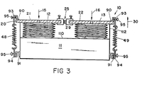
- the frame 11 is provided with a stationary end plate which defines a planar surface 110, best illustrated in Figures 2 and 3.
- the expansible chambers 12 and 13 preferably comprise a pair of pleated bellows which are generally cylindrical in shape and which include a plurality of tension rings which prevent expansion in the lateral direction.
- the bellows 12 and 13 are disposed between the stationary end plate defining the surface 110.and the movable end plates 21 and 22, respectively. When the bellows are inflated they expand in an accordion-like fashion to drive the end plates upwardly.
- the bellows are disposed in a.generally vertical orientation such that when the bellows are inflated the movable end plates are driven upwardly.
- Gravity compensating means is provided for neutralizing the effect of the weight of the movable end plates acting against the expansible chambers 12 and 13.
- the gravity compensating means is best illustrated in Figures 2 and 3.
- Arms 112 extend from the bottom of movable end plates 21 and 22.
- Brackets 113 are secured to the frame-11.
- Tension springs 114 extend between the arms 112 and the brackets 113 for providing a moment centred about the pivot axis 28 of the movable end plates which counteracts the gravitational force which would normally be applied to the bellows 12 and 13 by the weight of the movable end plates.
- One end of the springs 114 is adjustably secured to the brackets 113 by a rod 115 which is provided with a hook for engaging the spring 114 and a threaded end for insertion in an aperture in the brackets 113.
- a thumb actuated nut engages the threads on the ends of the rod 115 extending through apertures in the bracket 113 for varying the tension of the spring 114 by varying the position of the rod 115 relative to the brackets 113.
- the spring may be attached to the frame 11 by means of a bracket positionally adjustable thereto by means of screws protruding through an extended slot.
- the pleated sections of the bellows 12 and 13 are prevented from bulging in the lateral direction by a series of tension bands comrising very thin sheet metal rings which are located anugly alout each pleat Proper location of the centre section of the bellows is ensured by a guide bracket 160 which comprises a sheet metal plate having an aperture therein equal to the minor diameter of the pleats of the bellows 12 and 13.
- the bellows 12 and 13 extend through the aperture in one end of the plate 160, and the opposite end of the plate 160 is pivoted.about an axis 161 disposed in a bracket 162. that is secured to the frame 11.
- the sheet metal bracket 160 is thus permitted to pivot along with the bellows 12 and 13 when they are inflated, but it restrains the bellows from movement in a radial direction and thus prevents the bellows from.displacing when they are inflated.
- a curvilinear plate 170 is disposed proximate the free ends of the movable end plates and generally perpendicular thereto.
- the plate 170 is attached to the stationary frame 11 in any suitable fashion and is provided with printed indicia for indicating the inserted volume in the expansible chambers at various simulated compliances.
Landscapes
- Engineering & Computer Science (AREA)
- Physics & Mathematics (AREA)
- General Physics & Mathematics (AREA)
- Mathematical Physics (AREA)
- Business, Economics & Management (AREA)
- Medicinal Chemistry (AREA)
- General Health & Medical Sciences (AREA)
- Algebra (AREA)
- Computational Mathematics (AREA)
- Chemical & Material Sciences (AREA)
- Mathematical Analysis (AREA)
- Mathematical Optimization (AREA)
- Health & Medical Sciences (AREA)
- Pure & Applied Mathematics (AREA)
- Medical Informatics (AREA)
- Educational Administration (AREA)
- Educational Technology (AREA)
- Theoretical Computer Science (AREA)
- Measurement Of The Respiration, Hearing Ability, Form, And Blood Characteristics Of Living Organisms (AREA)
- Organic Low-Molecular-Weight Compounds And Preparation Thereof (AREA)
- Orthopedics, Nursing, And Contraception (AREA)
- Respiratory Apparatuses And Protective Means (AREA)
- Acyclic And Carbocyclic Compounds In Medicinal Compositions (AREA)
- Medicinal Preparation (AREA)
Priority Applications (1)
| Application Number | Priority Date | Filing Date | Title |
|---|---|---|---|
| AT82306084T ATE18614T1 (de) | 1981-11-16 | 1982-11-16 | Pneumatischer lungensimulator. |
Applications Claiming Priority (2)
| Application Number | Priority Date | Filing Date | Title |
|---|---|---|---|
| US06/321,434 US4430893A (en) | 1981-11-16 | 1981-11-16 | Pneumatic lung analog for simulation of spontaneous breathing and for testing of ventilatory devices used with spontaneously breathing patients |
| US321434 | 1981-11-16 |
Publications (3)
| Publication Number | Publication Date |
|---|---|
| EP0079795A2 true EP0079795A2 (de) | 1983-05-25 |
| EP0079795A3 EP0079795A3 (en) | 1983-07-20 |
| EP0079795B1 EP0079795B1 (de) | 1986-03-12 |
Family
ID=23250591
Family Applications (1)
| Application Number | Title | Priority Date | Filing Date |
|---|---|---|---|
| EP82306084A Expired EP0079795B1 (de) | 1981-11-16 | 1982-11-16 | Pneumatischer Lungensimulator |
Country Status (7)
| Country | Link |
|---|---|
| US (1) | US4430893A (de) |
| EP (1) | EP0079795B1 (de) |
| JP (1) | JPS5892365A (de) |
| AT (1) | ATE18614T1 (de) |
| CA (1) | CA1196391A (de) |
| DE (1) | DE3269888D1 (de) |
| ES (1) | ES8404847A1 (de) |
Cited By (6)
| Publication number | Priority date | Publication date | Assignee | Title |
|---|---|---|---|---|
| DE3427182A1 (de) * | 1984-07-24 | 1986-01-30 | Drägerwerk AG, 2400 Lübeck | Lungensimulator und betriebsverfahren hierzu |
| WO1991007737A1 (en) * | 1989-11-09 | 1991-05-30 | Richard Brault | Cpr manikin |
| US5238409A (en) * | 1992-04-06 | 1993-08-24 | Actar Airforce Inc. | Valve means for training manikin |
| EP2243129A1 (de) * | 2008-01-11 | 2010-10-27 | Laerdal Medical AS | Vorrichtung zur simulierung variabler lungendehnbarkeit |
| DE102010027436B3 (de) * | 2010-07-09 | 2011-07-21 | Schaller, Peter, Dr., 01326 | Lungensimulator |
| CN104998328A (zh) * | 2015-07-08 | 2015-10-28 | 湖南明康中锦医疗科技发展有限公司 | 模拟肺装置及模拟肺装置运行系统 |
Families Citing this family (30)
| Publication number | Priority date | Publication date | Assignee | Title |
|---|---|---|---|---|
| US4796467A (en) * | 1987-04-30 | 1989-01-10 | Biosystems Inc. | Testing device for respiratory protective devices |
| US5052934A (en) * | 1990-04-20 | 1991-10-01 | The United States Of America As Represented By The Department Of Health And Human Services | Phantom for evaluation of prosthetic valves and cardiac ultrasound procedures |
| US5473954A (en) * | 1993-03-11 | 1995-12-12 | Mh Custom Design & Mfg., L.C. | Apparatus for testing polymonary devices |
| US5385139A (en) * | 1993-05-24 | 1995-01-31 | Corn; Stephen B. | Method and apparatus for testing anethesia machine valves |
| AU7382196A (en) * | 1995-09-29 | 1997-04-17 | Ihc Health Services, Inc. | Servo lung simulator and related control method |
| US8016598B2 (en) * | 1996-05-08 | 2011-09-13 | Gaumard Scientific Company, Inc. | Interactive education system for teaching patient care |
| US7811090B2 (en) | 1996-05-08 | 2010-10-12 | Gaumard Scientific Company, Inc. | Interactive education system for teaching patient care |
| US8696362B2 (en) * | 1996-05-08 | 2014-04-15 | Gaumard Scientific Company, Inc. | Interactive education system for teaching patient care |
| US20090148822A1 (en) | 2007-12-07 | 2009-06-11 | Gaumard Scientific Company, Inc. | Interactive Education System for Teaching Patient Care |
| US7192284B2 (en) * | 2000-08-17 | 2007-03-20 | Gaumard Scientific Company, Inc. | Interactive education system for teaching patient care |
| US7976312B2 (en) * | 1996-05-08 | 2011-07-12 | Gaumard Scientific Company, Inc. | Interactive education system for teaching patient care |
| US5975748A (en) * | 1996-09-30 | 1999-11-02 | Ihc Health Services, Inc. | Servo lung simulator and related control method |
| US7976313B2 (en) * | 2000-08-17 | 2011-07-12 | Gaumard Scientific Company, Inc. | Interactive education system for teaching patient care |
| EP1687790B1 (de) * | 2003-11-25 | 2017-03-01 | Gaumard Scientific Company, Inc. | Interaktives ausbildungssystem für die pflege von patienten |
| GB0409282D0 (en) * | 2004-04-27 | 2004-06-02 | King S College London | Lung simulator |
| JP4850182B2 (ja) * | 2004-11-24 | 2012-01-11 | アイエムティー メディカル アクチエンゲゼルシャフト | 麻酔機器及び人工呼吸器を試験するための器具 |
| US7658188B2 (en) | 2005-06-06 | 2010-02-09 | Artivent Corporation | Volume-adjustable manual ventilation device |
| US7537008B2 (en) * | 2005-06-06 | 2009-05-26 | Artivent Medical Corporation | Manual ventilation or resuscitation device |
| US8235043B2 (en) | 2007-12-06 | 2012-08-07 | Artivent Corporation | Volume adjustable manual ventilation device |
| JP4224610B2 (ja) * | 2006-04-17 | 2009-02-18 | 興研株式会社 | 呼吸保護具の評価試験用模擬呼吸装置 |
| NO20080200L (no) | 2008-01-11 | 2009-07-13 | Laerdal Medical As | Mannequin med kjoleplate |
| US8585412B2 (en) | 2008-09-30 | 2013-11-19 | Covidien Lp | Configurable respiratory muscle pressure generator |
| US20110250578A1 (en) * | 2010-04-13 | 2011-10-13 | Northern Alberta Institute Of Technology | Ventilator test lung and trigger assembly |
| WO2011159172A1 (en) * | 2010-06-14 | 2011-12-22 | Airway Limited | Respiration simulator |
| US8517740B2 (en) * | 2011-02-18 | 2013-08-27 | Gaumard Scientific Company, Inc. | Lung compliance simulation system and associated methods |
| EP3782144B1 (de) | 2018-04-17 | 2023-06-07 | neosim AG | Lungensimulator für lehre und training |
| CN112204638A (zh) * | 2018-10-31 | 2021-01-08 | Micoto技术株式会社 | 医疗模拟器 |
| KR102413377B1 (ko) * | 2020-09-03 | 2022-06-24 | 건양대학교산학협력단 | 백밸브마스크 보조장치 |
| US20220108632A1 (en) * | 2020-10-05 | 2022-04-07 | Anthony David Wondka | Physiologically-correct electro-mechanical Lung Simulator |
| US11694578B2 (en) * | 2021-03-29 | 2023-07-04 | Cae Healthcare Canada Inc. | Lung simulator |
Citations (2)
| Publication number | Priority date | Publication date | Assignee | Title |
|---|---|---|---|---|
| US3785370A (en) * | 1972-09-14 | 1974-01-15 | Atomic Energy Commission | Detection of impaired pulmonary function |
| USRE29317E (en) * | 1973-01-29 | 1977-07-26 | Michigan Instruments, Inc. | Pneumatic lung analog |
Family Cites Families (9)
| Publication number | Priority date | Publication date | Assignee | Title |
|---|---|---|---|---|
| US29317A (en) * | 1860-07-24 | Coupling fob thills to axles | ||
| US2228983A (en) * | 1940-02-27 | 1941-01-14 | Martha F Mckesson | Basal metabolism diagnostic apparatus |
| FR890125A (fr) * | 1942-09-29 | 1944-01-28 | Expl Des Brevets Et Procedes C | Spiromètre |
| US2999495A (en) * | 1958-02-25 | 1961-09-12 | Lilly Co Eli | Spirometer recording device |
| US3420225A (en) * | 1964-08-21 | 1969-01-07 | Nasa | Balanced bellows spirometer |
| GB1073262A (en) * | 1964-12-11 | 1967-06-21 | Garbe Dietmar Rudolf | Volumetric measuring apparatus |
| GB1293633A (en) * | 1970-03-09 | 1972-10-18 | Medical Developments Ltd | Ventilator testing device |
| US3808706A (en) * | 1973-01-29 | 1974-05-07 | Michigan Instr Inc | Pneumatic lung analog |
| US4323078A (en) * | 1980-08-14 | 1982-04-06 | Heimlich Henry J | Collapsible respiratory exerciser |
-
1981
- 1981-11-16 US US06/321,434 patent/US4430893A/en not_active Expired - Lifetime
-
1982
- 1982-10-27 CA CA000414285A patent/CA1196391A/en not_active Expired
- 1982-11-08 JP JP57195842A patent/JPS5892365A/ja active Pending
- 1982-11-15 ES ES517371A patent/ES8404847A1/es not_active Expired
- 1982-11-16 EP EP82306084A patent/EP0079795B1/de not_active Expired
- 1982-11-16 DE DE8282306084T patent/DE3269888D1/de not_active Expired
- 1982-11-16 AT AT82306084T patent/ATE18614T1/de not_active IP Right Cessation
Patent Citations (2)
| Publication number | Priority date | Publication date | Assignee | Title |
|---|---|---|---|---|
| US3785370A (en) * | 1972-09-14 | 1974-01-15 | Atomic Energy Commission | Detection of impaired pulmonary function |
| USRE29317E (en) * | 1973-01-29 | 1977-07-26 | Michigan Instruments, Inc. | Pneumatic lung analog |
Non-Patent Citations (1)
| Title |
|---|
| MEDICAL AND BIOLOGICAL ENGINEERING, vol. 12, no. 6, November 1974, pages 873-874, Stevenage (GB); * |
Cited By (7)
| Publication number | Priority date | Publication date | Assignee | Title |
|---|---|---|---|---|
| DE3427182A1 (de) * | 1984-07-24 | 1986-01-30 | Drägerwerk AG, 2400 Lübeck | Lungensimulator und betriebsverfahren hierzu |
| WO1991007737A1 (en) * | 1989-11-09 | 1991-05-30 | Richard Brault | Cpr manikin |
| US5238409A (en) * | 1992-04-06 | 1993-08-24 | Actar Airforce Inc. | Valve means for training manikin |
| EP2243129A1 (de) * | 2008-01-11 | 2010-10-27 | Laerdal Medical AS | Vorrichtung zur simulierung variabler lungendehnbarkeit |
| EP2243129A4 (de) * | 2008-01-11 | 2014-05-21 | Laerdal Medical As | Vorrichtung zur simulierung variabler lungendehnbarkeit |
| DE102010027436B3 (de) * | 2010-07-09 | 2011-07-21 | Schaller, Peter, Dr., 01326 | Lungensimulator |
| CN104998328A (zh) * | 2015-07-08 | 2015-10-28 | 湖南明康中锦医疗科技发展有限公司 | 模拟肺装置及模拟肺装置运行系统 |
Also Published As
| Publication number | Publication date |
|---|---|
| EP0079795A3 (en) | 1983-07-20 |
| CA1196391A (en) | 1985-11-05 |
| JPS5892365A (ja) | 1983-06-01 |
| EP0079795B1 (de) | 1986-03-12 |
| ES517371A0 (es) | 1984-05-16 |
| ATE18614T1 (de) | 1986-03-15 |
| ES8404847A1 (es) | 1984-05-16 |
| US4430893A (en) | 1984-02-14 |
| DE3269888D1 (en) | 1986-04-17 |
Similar Documents
| Publication | Publication Date | Title |
|---|---|---|
| EP0079795B1 (de) | Pneumatischer Lungensimulator | |
| US3808706A (en) | Pneumatic lung analog | |
| CN101911151B (zh) | 用于模拟可变的肺顺应性的装置 | |
| EP0080155B1 (de) | Vorrichtung zur Unterstützung der Atmung | |
| EP1355689B1 (de) | Charakterisierung von maskensystemen | |
| US6066101A (en) | Airflow perturbation device and method for measuring respiratory resistance | |
| EP1295620B1 (de) | Beatmungsgerät zur Verwendung in der Untersuchung der Atmungsmechanik eines respiratorischen Systems | |
| US5403192A (en) | Simulated human lung for anesthesiology simulation | |
| EP1893266B1 (de) | Gerät, verfahren und computerprogramm zur leck-kompensierung für ein ventilator | |
| USRE29317E (en) | Pneumatic lung analog | |
| Stocks et al. | Improved accuracy of the occlusion technique for assessing total respiratory compliance in infants | |
| Bergman et al. | A comparison of some methods for measuring total respiratory resistance. | |
| JPH02159282A (ja) | 呼吸援助装置 | |
| US20220108632A1 (en) | Physiologically-correct electro-mechanical Lung Simulator | |
| O'Neil et al. | Pulmonary function testing in small laboratory mammals. | |
| US20150057559A1 (en) | Pulmonary Compliance and Air Flow Resistance | |
| Gaughan et al. | Quantification of the jet function of a jet stylet | |
| Ogura et al. | Relationship between pulmonary resistance and changes in arterial blood gas tension in dogs with nasal obstruction, and partial laryngeal obstruction | |
| Leipälä et al. | Compliance and resistance levels and unloading in proportional assist ventilation | |
| US4787627A (en) | Visual pressure monitor for respiratory breathing apparatus | |
| Polgar et al. | A method for measuring respiratory mechanics in small newborn (premature) infants. | |
| Farstad et al. | Effects of endotracheal tube size and ventilator settings on the mechanics of a test system during intermittent flow ventilation | |
| US6082357A (en) | Mechanical ventilator | |
| Hila et al. | Feedback withdrawal and changing compliance during manual hyperinflation | |
| DE102007008781A1 (de) | Vorrichtung zur Simulation einer Lunge, Prüfung von Beatmungsgeräten und Erfassung von Meßwerten |
Legal Events
| Date | Code | Title | Description |
|---|---|---|---|
| PUAI | Public reference made under article 153(3) epc to a published international application that has entered the european phase |
Free format text: ORIGINAL CODE: 0009012 |
|
| PUAL | Search report despatched |
Free format text: ORIGINAL CODE: 0009013 |
|
| AK | Designated contracting states |
Designated state(s): AT BE CH DE FR GB IT LI LU NL SE |
|
| AK | Designated contracting states |
Designated state(s): AT BE CH DE FR GB IT LI LU NL SE |
|
| 17P | Request for examination filed |
Effective date: 19840119 |
|
| GRAA | (expected) grant |
Free format text: ORIGINAL CODE: 0009210 |
|
| AK | Designated contracting states |
Kind code of ref document: B1 Designated state(s): AT BE CH DE FR GB IT LI LU NL SE |
|
| PG25 | Lapsed in a contracting state [announced via postgrant information from national office to epo] |
Ref country code: NL Effective date: 19860312 Ref country code: LI Effective date: 19860312 Ref country code: IT Free format text: LAPSE BECAUSE OF FAILURE TO SUBMIT A TRANSLATION OF THE DESCRIPTION OR TO PAY THE FEE WITHIN THE PRESCRIBED TIME-LIMIT;WARNING: LAPSES OF ITALIAN PATENTS WITH EFFECTIVE DATE BEFORE 2007 MAY HAVE OCCURRED AT ANY TIME BEFORE 2007. THE CORRECT EFFECTIVE DATE MAY BE DIFFERENT FROM THE ONE RECORDED. Effective date: 19860312 Ref country code: CH Effective date: 19860312 Ref country code: BE Effective date: 19860312 Ref country code: AT Effective date: 19860312 |
|
| REF | Corresponds to: |
Ref document number: 18614 Country of ref document: AT Date of ref document: 19860315 Kind code of ref document: T |
|
| PG25 | Lapsed in a contracting state [announced via postgrant information from national office to epo] |
Ref country code: SE Effective date: 19860331 |
|
| REF | Corresponds to: |
Ref document number: 3269888 Country of ref document: DE Date of ref document: 19860417 |
|
| ET | Fr: translation filed | ||
| REG | Reference to a national code |
Ref country code: CH Ref legal event code: PL |
|
| NLV1 | Nl: lapsed or annulled due to failure to fulfill the requirements of art. 29p and 29m of the patents act | ||
| PG25 | Lapsed in a contracting state [announced via postgrant information from national office to epo] |
Ref country code: LU Free format text: LAPSE BECAUSE OF NON-PAYMENT OF DUE FEES Effective date: 19861130 |
|
| PLBE | No opposition filed within time limit |
Free format text: ORIGINAL CODE: 0009261 |
|
| STAA | Information on the status of an ep patent application or granted ep patent |
Free format text: STATUS: NO OPPOSITION FILED WITHIN TIME LIMIT |
|
| 26N | No opposition filed | ||
| PGFP | Annual fee paid to national office [announced via postgrant information from national office to epo] |
Ref country code: GB Payment date: 19971007 Year of fee payment: 16 |
|
| PGFP | Annual fee paid to national office [announced via postgrant information from national office to epo] |
Ref country code: FR Payment date: 19971106 Year of fee payment: 16 |
|
| PGFP | Annual fee paid to national office [announced via postgrant information from national office to epo] |
Ref country code: DE Payment date: 19971127 Year of fee payment: 16 |
|
| PG25 | Lapsed in a contracting state [announced via postgrant information from national office to epo] |
Ref country code: GB Free format text: LAPSE BECAUSE OF NON-PAYMENT OF DUE FEES Effective date: 19981116 |
|
| GBPC | Gb: european patent ceased through non-payment of renewal fee |
Effective date: 19981116 |
|
| PG25 | Lapsed in a contracting state [announced via postgrant information from national office to epo] |
Ref country code: FR Free format text: LAPSE BECAUSE OF NON-PAYMENT OF DUE FEES Effective date: 19990730 |
|
| REG | Reference to a national code |
Ref country code: FR Ref legal event code: ST |
|
| PG25 | Lapsed in a contracting state [announced via postgrant information from national office to epo] |
Ref country code: DE Free format text: LAPSE BECAUSE OF NON-PAYMENT OF DUE FEES Effective date: 19990901 |