EP0079304A1 - Electrode holder for arc furnaces - Google Patents
Electrode holder for arc furnaces Download PDFInfo
- Publication number
- EP0079304A1 EP0079304A1 EP82810444A EP82810444A EP0079304A1 EP 0079304 A1 EP0079304 A1 EP 0079304A1 EP 82810444 A EP82810444 A EP 82810444A EP 82810444 A EP82810444 A EP 82810444A EP 0079304 A1 EP0079304 A1 EP 0079304A1
- Authority
- EP
- European Patent Office
- Prior art keywords
- electrode holder
- sectors
- metal shaft
- holder according
- ring
- Prior art date
- Legal status (The legal status is an assumption and is not a legal conclusion. Google has not performed a legal analysis and makes no representation as to the accuracy of the status listed.)
- Withdrawn
Links
Images


Classifications
-
- F—MECHANICAL ENGINEERING; LIGHTING; HEATING; WEAPONS; BLASTING
- F27—FURNACES; KILNS; OVENS; RETORTS
- F27B—FURNACES, KILNS, OVENS, OR RETORTS IN GENERAL; OPEN SINTERING OR LIKE APPARATUS
- F27B3/00—Hearth-type furnaces, e.g. of reverberatory type; Tank furnaces
- F27B3/08—Hearth-type furnaces, e.g. of reverberatory type; Tank furnaces heated electrically, with or without any other source of heat
-
- H—ELECTRICITY
- H05—ELECTRIC TECHNIQUES NOT OTHERWISE PROVIDED FOR
- H05B—ELECTRIC HEATING; ELECTRIC LIGHT SOURCES NOT OTHERWISE PROVIDED FOR; CIRCUIT ARRANGEMENTS FOR ELECTRIC LIGHT SOURCES, IN GENERAL
- H05B7/00—Heating by electric discharge
- H05B7/02—Details
- H05B7/12—Arrangements for cooling, sealing or protecting electrodes
-
- H—ELECTRICITY
- H05—ELECTRIC TECHNIQUES NOT OTHERWISE PROVIDED FOR
- H05B—ELECTRIC HEATING; ELECTRIC LIGHT SOURCES NOT OTHERWISE PROVIDED FOR; CIRCUIT ARRANGEMENTS FOR ELECTRIC LIGHT SOURCES, IN GENERAL
- H05B7/00—Heating by electric discharge
- H05B7/02—Details
- H05B7/10—Mountings, supports, terminals or arrangements for feeding or guiding electrodes
- H05B7/101—Mountings, supports or terminals at head of electrode, i.e. at the end remote from the arc
Definitions
- the invention relates to electrode holders for electric arc furnaces comprising a water-cooled metal shaft and a working part of consumable material, with the metal shaft being, at least partly, surrounded by moldings of high-temperature resistant material.
- Electrodes with electrode holders of the type mentioned are available in two basic designs. According to the first design the electrode consists of two axially aligned sections, i.e. the electrode holder, which constitutes the upper section, comprising a cooled metal shaft, and, at its lower tip, the active part of consumable material where the electric arc is produced. This type of electrode is generally known as combination electrode. With the second type of design, the active part of consumable material is axially movable within the electrode holder which basically comprises a cooled metal shaft. The active part of consumable material consumed at its lower tip may, therefore, be compensated for by axial movement. This type of electrode is generally known as conventional feed-through electrode. A common criterion of both designs is that the electrode holder, i.e. the liquid-cooled metal shaft, during operation projects, at least partly, into the interior of the furnace.
- Electrodes for electric arc furnaces are exposed to high thermal and mechanical stress.
- Thermal stress conditions result from the high working temperatures reached particularly in the production of electric steel.
- Mechanical stress is caused e.g. when the electrode, upon its insertion into the furnace, hits scrap material, or it may also result from movements of the molten metal or scrap material, or from vibrations caused by the electric arc.
- the electrode holder of the combination electrodes described in BE-PS 867 876 takes the form of a metal shaft which contains the cooling system and which is covered with a high-temperature resistant coating on the outside. In order to improve the adhesive capacity of this coating on the sheath area, the metal shaft has hooks holding the coating in place.
- the European patent application 0 010 305 describes a combination electrode with an electrode holder comprising a metal shaft which is electrically insulated against the current-carrying cooling system and which-can be sufficiently cooled by a high-temperature resistant material between the cooling system and the metal shaft.
- the lower section of the metal shaft, which constitutes the electrode holder, is covered with a ceramic coat that is also secured by hooks.
- the combination electrode of DE-AS 27 25 537 has a metallic, liquid-cooled upper section constituting the electrode holder, which is insulated by a high-temperature resistant material covering thermally conductive projections.
- the purpose of these projections is to prevent a direct mechanical contact with the line system if, as a result of high local stress, the high-temperature resistant material is locally damaged by rigid scrap material. At the same time these projections act as a kind of fuse, thereby preventing excessive currents from passing.
- DE-AS 27 30 884 describes a conventional feed-through electrode whose cooled metal shaft, which constitutes the .electrode holder and serves as passage through which the active part of graphite is fed, is covered with high-temperature resistant material.
- the metal shaft has projections directed radially towards the outside which fasten the high-temperature resistant material. These projections, which are distributed along the periphery and in axial direction as evenly as possible, are designed to ensure a more constant cooling and better adhesive capacity of the high-temperature resistant material.
- This solution corresponds to the protective coat designs mentioned in connection with combination electrodes. According to the most recent state of technology, the same solutions are offered for the electrode holders of combination electrodes and conventional electrodes.
- All these electrode holders have one disadvantage in common, i.e. that the protective jacket, even if it is only slightly locally damaged, has to be removed from the metal shaft of the electrode holder and a new protective jacket has to be applied,which causes lengthy interruptions and high costs.
- a further disadvantage of conventional electrode holders is the formation of slag and metal layers on the protective jacket of ceramic material, which leads to disorders in furnace operation.
- Electrode holders of this type have been employed and the protective jacket -mentioned has proved extremely useful.
- the graphite rings act as an excellent protective coat from the mechanical as well as the thermal viewpoint.
- One advantage of such a protective jacket is that, if it is partly damaged, the graphite ring in question may be exchanged, while complete removal of the jacket is only required if continuous protective coatings are used.
- a further advantage is that the formation of slag or metal layers.is avoided, for due to the destruction of the graphite surface by oxidation they keep falling off the protective jacket.
- One disadvantage is, however, that in some cases the rings show a certain tendency towards cracking which is caused by the different thermal expansion of the protective jacket and the metal shaft constituting the electrode holder, and, consequently, by the resulting tensions within the protective ring.
- the object of the present invention is to create a protective jacket for the cooled metal shaft of electrode holders of the type mentioned which fully meets all thermal, mechanical, and electrical requirements, which has a design as simple as possible, which can be easily mounted and repaired, and which guarantees a good heat transfer to the cooled metal shaft of the electrode holder in order to improve the service life of the protective jacket.
- this problem is solved by the connection of moldings to the metal shaft and/or among each other in a removable manner by means of form locking and/or resilient connection elements.
- the solution in accordance with the invention provides a protective jacket that meets all electrical, thermal, and mechanical requirements. If a resilient connection is used, the prestress of the individual moldings of the protective jacket makes them rest snugly on the metal shaft of the electrode holder, which results in a good heat transfer between protective jacket and metal shaft over the entire area. This good heat transfer is achieved without inserting any filling material between the protective jacket and the metal shaft of the electrode holder.
- the individual moldings are capable of balancing tensions caused by the different thermal expansion of the material of the protective jacket on the one hand and the material of the metal shaft of the electrode holder on the other. Thus, there is no danger of the protective jacket being damaged by this thermal expansion.
- the protective jacket is, therefore, in a position to meet all thermal requirements.
- a protective ring may be directly mounted on the metal. shaft of the electrode holder. If one or several sectors of the protective ring are damaged, the damaged sector may simply be exchanged. If the protective jacket consists of several rings each of which is made up of sectors, the ring at the lower tip of the metal shaft of the electrode-holder which is, of course, exposed to the highest strain within the furnace-and, therefore, more likely to be damaged or worn than the rings arranged further to the top, should be removed first. It should be replaced by either a new ring or a ring used in the upper section of the metal shaft that is still suitable for the lower section. In this way it is possible to replace the rings successively, to reduce assembly time, and to cut the maintenance costs for the protective jacket of the electrode holder.
- the sectors may consist of non-graphitic or partly graphitic materials containing carbon.
- the solution in accordance with the invention offers an excellent heat transfer from the protective jacket to the metal shaft of the electrode holder, it is recommended that the protective jacket be made of materials that have a low thermal conductivity.
- the materials containing carbon the so-called non-graphitic or partly graphitic materials are, therefore, especially suitable.
- ceramic materials may also be used.
- Each protective ring may have one or several spring rings, with each spring ring being formed either by one spring or by several springs connected in series.
- the springs are located in sector bores or recesses which are concentric to the ring. In this way the springs are incorporated in the sectors, which is a great advantage because they are protected against excessive thermal and mechanical stress.
- the bores or recesses are located near the inner sheath area of the sectors, which means that the springs and the cooling system of the metal shaft are as near as possible to each . other so that the temperature in the spring zone is kept as low as possible.
- the springs used may be spiral springs or leaf springs.
- the springs consist of a non-magnetic material in order to avoid the heating of the springs as a result of hysteresis losses.
- the springs should be characterized by a high heat resistance.
- the springs may be made of austenitic chrome-nickel-molybdenum steels or of material containing beryllium.
- the abutting surfaces of neighbouring sectors which lie in peripheral and/or axial direction, have at least one complementary radial graduation. Even if the abutting surfaces of neighbouring sectors do not snugly fit due to tolerances, these interlocking graduations guarantee that the sectors are well sealed, which, in turn, results in a safe protection of the cooled metal shaft of the electrode holder.
- the width of the sectors measured in peripheral direction is relatively small,with the abutting surfaces and the radial beam of the hollow cylinder forming an angle. This means that in relation to the respective radii the relatively thin sectors of a ring rest in an oblique manner on the metal shaft.
- tolerances are balanced as a result of the so-called “effect of self-adjustment", with the sectors adjusting themselves in a more vertical or a more horizontal position depending on the diameter of the metal shaft and/or the inside diameter of the sector ring.
- This sector adjustment can be observed particularly if the inner sheath areas of the sectors are smaller than the outer sheath areas resulting theoretically from the circular division.
- the result is a protective ring which, if properly mounted, has splits between the sectors. These splits become wider towards the inside.
- the sectors are arranged in such a way that wedge-like splits are formed between the sectors. As mentioned before, these splits always open up towards the inside and are closed on the outside, even if the diameter decreases.
- the sectors have a plane inner sheath area so that they can move and align themselves accordingly on the sheath area of the metal shaft.
- the outer sheath areas of the sectors may also be plane and need not have a cylindrical shape.
- the inner as well as the outer sheath area of the sectors may have suitable profiles.
- connection element may e.g. consist of highly sintered aluminium oxide.
- connection elements it will be advantageous to design the connection elements as sliding connections the sliding direction of which is parallel to the axis of the metal shaft of the electrode holder. In this way it is possible to move the moldings or individual sectors either up or down in the simple way described so that partly damaged rings or sectors can be exchanged without causing extensive assembly work or the use of an excessive number of spare or replacement rings or sectors.
- the positive sliding connection mentioned is designed as dovetail guide.
- This dovetail guide is not only mechanically solid but also enables the user to slide the sectors in a simple manner against the sheath area of the metal shaft of the electrode holder.
- the grooves of the dovetail guides are located on the inner sheath areas of the sectors, while the contact strips are mounted on the sheath area of the metal shaft. This location of grooves on the inner sheath area of the sectors is advantageous because the loss of the relatively expensive sector material, which is extremely resistant to thermal and mechanical stress, is kept to a minimum.
- the contact strips are separate components which are fastened to the sheath area of the metal shaft by riveting, bolting, welding or a similar method. This is helpful not only in saving material for the metal shaft of the electrode holder but also in mounting the contact strips on relatively thin-walled metal shafts.
- the cooled metal shaft of the electrode holder usually consists of copper, which is very expensive so that material savings are really decisive.
- the metal shaft or the pipes making up the metal shaft which are intended for the cooling agent and the current supply have to have relatively thin walls in order to obtain a cooling efficiency that is optimal for the entire unit.
- the protective jacket consists of several rings that are made up of sectors, it may be practical to place one one-piece ring between any two rings consisting of sectors. As a result, the carrying capacity of the protective jacket may be further enhanced.
- the contact strips are interrupted in axial direction of the metal shaft, with the distance between two aligned contact strip sections being not greater than the twofold axial height of a sector in this region. In this way it is possible to remove damaged or worn sectors and replace them by new ones even in the middle zone of the protective jacket without having to remove the sectors above or below. This also helps to reduce assembly time.
- the contact strip sections are grouped in rings and if the contact strips of one group and the contact strips of the axially neighbouring group are staggered in peripheral direction. This results in a sector arrangement that is staggered ring by ring, which leads to a further increase in the mechanical stability of the protective jacket.
- the axial distance between two neighbouring-groups of contact strips be somewhat greater than the axial height of the one-piece ring.
- the ring may then be turned at this place so that its grooves and the contact strips of the neighbouring groups are offset, which results in the ring being arrested in axial direction.
- the ring serves as a support for all sectors or rings consisting of sectors that are located above the ring. If, therefore, the sectors below the ring break off partly or completely, the sectors above the ring are prevented from slipping along. This means that a large part of the metal shaft of the electrode holder remains protected by undamaged sectors, even if the protective jacket is damaged considerably. In this way it is possible to keep the damage to a minimum.
- Sectors and/or one-piece rings should consist of non-graphitic or partly graphitic materials containing carbon.
- life time of protective rings will be satisfactory from the economic point of view.
- a further advantage of the carbon-containing material relates to its favourable properties as far as slag or metal splashes are concerned. If the protective rings have the proper dimensions, the oxidation of carbon will proceed as slowly as desired, especially on the hotter peripheral areas of the rings, thus preventing the troublesome accumulation of slag or metal parts that is frequently observed on ceramic coatings.
- the solution in accordance with the invention guarantees an excellent heat transfer from the protective jacket to the metal shaft. It is, therefore, recommended that materials of low thermal conductivity be used for the protective jacket. Among the materials containing carbon the so-called non-graphitic or partly graphitic materials are especially suitable for this purpose.
- ceramic materials may also be employed.
- the material of the protective jacket may vary, i.e. materials containing carbon as well as ceramic materials may be used for both sectors and one-piece rings. It is favourable to use ceramic materials where the sectors of the upper section of the metal shaft are concerned, and materials containing carbon where the lower section is concerned. Other solutions such as a mixed arrangement of rings or sectors of different materials are also possible.
- axially directed pairs of rails are affixed to the metal shaft the shape of which renders it possible to keep the axially directed rims or edges of the moldings between the rail parts projecting from the metal shaft and the metal shaft proper.
- the rails are characterized by a section adjacent to the metal shaft, a section leading away from it, and a section that is parallel to the metal shaft.
- FIG 1 is a schematic illustration of the basic structure of a combination electrode for electric arc furnaces.
- This electrode comprises an electrode holder that is formed'by a cooled metal shaft 1.
- An active part 2 of consumable material, e.g. graphite, is attached by means of a threaded nipple 3 to the lower tip of the metal shaft 1 constituting the electrode holder.
- the electrode is held by a supporting structure 4 affixed to the upper section of the metal shaft 1 of the electrode holder.
- Figure 1 is a schematic illustration only, the electrical components and cooling elements are not shown, as they may be of the conventional type.
- the only part that is important in connection with the invention is the hollow cylindrical protective jacket 5 of temperature-resistant material which surrounds that section of the metal shaft 1 which remains within the furnace, thus protecting it from excessive thermal and mechanical stress.
- the protective jacket 5 is made up of hollow cylinder sectors 10 as shown in Figure 2.
- the hollow cylinder sector has an inner 11 and an outer sheath area 12, two abutting surfaces in peripheral direction 13, and two faces in axial direction 14.
- the sector has two bores 15 which are located on one chord.
- Figures 3 and 4 clearly show how several sectors 10 form a partial ring by joining their abutting surfaces 13.
- the sectors 10 of this partial ring are connected by springs which pass through the bores 15.
- the springs shown are spiral springs 20.
- Fork-like clamping elements 21 guarantee that the spiral springs 20 are secured at the end, thus prestressing them. These elements 21 hook on counter stops located at the end of the springs 20 or on their windings, thus keeping the springs 20 in a prestressed position.
- Figure 4 illustrates on the left how the clamping elements 21 are fastened, while on the right of the illustration they are already arrested.
- Figure 5 shows how partial rings, which consist of sectors 10, are joined,thus forming a complete ring.
- the partial rings are successively joined by connecting the respective tips of the springs 20 which are kept in a prestressed position by clamping elements 21.
- clamping elements 21 Upon the removal of the clamping elements 21 the abutting surfaces of the sectors rest snugly on each other also at the places where the partial rings join.
- Such a ring which is made up of sectors 10, may either be slid on the metal shaft 1 from one-end or may be radially mounted on the metal shaft-1 in the way described by joining partial rings.
- the decisive criterion is that the rings, which consist of sectors 10, rest directly and with prestress on the sheath area of the metal shaft 1, as can be seen in Figure-1.
- Figure 6 illustrates a further possible type of connection of two springs connected in series 20 which, on the one hand, help to connect the sectors 10 among each other in the way described and which, on the other, are helpful in mounting a ring consisting of sectors 20 with a certain prestress on the metal shaft 1.
- the tips of the springs 20 are equipped with stops 22 for the respective recesses 16 at the ends of the sector bores 15, with the respective spring 20 bracing the respective sectors 10 and at the same time pressing the entire ring, which consists of sectors 10, in assembly position with prestress against the sheath area of the metal shaft 1.
- Figures 7 and 8 show a further embodiment of the sectors 10.
- the abutting surfaces 13 of the respective sectors 10 which lie in peripheral direction, have at least one complementarv graduation 17 in radial direction which engages in the way illustrated.
- the metal shaft 1 is always safely protected, even if the abutting surfaces 13 of neighbouring sectors 10 do not snugly rest on each other, thus forming a split between the individual sectors 10 that is covered by the graduations 17.
- Small splits between the individual sectors may be observed in the assembly position whenever the outside diameter of the metal shaft 1 is greater than specified and/or the inside diameter of the ring, consisting of sectors 10, of the protective jacket 5 is smaller than specified.
- Figure 9 illustrates a possible way in which the rings which consist of sectors 10 can be axially joined, if the protective jacket consists of several rings made up of sectors 10.
- the faces 14 of the individual sectors 10 have grooves 18 in peripheral direction which are intended for the joining rings 19.
- Figure 10 shows a further possibility of how the springs 20 may be fastened in the sectors 10.
- the faces 14 of the sectors 10 have recesses 15a in peripheral direction which accommodate the springs 20 in a similar way as the bores 15 do.
- the recesses 15a may also act as grooves 18 required in the embodiment according to Figure 9.
- Figure 11 is an illustration of a sector 10 whose axially directed faces and/or abutting surfaces 14 have a complementary radial graduation 17a.
- This graduation enables neighbouring sectors 10 to be positively joined in axial direction. If the faces and/or abutting surfaces 14 of neighbouring sectors 10 do not snugly fit over the entire area, the resulting split is covered by these graduations 17a.- As a result, the metal shaft 1 will always be safely protected. Furthermore, by joining the sectors 10 in a positive manner, the protective jacket 5 will be even more resistant from the mechanical point of view.
- Figure 12 and Figure 13 show further embodiments of a protective ring for an electrode in accordance with the invention.
- the width of the individual sectors 10 measured in peripheral direction is relatively small so that a large number of sectors is required for one protective ring.
- the sides 11 and 12 may be plane.
- the shape of the sectors 10 may be such that their abutting surfaces 13 and the radial beam 30a and/or 30b of the hollow cylinder form an angle or two' angles ⁇ and/or ⁇ of different sizes.
- the inner sheath areas 11 of the sectors 10 may be smaller than the outer sheath areas 12 calculated on the basis of a circular division.
- wedge-like splits 40 which become wider towards the interior, will show between the abutting surfaces 13 of the assembled protective ring that rests with prestress on the metal shaft 1.
- the tangential force component of the spring tension presses the sectors 1 0 , which join in an oblique manner and which have smaller inner sheath areas 11 . in such a manner against the metal shaft 1 that the wedge-shaped splits 40 are always closed on the outside.
- This effect' makes it possible to balance tolerances on the outside diameter of the metal shaft 1 and/or on the inside diameter of the ring made up of sectors 10. But even if the sector areas 12 are attacked by oxidation, the wedge-like splits will basically remain closed on the outside.
- the bores 15 are not located on the chord of an ideal cylinder sector but they are rather at an angle to this chord. This means for each sector that the distance between the sheath area of the metal shaft 1 and one tip of the bore 15 is greater than the distance between the sheath area of the metal shaft 1 and the other tip of the bore, with the respective tips having the same peripheral direction. In this way the tangential force component results from the spring tension which causes the "effect of self-adjustment" described earlier.
- the electrically insulating connection element 50 is used for the connection of two springs 20.
- the electrically insulating connection element 50 may e.g. be made of highly sintered aluminium oxide.
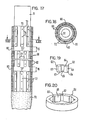
- FIG 15 is again a schematic illustration of the basic structure of a combination electrode for electric arc furnaces.
- This electrode comprises a cooled metal shaft 51 constituting the electrode holder.
- An active part 52 of consumable material, e.g. graphite, is attached to the lower tip of the metal shaft 51 by means of a threaded nipple 53.
- the electrode is held by a supporting structure 54 located in the upper section of the metal shaft 51 of the electrode holder.
- Figure 15 is a schematic illustration only, the electrical components and cooling elements of the- electrode holder are not included, as these components may have a conventional design.
- a protective jacket 55 in the form of a hollow cylinder that consists of one of the temperature-resistant materials mentioned. This jacket surrounds the metal shaft 51 of the electrode holder along the section located within the furnace, thus protecting it in the way described against detrimental thermal and mechanical stress.
- the protective jacket 55 is made up of hollow cylinder sectors. One of them is shown in the perspective illustration of Figure 19.
- the hollow cylinder sector 60 has an inner sheath area 61 and an outer sheath area 62, two abutting surfaces 63 in peripheral direction, and two faces 64 in axial direction. A number of such sectors 60 make up a ring. Several rings consisting of such sectors 60 form the protective jacket 65.
- the sectors 60 and the sheath area of the cooled metal shaft 51 are joined by means of positive connection elements. In the concrete case these positive connection elements are dovetail guides. Basically, there are two possible designs.
- the grooves 65a run in axial direction over the sheath area of the metal shaft 51, i.e. they are cut into the sheath area, while the corresponding contact strips 60a run over the inner sheath area 61 of the respective sectors 60. If this embodiment is used, the grooves 51a run continuously over the entire length of the metal shaft 51, which simplifies the manufacture of the metal shaft 51. However, in this case the sectors can be slid on the metal shaft 51 only from one end.
- the contact strips of the dovetail guides are located on the sheath area of the metal shaft 51. They are divided into contact strip sections 72 which are grouped in rings 73 taking up at least one ring, preferably,however, two or more rings consisting of sectors 60.
- the individual contact strip sections 72 are riveted or bolted 74 to the sheath area of the metal shaft 51 and are thus removable, if required.
- the axial distance 75 between two groups 73 and 73' of contact strip sections 72 is not greater.than the twofold axial height of the sectors 60 to be arranged in this region. .
- a one-piece ring 80 is shown in Figure 20.
- the inner sheath area 81 of such a ring 80 has grooves 82 which correspond or are complementary to the contact strip sections 72.
- Such a ring will, of course, be placed between two groups 73' and 73" of contact strips 72.
- the axial distance 76 between these two groups 73' and 73" of contact strip sections 72 is somewhat greater than the axial height of the ring 80.
- the ring 80 may be moved from one end of the metal shaft 51 to the zone of interruption 76 and turned in such a way that the grooves 82 and the contact strip sections 72 of group 73" and, if necessary, also those of group 73' are staggered. In this way the one-piece ring 80 will be firmly secured in axial direction either against the bottom or against both sides. If the sectors arranged below the ring 80 break under certain extreme conditions, the sectors arranged above the ring 80 are safely held by the ring 80. As a consequence, any damage of the protective jacket 55 or of the metal shaft 51 is kept to a minimum.
- the group-wise staggering of the contact strips 72 which was described earlier, serves the same purpose, since it prevents the sectors above from slipping down in case of a complete breakdown of the sectors below.
- An additional advantage of the groupwise staggering of the contact strip sections 72 is that the abutting surfaces 60 of the sectors 63 are also staggered groupwise, which further increases the solidity of the protective jacket 55.
- Figure 22 shows that the axially directed abutting surfaces and/or faces 64 of the sectors 60 of two axially neighbouring rings may have radial complementary graduations that guarantee the safe cover of these areas even if greater tolerances are involved.
- Figure 23 illustrates a cross section of the upper part of an electrode holder.
- the graphite moldings 92 may be distributed along the periphery in an even or uneven manner, they may have, but need not have, the same size as far as their length on the periphery is concerned, but they should have the same thickness.
- the rails 94 are affixed to the metal part 91 by suitable bolts. As the graphite moldings occasionally have to be exchanged, bolting is more practical than a fixed connection such as welding.
- the rails are shaped in such a way that they encompass the graphite moldings at their axial edges in such a manner that they are held against the metal part 91 without tension, for in view of the strong clamping forces of the clamping jaws 93 an excessive prestress would be highly unfavourable.
- the rails 94 are designed in such a way that one part'96 rests directly on the metal part 91, one part 97 leads away from the metal part, and one part 98 runs at a certain distance parallel to the metal part. This distance 99 is basically identical with the thickness of the graphite moldings.
Landscapes
- Engineering & Computer Science (AREA)
- Physics & Mathematics (AREA)
- Plasma & Fusion (AREA)
- Mechanical Engineering (AREA)
- General Engineering & Computer Science (AREA)
- Furnace Details (AREA)
- Discharge Heating (AREA)
- Vertical, Hearth, Or Arc Furnaces (AREA)
- Arc-Extinguishing Devices That Are Switches (AREA)
Applications Claiming Priority (4)
| Application Number | Priority Date | Filing Date | Title |
|---|---|---|---|
| DE19813144520 DE3144520A1 (de) | 1981-11-09 | 1981-11-09 | Elektrodenhalter fuer lichtbogenoefen |
| DE19813144437 DE3144437A1 (de) | 1981-11-09 | 1981-11-09 | Elektrodenhalter fuer lichtbogenoefen |
| DE3144437 | 1981-11-09 | ||
| DE3144520 | 1981-11-09 |
Publications (1)
| Publication Number | Publication Date |
|---|---|
| EP0079304A1 true EP0079304A1 (en) | 1983-05-18 |
Family
ID=25797194
Family Applications (1)
| Application Number | Title | Priority Date | Filing Date |
|---|---|---|---|
| EP82810444A Withdrawn EP0079304A1 (en) | 1981-11-09 | 1982-10-25 | Electrode holder for arc furnaces |
Country Status (11)
| Country | Link |
|---|---|
| US (1) | US4462104A (es) |
| EP (1) | EP0079304A1 (es) |
| KR (1) | KR840002095A (es) |
| BR (1) | BR8206456A (es) |
| DD (1) | DD206822A5 (es) |
| DK (1) | DK496582A (es) |
| ES (1) | ES517177A0 (es) |
| NO (1) | NO823704L (es) |
| PL (1) | PL238941A1 (es) |
| PT (1) | PT75699B (es) |
| YU (1) | YU248182A (es) |
Cited By (3)
| Publication number | Priority date | Publication date | Assignee | Title |
|---|---|---|---|---|
| FR2572874A1 (fr) * | 1984-11-02 | 1986-05-09 | Didier Werke Ag | Electrode en graphite pour un four a arc |
| EP0793400A2 (en) * | 1996-02-29 | 1997-09-03 | DANIELI & C. OFFICINE MECCANICHE S.p.A. | Adapter device for composite electrodes with an auxiliary reactance function on electric arc furnaces |
| CN104023426A (zh) * | 2014-06-07 | 2014-09-03 | 袁依凤 | 烧穿器碳棒夹持头保护装置 |
Families Citing this family (2)
| Publication number | Priority date | Publication date | Assignee | Title |
|---|---|---|---|---|
| DE3127603A1 (de) * | 1981-07-13 | 1983-01-27 | Krupp Polysius Ag, 4720 Beckum | Vorrichtung zum raeumen eines mischbettes |
| DE102009000755A1 (de) * | 2009-01-15 | 2010-07-22 | EMS Elektro Metall Schwanenmühle GmbH | Graphitelektrode mit elektrischem Anschlussstück |
Citations (5)
| Publication number | Priority date | Publication date | Assignee | Title |
|---|---|---|---|---|
| DE2725537A1 (de) * | 1977-06-06 | 1978-12-14 | Korf Stahl | Elektrode fuer lichtbogenoefen |
| DE2730884A1 (de) * | 1977-07-08 | 1979-01-11 | Korf Stahl | Fluessigkeitsgekuehlte elektrode fuer lichtbogenoefen |
| US4145564A (en) * | 1978-01-30 | 1979-03-20 | Andrew Dennie J | Non-consumable electrode with replaceable graphite tip |
| EP0010305B1 (de) * | 1978-10-18 | 1981-04-22 | Fuchs Systemtechnik GmbH | Flüssigkeitsgekühlte Halterung für eine Elektrodenspitze |
| EP0051074A1 (de) * | 1980-10-27 | 1982-05-12 | Arc Technologies Systems, Ltd. | Elektrode für Lichtbogenöfen |
Family Cites Families (3)
| Publication number | Priority date | Publication date | Assignee | Title |
|---|---|---|---|---|
| US3392227A (en) * | 1965-07-13 | 1968-07-09 | Jan Erik Ostberg | Electrode for arc furnaces |
| US3385987A (en) * | 1966-10-24 | 1968-05-28 | Westinghouse Electric Corp | Electrode for an arc furnace having a fluid cooled arcing surface and a continuouslymoving arc thereon |
| US4287381A (en) * | 1978-12-19 | 1981-09-01 | British Steel Corporation | Electric arc furnace electrodes |
-
1982
- 1982-10-19 KR KR1019820004700A patent/KR840002095A/ko unknown
- 1982-10-19 PT PT75699A patent/PT75699B/pt unknown
- 1982-10-25 EP EP82810444A patent/EP0079304A1/en not_active Withdrawn
- 1982-11-02 US US06/438,582 patent/US4462104A/en not_active Expired - Fee Related
- 1982-11-05 ES ES517177A patent/ES517177A0/es active Granted
- 1982-11-05 YU YU02481/82A patent/YU248182A/xx unknown
- 1982-11-08 BR BR8206456A patent/BR8206456A/pt unknown
- 1982-11-08 DD DD82244670A patent/DD206822A5/de unknown
- 1982-11-08 NO NO823704A patent/NO823704L/no unknown
- 1982-11-08 DK DK496582A patent/DK496582A/da not_active Application Discontinuation
- 1982-11-09 PL PL23894182A patent/PL238941A1/xx unknown
Patent Citations (5)
| Publication number | Priority date | Publication date | Assignee | Title |
|---|---|---|---|---|
| DE2725537A1 (de) * | 1977-06-06 | 1978-12-14 | Korf Stahl | Elektrode fuer lichtbogenoefen |
| DE2730884A1 (de) * | 1977-07-08 | 1979-01-11 | Korf Stahl | Fluessigkeitsgekuehlte elektrode fuer lichtbogenoefen |
| US4145564A (en) * | 1978-01-30 | 1979-03-20 | Andrew Dennie J | Non-consumable electrode with replaceable graphite tip |
| EP0010305B1 (de) * | 1978-10-18 | 1981-04-22 | Fuchs Systemtechnik GmbH | Flüssigkeitsgekühlte Halterung für eine Elektrodenspitze |
| EP0051074A1 (de) * | 1980-10-27 | 1982-05-12 | Arc Technologies Systems, Ltd. | Elektrode für Lichtbogenöfen |
Cited By (5)
| Publication number | Priority date | Publication date | Assignee | Title |
|---|---|---|---|---|
| FR2572874A1 (fr) * | 1984-11-02 | 1986-05-09 | Didier Werke Ag | Electrode en graphite pour un four a arc |
| EP0793400A2 (en) * | 1996-02-29 | 1997-09-03 | DANIELI & C. OFFICINE MECCANICHE S.p.A. | Adapter device for composite electrodes with an auxiliary reactance function on electric arc furnaces |
| EP0793400A3 (en) * | 1996-02-29 | 1998-01-07 | DANIELI & C. OFFICINE MECCANICHE S.p.A. | Adapter device for composite electrodes with an auxiliary reactance function on electric arc furnaces |
| US5940426A (en) * | 1996-02-29 | 1999-08-17 | Danieli & C. Officine Meccaniche Spa | Adapter device for composite electrodes with an auxiliary reactance function on electric arc furnaces |
| CN104023426A (zh) * | 2014-06-07 | 2014-09-03 | 袁依凤 | 烧穿器碳棒夹持头保护装置 |
Also Published As
| Publication number | Publication date |
|---|---|
| YU248182A (en) | 1985-03-20 |
| PT75699B (en) | 1984-12-03 |
| PL238941A1 (en) | 1983-05-23 |
| DD206822A5 (de) | 1984-02-08 |
| DK496582A (da) | 1983-05-10 |
| ES8405927A1 (es) | 1984-06-16 |
| PT75699A (en) | 1982-11-01 |
| KR840002095A (ko) | 1984-06-11 |
| BR8206456A (pt) | 1983-09-27 |
| ES517177A0 (es) | 1984-06-16 |
| US4462104A (en) | 1984-07-24 |
| NO823704L (no) | 1983-05-10 |
Similar Documents
| Publication | Publication Date | Title |
|---|---|---|
| CA1077997A (en) | Primary electrode arrangement for high temperature melting furnace | |
| EP0171905B1 (en) | Liquid cooled cover for electric arc furnace | |
| EP0474883B2 (en) | Dc electric furnace for melting metal | |
| EP0079304A1 (en) | Electrode holder for arc furnaces | |
| CA1198760A (en) | Electrode holder for arc furnaces | |
| JPS6036877A (ja) | 直流ア−ク炉の炉底電極装置 | |
| EP0098720A2 (en) | A furnace panel for use in an arc furnace | |
| US3804966A (en) | Furnace electrode clamp | |
| JPS60185089A (ja) | 直流アーク炉 | |
| US4610015A (en) | Electrode assembly for arc furnaces | |
| US4641320A (en) | Shroud for furnace electrode | |
| US4451926A (en) | Composite electrode for arc furnace | |
| EP0075534B1 (en) | Axially movable electrode holder for use in electric steel production | |
| US5867523A (en) | Electric furnace with conductive hearth | |
| US6075806A (en) | Coaxial electrode assembly having insulating spacers | |
| US4490824A (en) | Composite electrode for arc furnace | |
| US4416014A (en) | Composite electrode for arc furnace | |
| GB2161591A (en) | Coreless induction furnace | |
| US4447300A (en) | Electrode holder for use in fusion electrolysis | |
| GB2089629A (en) | Electrode for an arc furnace | |
| RU2550338C2 (ru) | Триангулированный сильноточный токоподвод | |
| CA1040694A (en) | Roof for arc furnace | |
| JPH0624157Y2 (ja) | 直流電気炉の炉底電極 | |
| AU710699B2 (en) | Adapter device for composite electrodes with an auxiliary reactance function on electric arc furnaces | |
| SU1336950A3 (ru) | Электрод дл получени легких металлов электролизом расплава |
Legal Events
| Date | Code | Title | Description |
|---|---|---|---|
| PUAI | Public reference made under article 153(3) epc to a published international application that has entered the european phase |
Free format text: ORIGINAL CODE: 0009012 |
|
| AK | Designated contracting states |
Designated state(s): AT BE CH DE FR GB IT LI LU NL SE |
|
| 17P | Request for examination filed |
Effective date: 19831022 |
|
| STAA | Information on the status of an ep patent application or granted ep patent |
Free format text: STATUS: THE APPLICATION IS DEEMED TO BE WITHDRAWN |
|
| 18D | Application deemed to be withdrawn |
Effective date: 19860319 |
|
| RIN1 | Information on inventor provided before grant (corrected) |
Inventor name: ZOELLNER, DIETER, DR. Inventor name: SCHIEBER, FRANZ Inventor name: LAUTERBACH-DAMMLER, INGE, DR. Inventor name: RITTMANN, FRIEDRICH |