EP0079271B1 - Branch circuit breaker with a load control by an operator module - Google Patents
Branch circuit breaker with a load control by an operator module Download PDFInfo
- Publication number
- EP0079271B1 EP0079271B1 EP19820401990 EP82401990A EP0079271B1 EP 0079271 B1 EP0079271 B1 EP 0079271B1 EP 19820401990 EP19820401990 EP 19820401990 EP 82401990 A EP82401990 A EP 82401990A EP 0079271 B1 EP0079271 B1 EP 0079271B1
- Authority
- EP
- European Patent Office
- Prior art keywords
- circuit breaker
- circuit
- relay
- operator module
- trip device
- Prior art date
- Legal status (The legal status is an assumption and is not a legal conclusion. Google has not performed a legal analysis and makes no representation as to the accuracy of the status listed.)
- Expired
Links
- 238000012544 monitoring process Methods 0.000 claims description 15
- 239000004020 conductor Substances 0.000 claims description 13
- 239000003990 capacitor Substances 0.000 claims description 12
- 238000004804 winding Methods 0.000 claims description 9
- 230000005284 excitation Effects 0.000 claims description 6
- 238000009434 installation Methods 0.000 claims description 4
- 230000005291 magnetic effect Effects 0.000 claims description 2
- 230000005405 multipole Effects 0.000 claims 1
- 239000003795 chemical substances by application Substances 0.000 description 12
- 230000003068 static effect Effects 0.000 description 7
- 239000004429 Calibre Substances 0.000 description 6
- 238000010586 diagram Methods 0.000 description 4
- 230000007935 neutral effect Effects 0.000 description 4
- 230000011664 signaling Effects 0.000 description 4
- 238000010616 electrical installation Methods 0.000 description 2
- 239000000835 fiber Substances 0.000 description 2
- 238000009825 accumulation Methods 0.000 description 1
- 230000005540 biological transmission Effects 0.000 description 1
- 230000005294 ferromagnetic effect Effects 0.000 description 1
- 238000004519 manufacturing process Methods 0.000 description 1
- 238000005259 measurement Methods 0.000 description 1
- 238000012806 monitoring device Methods 0.000 description 1
Images

Classifications
-
- H—ELECTRICITY
- H01—ELECTRIC ELEMENTS
- H01H—ELECTRIC SWITCHES; RELAYS; SELECTORS; EMERGENCY PROTECTIVE DEVICES
- H01H71/00—Details of the protective switches or relays covered by groups H01H73/00 - H01H83/00
- H01H71/10—Operating or release mechanisms
- H01H71/12—Automatic release mechanisms with or without manual release
- H01H71/123—Automatic release mechanisms with or without manual release using a solid-state trip unit
-
- H—ELECTRICITY
- H01—ELECTRIC ELEMENTS
- H01H—ELECTRIC SWITCHES; RELAYS; SELECTORS; EMERGENCY PROTECTIVE DEVICES
- H01H83/00—Protective switches, e.g. circuit-breaking switches, or protective relays operated by abnormal electrical conditions otherwise than solely by excess current
- H01H83/20—Protective switches, e.g. circuit-breaking switches, or protective relays operated by abnormal electrical conditions otherwise than solely by excess current operated by excess current as well as by some other abnormal electrical condition
-
- H—ELECTRICITY
- H01—ELECTRIC ELEMENTS
- H01H—ELECTRIC SWITCHES; RELAYS; SELECTORS; EMERGENCY PROTECTIVE DEVICES
- H01H71/00—Details of the protective switches or relays covered by groups H01H73/00 - H01H83/00
- H01H71/10—Operating or release mechanisms
- H01H71/12—Automatic release mechanisms with or without manual release
- H01H71/123—Automatic release mechanisms with or without manual release using a solid-state trip unit
- H01H2071/124—Automatic release mechanisms with or without manual release using a solid-state trip unit with a hybrid structure, the solid state trip device being combined with a thermal or a electromagnetic trip
-
- H—ELECTRICITY
- H01—ELECTRIC ELEMENTS
- H01H—ELECTRIC SWITCHES; RELAYS; SELECTORS; EMERGENCY PROTECTIVE DEVICES
- H01H83/00—Protective switches, e.g. circuit-breaking switches, or protective relays operated by abnormal electrical conditions otherwise than solely by excess current
- H01H83/20—Protective switches, e.g. circuit-breaking switches, or protective relays operated by abnormal electrical conditions otherwise than solely by excess current operated by excess current as well as by some other abnormal electrical condition
- H01H2083/203—Protective switches, e.g. circuit-breaking switches, or protective relays operated by abnormal electrical conditions otherwise than solely by excess current operated by excess current as well as by some other abnormal electrical condition with shunt trip circuits, e.g. NC contact in an undervoltage coil circuit
-
- H—ELECTRICITY
- H01—ELECTRIC ELEMENTS
- H01H—ELECTRIC SWITCHES; RELAYS; SELECTORS; EMERGENCY PROTECTIVE DEVICES
- H01H71/00—Details of the protective switches or relays covered by groups H01H73/00 - H01H83/00
- H01H71/10—Operating or release mechanisms
- H01H71/12—Automatic release mechanisms with or without manual release
- H01H71/24—Electromagnetic mechanisms
- H01H71/28—Electromagnetic mechanisms with windings acting in conjunction
-
- H—ELECTRICITY
- H01—ELECTRIC ELEMENTS
- H01H—ELECTRIC SWITCHES; RELAYS; SELECTORS; EMERGENCY PROTECTIVE DEVICES
- H01H71/00—Details of the protective switches or relays covered by groups H01H73/00 - H01H83/00
- H01H71/10—Operating or release mechanisms
- H01H71/12—Automatic release mechanisms with or without manual release
- H01H71/24—Electromagnetic mechanisms
- H01H71/32—Electromagnetic mechanisms having permanently magnetised part
-
- H—ELECTRICITY
- H02—GENERATION; CONVERSION OR DISTRIBUTION OF ELECTRIC POWER
- H02H—EMERGENCY PROTECTIVE CIRCUIT ARRANGEMENTS
- H02H3/00—Emergency protective circuit arrangements for automatic disconnection directly responsive to an undesired change from normal electric working condition with or without subsequent reconnection ; integrated protection
- H02H3/02—Details
- H02H3/04—Details with warning or supervision in addition to disconnection, e.g. for indicating that protective apparatus has functioned
Definitions
- an auxiliary power supply supplies the pilot module by connection conductors, and the circuit breaker must be equipped with a special relay for receiving the remote opening order.
- the object of the present invention is to remedy the aforementioned drawbacks and to allow the production of an improved pilot module with its own current adaptable to single-circuit or multi-gauge connection circuit breakers, with a thermothermal or static trip unit.
- the same trigger relay is thus used for the differential trigger and the emission trigger, and this relay is of the polarized type comprising two control coils.
- the pilot module has its own current and comprises, per phase, a current sensor with a toroid crossed by the phase conductor serving as primary winding and as secondary winding delivering an output signal intended to charge a capacitor. constituting an energy reservoir suitable for supplying the electronic monitoring circuit, and in the event that the subscribed power is exceeded on issuance of the remote opening order to lo, first coil of the recouis, and to the actuation of the indicator.
- the indicator of the pilot module is formed either by an electromechanical relay of the polarized type with signaling light integral with the movable pallet, or by an electronic counter intended to count and record the number of exceedances of the subscribed power.
- the circuit breaker can be adjusted at the factory to a predetermined fixed rating, for example 60A or 90A in the bipolar version, and 30A or 60A in the four-pole version.
- the circuit breaker can also be of multiple ratings, for example between 15A and 90A, the rating change being effected by an adjustment circuit cooperating with the overload release of the circuit breaker. If the subscribed power is exceeded, said overload trip device causes the local circuit breaker to trip before the remote module sends the remote opening order to the relay.
- the invention is described below as being applied to a bipolar connection circuit breaker (phase and neutral) mounted in a single-phase network, but it is obvious that the various characteristics of the invention are also applicable to circuit breakers with a different number of poles, in particular four-pole (three phases more neutral) for a three-phase network.
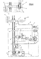
- a more neutral bipolar or unipolar connection circuit breaker 10 is connected downstream of an energy meter 12 in a single-phase alternating distribution network for supplying the low-voltage electrical installation of a customer. having subscribed to a predetermined subscription with a distribution company.
- the counter 12 is generally housed in an external electrical box accessible to the distributor agent while the connection circuit breaker 10 is arranged in the subscriber's room separate from the counter box 12 by a distance d which varies according to the distance.
- the display and the control by the agent of the caliber corresponding to the pricing of the subscription subscribed by the subscriber operate via a pilot module 14 arranged in the box nearby or inside of counter 12.
- the pilot module 14 includes a device 16 for selecting the rating, for example provided with a plurality of resistors R 11 , R, 2 , R, 3, etc. connected in voltage divider bridge with adjustment slider 18.
- the selection device 16 cooperates with an electronic monitoring circuit 20 capable of detecting exceedances of the subscribed power corresponding to a predetermined rating displayed on the device 16.
- the output of the monitoring circuit 20 is connected to an indicator device 22 with external indicator 24 signaling housed in the box.
- a link circuit 26 with pilot wires 28, 30 intended to send a remote opening order to a first coil B 1 for tripping the circuit breaker 10 if the subscribed power is exceeded.
- the single-phase connection circuit breaker 10 can be of fixed rating or multiple rating, and comprises an operating mechanism 32 of the contacts 34, 36 of the two poles associated with the phase L and neutral conductors N.
- the mechanism 32 of the circuit breaker 10 is actuated either manually by a trigger button 38 and a reset button 40, or automatically via a trigger bar (not shown) controlled by a trigger block 48 with electromagnetic trigger relay 42.
- the latter of the polarized type comprises a movable pallet 44 cooperating with the trigger bar, and a fixed ferromagnetic yoke 46 supporting a second trigger coil B 2 supplied by the trigger block 48 equipped with an overload trigger of the static type with long delay and short delay circuit or magnetothermal type, and a differential trip device with predetermined trip threshold.
- the two trigger coils 8 1 and 8 2 are mounted on the yoke 46 of the control relay 42 which is thus common to the differential trigger of the block 48, and to the emission trigger of the pilot module 14 for remote opening.
- the same tripping coil B 2 is used to actuate the realis 42 for opening the contacts 34, 36 whatever the nature of the fault current detected by the block 48.
- the pilot module 14 housed in the box of the lead counter 12 is tamper-proof, only the agent being able to adjust the size by virtue of the divider bridge with resistors R u , R 12 , R, 3 of the selection device 16.
- the rating can be adjusted to a predetermined value, for example 30, 45, 60 ... 90 Amps, corresponding respectively in a single-phase 220 Volt network to a subscribed power of 6 kW, 9 kW, 12 kW and 18 kW.
- the intensity of the current flowing in the subscriber's installation is greater than the rating selected in the device 16, the exceeding of the subscribed power is detected by.
- the monitoring circuit 20 of the pilot module 14 which simultaneously sends a first tripping signal in the connection circuit 26 for the excitation of the first coil 8 1 for tripping the relay 42 associated with the mechanism 32 of the circuit breaker 10, and a second control signal to the indicating device 22.
- the pilot module 14 thus behaves as an emission trigger for the remote opening of the contacts 34, 36 of the circuit breaker 10.
- the indicating device 22 and the indicator light 24 of the module 14 are arranged to display either directly the excess power, or with a predetermined delay corresponding to the normal tripping time of the circuit breaker 10 following the energization of the coil B 1 of the relay 42.
- the remote opening of the circuit breaker 10 by the action of the pilot module 14 is inhibited in the event of accidental or deliberate interruption of the connection circuit 26.
- the coil B i of the trip relay 42 is not energized and the overshooting of a subscribed power is then simply displayed by the indicator light 24 of the pilot unit 14 after possible recording in the indicating device 22.
- the trip unit 48 of the connection circuit breaker 10 with differential protection can include either a standard magnetothermic trip device, or an electronic trip device, and it is either single-caliber or multi-caliber.
- a standard magnetothermic trip device or an electronic trip device, and it is either single-caliber or multi-caliber.
- the appropriate setting of the overload release of the block 48 is likely in case of exceeding the subscribed power to locally cause the prior opening of the circuit breaker 10 by excitation of the second coil B 2 of the relay 42, before l transmission by the pilot module 14 of the remote trigger signal to the first coil B 1 of the relay 42. In this case, the subscriber is warned of the overshoot before the intervention of the pilot module 14 and of the indicator light 24, which remains stationary in a rest position.
- the indicating device 22 When it is impossible to install the link circuit 26 between the pilot module 14 and a multi-rating circuit breaker 10 (case of existing installations), the indicating device 22 simply signals that the power has been exceeded.
- FIG. 2 represents the simplified diagram of the electronic monitoring circuit 20 arranged in the pilot module 14.
- This circuit 20 comprises a current sensor 50, in particular a current transformer with toroid whose secondary winding provides a signal proportional to the current to monitor circulating in the primary winding formed by the phase conductor L.
- a diode bridge 52 rectifies the measurement signal from the sensor 50, and the output of the bridge 52 is connected to the voltage divider bridge with resistors R 11 , R 12 , R i3 ... forming the device for selecting the rating 16.
- the voltage taken from the cursor 18 of the selection device 16 is used to charge a capacitor C 11 which constitutes an energy reservoir used both for actuating the indicating device 22, to the excitation of the triggering coil B, of the relay 42 and to the supply of the amplifier (s) of the circuit 20.
- a Zener diode 54 for protection shunts the capacitor C 11 and is connected in parallel to the terminals d 'a resistance bias circuit 56 in series with a diode 59 connected to the negative input of an operational amplifier AO ,.
- At the terminals of the accumulation capacitor C 11 is connected on the other hand a resistor time delay circuit 60 and series capacitor 62 whose intermediate point is connected to the positive input of the operational amplifier A0 1 .
- the output voltage of amplifier A0 1 drives a thyristor 64 inserted in series in the discharge circuit of capacitor C 11 .
- the voltage across the capacitor 62 is insufficient to unblock the operational amplifier AO.
- the voltage of the capacitor 62 unblocks the amplifier A0 1 which excites the trigger of the thyristor 64.
- the conduction of the latter causes the discharge of the capacitor C 11 in the indicating device 22 and in the link circuit 26 for excitation of the coil 8 2 for remote triggering of the relay 42.
- the coil B 2 can be connected in series or in parallel with the indicating device 22.
- the pilot module 14 is at its own current and does not require no connection for an auxiliary power supply.
- FIG. 3 shows an embodiment of the indicating device 22 with signaling light 24.
- the assembly consists of an electromagnetic relay 68 polarized of the same type as that of the relay 42 for triggering the mechanism 32 of the circuit breaker 10.
- a control winding 66 mounted on the yoke of the relay 68 is supplied by the monitoring device 20 with its own current during the conduction of the thyristor 64, and causes the movable paddle 70 to detach to a separated position.
- the mechanical indicator 24 integral with the pallet 70 is projecting to induce the exceeding of the power subscribed to the agent. The latter operates the resetting of the signaling relay 68 by pressing a push button 72 requesting the pallet 70 in the position of attraction against the cylinder head.
- the indicating device 22 could be produced by an electronic counter intended to count the number of exceedances of the subscribed power.
- a recorder associated with the meter would indicate the exact date of these exceedances to the controller.
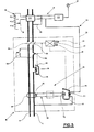
- FIG. 4 illustrates the application of a pilot module 14 according to the invention to a connection circuit breaker 10 with a trip unit 48 static.
- the same references will be used subsequently to designate identical or similar parts or components.
- the trip unit 48 of the circuit breaker 10 is for example of the type described in European patent application No. 61.364 (Art. 5413) EPO filed by the applicant.
- This block 48 includes a static overload trip device with electronic processing circuit 76 having a first long delay circuit and a second short delay circuit controlled by a current sensor 78 similar to that of the pilot module 14.
- the sensor 78 provides a proportional signal to the current flowing through the conductor L of the circuit breaker 10, and a rectifier point 80 rectifies this signal applied to an adjustment circuit 82 of the rating of the circuit breaker by the subscriber.
- This adjustment circuit 82 resembles that of the selection device 16 of the pilot module 14, and includes resistors R 21 , R 22 , R 23 ... arranged in voltage divider bridge with adjustment cursor.
- a capacitor C 21 energy accumulator is inserted between the resistance bridge and the electronic circuit 76, the output of which controls a switching circuit 84 connected to the second coil 8 2 for triggering the relay 42.
- the block 48 further comprises a trigger electromagnetic standard 86 instantaneous with fixed trip threshold, sensitive to high short-circuit currents.
- This trigger 86 is provided with a yoke 88 surrounded by one or more turns of the conductor L, and a pivoting pallet 90 mechanically cooperating with the trigger bar of the mechanism 32.
- a differential fault is detected in the block 48 by a trigger differential 92 with toroid 94 surrounding conductors L and N.
- the secondary winding 96 of torus 94 is connected to a rectifier bridge 98 connected to an electronic control circuit 100 fixing the differential tripping threshold.
- This circuit 100 cooperates with the switching circuit 84 to energize the coil 8 2 of the relay 42 after exceeding the threshold.
- the electronic circuits 76 and 100 are self-current and do not require any auxiliary power source.
- the link circuit between the pilot module 14 and the circuit breaker 10 comprises a single pilot wire 30, the other 28 pilot connection wire for the first trigger coil 8 1 being connected to the conductor L of the network playing the role of return conductor .
- the remote control of the circuit breaker 10 from the pilot module 14 is impossible, and the excess power is simply displayed on the indicator 22 of the pilot module 14.
- the opening of the circuit breaker 10 on fault can nevertheless intervene by the action of the differential trip unit 92 or the instantaneous electromagnetic trip unit 86 when a differential fault or short-circuit current occurs.
- the long delay tripping circuit associated with the sensor 78 also causes the circuit breaker 10 to open by exciting the tripping coil 8 2 of the relay 42 when the current flowing through the circuit breaker 10 exceeds 90 amperes.
- the rating displayed on the adjustment circuit 82 of the static overload release of the circuit breaker 10 corresponds to that of the selection device 16 of the pilot module 14, for example 30 amperes for a subscribed power of 6 kW.
- the time constant of the resistance 60 and capacitor 62 timing circuit associated with the operational amplifier A0 1 of the pilot module 14 is greater than the time constant of the delay circuit of the long delay tripping circuit of block 49 of the circuit breaker 10, so as to ensure, when the subscribed power is exceeded, the opening of the circuit breaker 10 due to the excitation of the coil 8 2 by the block 48, before the emission by the pilot module 14 of the remote trip signal at coil 8 1 of relay 42.
- the subscriber is thus warned of the overshoot before the warning of the pilot module 14.
- the subscriber For frequent overshoots, the subscriber must request an increase in the subscribed power, for example 9 kW adjusted by the agent on the caliber 45A of the selection circuit 16 of the pilot module 14.
- the subscriber can then display the caliber 45A on the adjustment circuit 82 of the circuit breaker 10.
- FIG. 5 represents the application of a pilot module 14 according to the invention to a single-phase connection circuit breaker 10 with magneto-thermal and differential trip unit.
- the secondary winding 96 of the differential trip device 92 with toroid 94 is connected directly and via an amplifier (in dotted lines) to the coil 8 2 of the relay 42 for tripping the circuit breaker 10.
- the magnetic circuit 46 of the relay 42 carries the coil 8 1 controlled by the pilot module 14.
- the overload trigger is formed by a bimetal strip 102 inserted in the conductor L, and cooperating directly with the trigger bar of the mechanism 32 during maximum deflection occurring after exceeding the displayed rating on the circuit breaker. The subscriber can adjust this rating by means of shunt resistors 104 for the bimetal strip 102.
- circuit breaker can be single-caliber or multi-fiber.
- the bimetallic strip 102 will be adjusted to cause, when the subscribed power is exceeded, tripping of the circuit breaker 10 by unlocking the mechanism 32, before the intervention of the module 14.
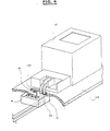
- FIG. 6 illustrates the arrangement of the pilot module 14 mounted inviolably in the table 108 of the counter 12.
- the output conductors L and N of the counter 12 pass through an opening 110 formed in the front face of the table 108, and the pilot module 14 to own current is placed under the front of the panel.
- the toroid of the current sensor 50 is disposed opposite the opening 110 and surrounds the phase conductor L.
- the installation of the pilot module 14 does not require any power connection.
- the front face is provided with a porthole or with a transparent part for viewing the indicator light 24.
Landscapes
- Emergency Protection Circuit Devices (AREA)
- Remote Monitoring And Control Of Power-Distribution Networks (AREA)
Description
L'invention est relative à un disjoncteur de branchement inséré dans un réseau multipolaire de distribution à basse tension pour l'alimentation de l'installation électrique d'un abonné dont la puissance souscrite est contrôlée par un module pilote agencé à proximité ou à l'intérieur d'un compteur d'énergie électrique, ledit module comprenant:
- un dispositif de sélection du calibre correspondant à la tarification de l'abonnement souscrit par l'abonné,
- un circuit électronique de surveillance destiné à la détection des dépoassements du calibre sélectionné au dispositif de sélection,
- un indicateur coopérant avec le circuit de surveillance pour signaler lesdits dépassements à l'agent contrôleur,
- et un déclencheur à émission actionné en cas de dépassement du calibre par le circuit de surveillance pour envoyer par l'intermédiaire d'un circuit de liaison à fils pilote un ordre d'ouverture à distance au disjoncteur.
- a device for selecting the size corresponding to the pricing of the subscription subscribed by the subscriber,
- an electronic monitoring circuit intended for detecting overflows of the caliber selected at the selection device,
- an indicator cooperating with the monitoring circuit to signal said overruns to the controlling agent,
- and a release trigger actuated in the event of overshooting of the rating by the monitoring circuit to send via a pilot wire connection circuit a remote opening order to the circuit breaker.
Selon un dispositif connu du genre mentionné, une alimentation auxiliaire alimente le module pilote par des conducteurs de raccordement, et le disjoncteur doit être équipé d'un relais spécial pour la réception de l'ordre d'ouverture à distance.According to a known device of the kind mentioned, an auxiliary power supply supplies the pilot module by connection conductors, and the circuit breaker must be equipped with a special relay for receiving the remote opening order.
La présente invention a pour but de remédier aux inconvénients précités et de permettre la réalisation d'un module pilote perfectionné à propre courant adaptable à des disjoncteurs de branchement monocalibres ou multi-calibres, à bloc déclencheur magnétothermique ou statique.The object of the present invention is to remedy the aforementioned drawbacks and to allow the production of an improved pilot module with its own current adaptable to single-circuit or multi-gauge connection circuit breakers, with a thermothermal or static trip unit.
Ce but est réalisée par la caractéristique de la revendication 1.This object is achieved by the characteristic of
On utilise ainsi le même relais de déclenchement pour le déclencheur différenttiel et le déclencheur à émission, et ce relais est du type polarisé comprenant deux bobines de commande.The same trigger relay is thus used for the differential trigger and the emission trigger, and this relay is of the polarized type comprising two control coils.
Selon une caractéristique de l'invention, le module pilote est à propre courant et comporte par phase un capteur de courant à tore traversé par le conducteur de phase servant d'enroulement primaire et à enroulement secondaire délivrant un signal de sortie destine à charger un condensateur constituant un réservoir d'énergie adapté à l'alimentation du circuit électronique de surveillance, et en cas de dépassement de la puissance souscrite à l'émission de l'ordre d'ouverture à distance vers lo, première bobine du recouis, et à l'actionnement de l'indicateur.According to a characteristic of the invention, the pilot module has its own current and comprises, per phase, a current sensor with a toroid crossed by the phase conductor serving as primary winding and as secondary winding delivering an output signal intended to charge a capacitor. constituting an energy reservoir suitable for supplying the electronic monitoring circuit, and in the event that the subscribed power is exceeded on issuance of the remote opening order to lo, first coil of the recouis, and to the actuation of the indicator.
L'indicateur du module pilote est formé soit par un relais électromécanique du type polarisé à voyant de signalisation solidaire de la palette mobile, soit par un compteur électronique destiné à compter et enregistrer le nombre de dépassements de la puissance souscrite.The indicator of the pilot module is formed either by an electromechanical relay of the polarized type with signaling light integral with the movable pallet, or by an electronic counter intended to count and record the number of exceedances of the subscribed power.
Le disjoncteur peut être ajusté en usine à un calibre fixe prédéterminé, par exemple 60A ou 90A en version bipolaire, et 30A ou 60A en version tétrapolaire.The circuit breaker can be adjusted at the factory to a predetermined fixed rating, for example 60A or 90A in the bipolar version, and 30A or 60A in the four-pole version.
Le disjoncteur peut également être à calibres multiples, par exemple entre 15A et 90A, le changement de calibres étant opéré par un circuit d'ajustage coopérant avec le déclencheur de surcharge du disjoncteur. En cas de dépassement de la puissance souscrite, ledit déclencheur de surcharge provoque le déclenchement local du disjoncteur avant l'émission par le module pilote de l'ordre d'ouverture à distance vers le relais.The circuit breaker can also be of multiple ratings, for example between 15A and 90A, the rating change being effected by an adjustment circuit cooperating with the overload release of the circuit breaker. If the subscribed power is exceeded, said overload trip device causes the local circuit breaker to trip before the remote module sends the remote opening order to the relay.
L'ouverture à distance du disjoncteur par le module pilote est inhibée en cas d'absence ou de coupure du circuit de liaison à fils pilote. Le dépassement de la puissance souscrite est alors signalé à l'agent par le voyant du bloc pilote.Remote opening of the circuit breaker by the pilot module is inhibited in the event of the absence or interruption of the pilot wire connection circuit. The oversubscribed power is then signaled to the agent by the pilot unit indicator light.
D'autres avantages et caractéristiques de l'invention resortiront plus clairement de la description qui va suivre de différents modes de réalisation donnés à titre d'exemples non limitatifs et représentés aux dessins annexés, dans lesquels:
- la figure 1 montre le schéma général électrique d'un disjoncteur de branchement monophasé télécommandé par le module pilote de contrôle de la puissance souscrite par l'abonné;
- la figure 2 illustre le schéma du module pilote;
- la figure 3 représente un mode de réalisation de l'indicateur du module pilote;
- la figure 4 montre le schéma du module pilote associé à un disjoncteur différentiel à déclencheur de surcharge statique;
- la figure 5 représente le module pilote associé à un disjoncteur différentiel à déclencheur de surcharge magnétothermique;
- la figure 6 est une vue schématique en perspective du montage du module pilote dans le tableau du compteur d'énergie.
- FIG. 1 shows the general electrical diagram of a single-phase connection circuit breaker remotely controlled by the pilot module for controlling the power subscribed by the subscriber;
- FIG. 2 illustrates the diagram of the pilot module;
- FIG. 3 represents an embodiment of the indicator of the pilot module;
- FIG. 4 shows the diagram of the pilot module associated with a differential circuit breaker with static overload release;
- FIG. 5 represents the pilot module associated with a differential circuit breaker with magnetothermal overload release;
- Figure 6 is a schematic perspective view of the mounting of the pilot module in the table of the energy meter.
A titre d'exemple, l'invention est décrite par la suite comme étant appliquée à un disjoncteur de branchement bipolaire (phase et neutre) monté dans un réseau monophasé, mais il est évident que les diverses caractéristiques de l'invention sont également applicables aux disjoncteurs ayant un nombre de pôles différents, notamment tétrapolaire (trois phases plus neutre) pour un réseau triphasé.By way of example, the invention is described below as being applied to a bipolar connection circuit breaker (phase and neutral) mounted in a single-phase network, but it is obvious that the various characteristics of the invention are also applicable to circuit breakers with a different number of poles, in particular four-pole (three phases more neutral) for a three-phase network.
Sur la figure 1, un disjoncteur de branchement 10 bipolaire ou unipolaire plus neutre est connecté en aval d'un compteur 12 d'énergie dans un réseau alternatif monophasé de distribution pour l'alimentation de l'instalation électrique à basse tension d'un client ayant souscrit un abonnement prédéterminé auprès d'une compagnie de distribution. Le compteur 12 est généralement logé dans un coffret électrique extérieur accessible à l'agent distributeur tandis que le disjoncteur 10 de branchement est disposé dans le local de l'abonné séparé du coffret du compteur 12 par une distance d variable selon l'éloignement. L'affichage et le contrôle par l'agent du calibre correspondant à la tarification de l'abonnement souscrit par l'abonné, s'opèrent par l'intermédiaire d'un module pilote 14 agencé dans le coffret à proximité ou à l'intérieur du compteur 12.In FIG. 1, a more neutral bipolar or unipolar
Le module pilote 14 comporte un dispositif de sélection 16 du calibre, doté par exemple d'une plurlité de résistances R11, R,2, R,3 ... connectées en pont diviseur de tension à curseur 18 de réglage. Le dispositif de sélection 16 coopère avec un circuit électronique de surveillance 20 susceptible de détecter les dépassements de la puissance souscrite correspondant à un calibre prédéterminé affiché au dispositif 16. La sortie du circuit de surveillance 20 est reliée à un dispositif indicateur 22 à voyant extérieur 24 de signalisation logé dans le coffret. Entre le circuit de surveillance 20 du module pilote 14 et le disjoncteur de branchement 10 est connecté un circuit de liaison 26 à fils pilote 28, 30 destiné à envoyer un odre d'ouverture à distance à une première bobine B1 de déclenchement du disjoncteur 10 en cas de dépassement de la puissance souscrite.The
Le disjoncteur de branchement 10 monophasé peut être à calibre fixe ou à calibre multiple, et comporte un mécanisme de manoeuvre 32 des contacts 34, 36 des deux pôles associés aux conducteurs de phase L et de neutre N. Le mécanisme 32 du disjoncteur 10 est actionné soit manuellement par un bouton de déclenchement 38 et un bouton de réarmement 40, soit automatiquement par l'intermédiaire d'une barre de déclenchement (non représente) pilotée par un bloc déclencheur 48 à relais électromagnétique de déclenchement 42. Ce dernier du type polarisé comprend une palette 44 mobile coopérant avec la barre de déclenchement, et une culasse 46 ferromagnétique fixe supportant une deuxième bobine B2 de déclenchement alimentée par le bloc déclencheur 48 équipé d'un déclencheur de surcharge du type statique à circuit long retard et court retard ou du type magnétothermique, et d'un déclencheur différentiel à seuil de déclenchement prédéterminé. Les deux bobines 81 et 82 de déclenchement sont montées sur la culasse 46 du relais 42 de commande qui est ainsi commun au déclencheur différentiel du bloc 48, et au déclencheur à émission du module pilote 14 d'ouverture à distance. Dans le cas d'un disjoncteur 10 de branchement à déclenceur de surcharge statique, la même bobine B2 de déclenchement sert à actionner le realis 42 pour l'ouverture des contacts 34, 36 quelle que soit la nature du courant de défaut détecté par le bloc 48.The single-phase
Le fonctionnement du disjoncteur 10 et du module pilote 14 à relais 42 de déclenchement commun selon l'invention est le suivant:The operation of the
Le module pilote 14 logé dans le coffret du compteur 12 des plombé est inviolable, seul l'agent pouvant adjuster le calibre grâce au pont diviseur à résistances Ru, R12, R,3 du dispositif de sélection 16. Selon la position du curseur 18, le calibre peut être réaglé à une valeur prédéterminée, par exemple 30, 45, 60 ... 90 Ampères, correspondant respectivement dans un réseau monophasé 220 Volts à une puissance souscrite de 6 kW, 9 kW, 12 kW et 18 kW. Lorsque l'intensité du courant circulant dans l'installation de l'abonné est supérieur au calibre sélectionné dans le dispositif 16, le dépassement de la puissance souscrite est détecté par. le circuit de surveillance 20 du module pilote 14, qui envoie simultanément un premier signal de déclenchement dans le circuit de liaison 26 pour l'excitation de la première bobine 81 de déclenchement du relais 42 associé au mécanisme 32 du disjoncteur 10, et un deuxième signal de contrôle vers le dispositif indicateur 22. Le module pilote 14 se comporte ainsi en déclencheur à émission pour l'ouverture à distance des contacts 34, 36 du disjoncteur 10. Le dispositif indicateur 22 et le voyant de signalisation 24 du module 14 sont agencés pour afficher soit directement le dépassement de la puissance, soit avec un retard prédéterminé correspondant au temps normal de déclenchement du disjoncteur 10 suite à l'excitation de la bobine B1 du relais 42.The
L'ouverture à distance du disjoncteur 10 par l'action du module pilote 14 est inhibée en cas de coupure accidentelle ou volontaire du circuit de liaison 26. La bobine Bi du relais de déclenchement 42 n'est pas excitée et le dépassement de a puissance souscrite est alors simplement visualisé par le voyant de signalisation 24 du bloc pilote 14 après enregistrement éventuel dans le dispositif indicateur 22.The remote opening of the
Le bloc déclencheur 48 du disjoncteur de branchement 10 à protection différentielle peut comporter indifféremment un déclencheur standard magnétothermique, ou un déclencheur électronique, et il est soit monocalibre, soit multi- calibres. On verra par la suite que le réglage approprié du déclencheur de surcharge du bloc 48 est susceptible en cas de dépassement de la puissance souscrite de provoquer localement l'ouverture préalable du disjoncteur 10 par excitation de la deuxième bobine B2 du relais 42, avant l'émission par le module pilote 14 du signal de déclenchement à distance à la première bobine B1 du relais 42. Dans ce cas, l'abonné est prévenu du dépassement avant l'intervention du module pilote 14 et du voyant de signalisation 24, qui reste immobile dans une position de repos.The
Lorsque la pose du circuit de liaison 26 entre le module pilote 14 et un disjoncteur 10 multi- calibres est impossible (cas des installations existantes), le dispositif indicateur 22 signale simplement le dépassement de la puissance.When it is impossible to install the
La figure 2 représente le schéma simplifié du circuit électronique de surveillance 20 agencé dans le module pilote 14. Ce circuit 20 comporte un capteur de courant 50, notamment un transformateur d'intensité à tore dont l'enroulement secondaire fournit un signal proportionnel au courant à surveiller circulant dans l'enroulement primaire formé par le conducteur L de phase. Un pont à diodes 52 redresse le signal de mesure du capteur 50, et la sortie du pont 52 est reliée au pont diviseur de tension à résistances R11, R12, Ri3... formant le dispositif de sélection 16 du calibre. La tension prélevée au curseur 18 du dispositif de sélection 16 sert à charger un condensateur C11 qui constitue un réservoir d'énergi servant à la fois à l'actionnement du dispositif indicateur 22, à l'excitation de la bobine de déclenchement B, du relais 42 et à l'alimentation du ou des amplificateurs du circuit 20. Une diode Zener 54 de protection shunte le condensateur C11 et est branchée en parallèle aux bornes d'un circuit de polarisation à résistance 56 en série avec une diode 59 connectée à l'entrée négative d'un amplificateur opérationnel AO,. Aux bornes du condensateur d'accumulation C11 est connecté d'autre part un circuit RC de temporisation à résistance 60 et condensateur 62 série dont le point intermédiaire est relié à l'entrée positive de l'amplificateur opérationnel A01. La tension de sortie de l'amplificateur A01 pilote un thyristor 64 inséré en série dans le circuit de décharge du condensateur C11. En fonctionnement normal du disjoncteur 10 traversé un courant dont l'intensité est inférieure au calibre sélectionné par le dispositif 16 du module pilote 14, la tension aux bornes du condensateur 62 est insuffisante pour débloquer l'amplificateur opérationnel AO,.FIG. 2 represents the simplified diagram of the
Lors du dépassement de la puissance souscrite, la tension du condensateur 62 assure le déblocage de l'amplificateur A01 qui excite la gâchette du thyristor 64. La conduction de ce dernier provoque la décharge du condensateur C11 dans le dispositif indicateur 22 et dans le circuit de liaison 26 pour l'excitation de la bobine 82 de déclenchement à distance du relais 42. La bobine B2 peut être connectée en série ou en parallèle avec le dispositif indicateur 22. Le module pilote 14 est à propre courant et ne nécessite aucune connexion pour une alimentation auxiliaire.When the subscribed power is exceeded, the voltage of the
La figure 3 montre un mode de réalisation du dispositif indicateur 22 à voyant de signalisation 24. L'ensemble est constitué par un relais électromagnétique 68 polarisé du même type que celui du relais 42 de déclenchement du mécanisme 32 du disjoncteur 10. Un enroulement de commande 66 monté sur la culasse du relais 68 est alimenté par le dispositif de surveillance 20 à propre courant lors de la conduction du thyristor 64, et provoque le décollement de la palette 70 mobile vers une position écarté. Le voyant 24 mécanique solidaire de la palette 70 se trouve en saillie pour induquer le dépassement de la puissance souscrite à l'agent. Ce dernier opère le réarmement du relais 68 de signalisation par enfoncement d'un bouton poussoir 72 solicitant la palette 70 en position d'attraction contre la culasse.FIG. 3 shows an embodiment of the indicating
Selon une autre variante (non représentée), le dispositif indicateur 22 pourrait être réalisé par un compteur électronique destiné à compter le nombre de dépassements de la puissance souscrite. Un enregistreur associé au compteur indiquerait la date exacte de ces dépassements à l'agent contrôleur.According to another variant (not shown), the indicating
La figure 4 illustre l'application d'un module pilote 14 selon l'invention à un disjoncteur de branchement 10 à bloc déclencheur 48 statique. Les mêmes repères seront utilisés par la suite pour désigner des pièces ou composants identiques ou similaires.FIG. 4 illustrates the application of a
Le bloc déclencheur 48 du disjoncteur 10 est par exemple du type décrit dans la demande de brevet européen N° 61.364 (Art. 5413) EPO déposé par la demanderesse. Ce bloc 48 comporte un déclencheur statique de surcharge à circuit électronique de traitement 76 ayant un premier circuit long rétard et en deuxième circuit court retard pilotés par un capteur de courant 78 similaire à celui 50 du module pilote 14. Le capteur 78 fournit un signal proportionnel au courant parcourant le conducteur L du disjoncteur 10, et un point redresseur 80 redresse ce signal appliqué à un circuit d'adjustage 82 du calibre du disjoncteur par l'abonné. Ce circuit d'ajustage 82 ressemble à celui du dispositif de sélection 16 du module pilote 14, et comprend des résistances R21, R22, R23 ...agencées en pont diviseur de tension à curseur de réglage. Un condensateur C21 accumulateur d'énergie est inséré entre le pont de résistances et le circuit électronique 76 dont la sortie pilote un circuit de commutation 84 relié à la deuxième bobine 82 de déclenchement du relais 42. Le bloc 48 comprend de plus un déclencheur standard électromagnétique 86 instantané à seuil de déclenchement fixe, sensible à des courants de court-circuit élevés. Ce déclencheur 86 est muni d'une culasse 88 entourée par un ou plusieurs tours du conducteur L, et d'une palette 90 pivotante coopérant mécaniquement avec la barre de déclenchement du mécanisme 32. Un défaut différentiel est détecté dans le bloc 48 par un déclencheur différentiel 92 à tore 94 entourant les conducteurs L et N. L'enroulement secondaire 96 du tore 94 est connecté à un pont redresseur 98 branché à un circuit électronique de commande 100 fixant le seuil de déclenchement différentiel. Ce circuit 100 coopère avec le circuit de commutation 84 pour exciter la bobine 82 du relais 42 après dépassement de seuil. Les circuits électroniques 76 et 100 sont à propre courant et ne nécissitent aucune source d'alimentation auxiliaire.The
Le circuit de liaison entre le module pilote 14 et le disjoncteur 10 comprend un fil pilote 30 unique, l'autre 28 fil pilote de connexion de la première bobine 81 de déclenchement étant connecté au conducteur L du réseau jouant le rôle de conducteur de retour.The link circuit between the
Le fonctionnement du disjoncteur selon la figure 4 est le suivant:
- Pour un disjoncteur 10 de branchement monocalibre, le curseur du
circuit d'ajustage 82 est fixé en usine dans une position prédéterminée, par exemple à un calibre de 90 Ampères, et l'abonné ne procède à aucun changement de calibre au niveau du disjoncteur 10. Pour une puissance souscrite de 6 kW par exemple, l'agent affiche le calibre 30A au dispositif de sélection 16 dumodule pilote 14. Lors d'un dépassement de la puissance intervenant pour tout intensité de courant supérieure à 30A,le module pilote 14 se comporte en déclencheur à émission délivrant un ordre de déclenchement à la bobine B1 du relais 42 pour l'ouverture à distance descontacts
- For a
circuit breaker 10 of single-gauge connection, the cursor of theadjustment circuit 82 is fixed in the factory in a predetermined position, for example at a rating of 90 amperes, and the subscriber does not make any change of rating at the level of thecircuit breaker 10 For a subscribed power of 6 kW for example, the agent displays the caliber 30A at theselection device 16 of thepilot module 14. When the power intervening for any current intensity greater than 30A is exceeded, thepilot module 14 behaves as an emission trigger delivering a tripping order to the coil B 1 of therelay 42 for the remote opening of thecontacts circuit breaker 10. The indicatingdevice 22 signals this overshoot to the agent.
En cas de discontinuité ou d'absence de circuit de liaison 26, la télécommande du disjoncteur 10 depuis le module pilote 14 est impossible, et le dépassement de la puissance est simplement affichée à l'indicateur 22 du module pilote 14. L'ouverture du disjoncteur 10 sur défaut peut néanmoins intervenir par l'action du déclencheur différentiel 92 ou du déclencheur électromagnétique 86 instantané lors de l'apparition d'un courant de défaut différentiel ou de court-circuit. Le circuit de déclenchement long retard associé au capteur 78 provoque également l'ouverture du disjoncteur 10 par excitation de la bobine de déclenchement 82 du relais 42 lorsqu l'intensité parcourant le disjoncteur 10 dépasse 90 Ampères.In case of discontinuity or absence of
Pour un disjoncteur de branchement 10 multi- calibres, le calibre affiché au circuit d'ajustage 82 du déclencheur statique de surcharge du disjoncteur 10 correspond à celui du dispositif de sélection 16 du module pilote 14, par exemple 30 Ampères pour une puissance souscrite de 6 kW. La constante de temps du circuit de temporisation à résistance 60 et capacité 62 associé à l'amplificateur opérationnel A01 du module pilote 14 est supérieure à la constante de temps du circuit de temporisation du circuit de déclenchement long retard du bloc 49 du disjoncteur 10, de manière à assurer lors d'un dépassement de la puissance souscrite l'ouverture du disjoncteur 10 due à l'excitation de la bobine 82 par le bloc 48, avant l'émission par le module pilote 14 du signal de déclenchement à distance à la bobine 81 du relais 42. L'abonné est ainsi prévenu du dépassement avant l'invervention du module pilote 14. Pour des dépassements fréquents, l'abonné devra demander une augmentation de la puissance souscrite, par exemple 9 kW ajustée par l'agent sur le calibre 45A du circuit de sélection 16 du module pilote 14. L'abonné pourra ensuite afficher le calibre 45A sur le circuit d'ajustage 82 du disjoncteur 10.For a multi-gauge
La figure 5 représente l'application d'un module pilote 14 selon l'invention à un disjoncteur de branchement 10 monophasé à bloc déclencheur magnétothermique et différentiel. L'enroulement secondaire 96 du déclencheur différentiel 92 à tore 94 est connecté directement et par l'intermédiaire d'un amplificateur (en pointillé) à la bobine 82 du relais 42 de déclenchement du disjoncteur 10. Le circuit magnétique 46 du relais 42 porte la bobine 81 pilotée par le module pilote 14. Le déclencheur de surcharge est formé par un bilame 102 inséré dans le conducteur L, et coopérant directement avec la barre de déclenchement du mécanisme 32 lors d'une déflexion maximum intervenant après dépassement du calibre affiché sur le disjoncteur. L'abonné peut ajuster ce calibre grâce à des résistances 104 de shuntage du bilame 102. Le fonctionnement de ce dispositif est similaire à celui de la figure 4, et le disjoncteur peut être monocalibre ou multicalibres. Dans le cas d'un disjoncteur 10 multicalibres, le bilame 102 sera réglé pour provoquer lors du dépassement de la puissance souscrite le déclenchement du disjoncteur 10 par déverrouillage du mécanisme 32, avant l'intervention du module 14.FIG. 5 represents the application of a
La figure 6 illustre l'agencement du module pilote 14 monté inviolable dans le tableau 108 du compteur 12. Les conducteurs L et N de sortie du compteur 12 traversent une ouverture 110 ménagée dans la face avant du tableau 108, et le module pilote 14 à propre courant est placé sous la face avant du tableau. Le tore du capteur de courant 50 est disposé en regard de l'ouverture 110 et entoure le conducteur L de phase. La mise en place du module pilote 14 ne nécessite aucune connexion de puissance. La face avant est dotée d'un hublot ou d'une partie transparente pour visualiser le voyant 24 de signalisation.FIG. 6 illustrates the arrangement of the
Claims (6)
Applications Claiming Priority (2)
| Application Number | Priority Date | Filing Date | Title |
|---|---|---|---|
| FR8120991A FR2516305A1 (en) | 1981-11-06 | 1981-11-06 | CONNECTION BREAKER WITH POWER CONTROL SUBSCRIBED BY A PILOT MODULE |
| FR8120991 | 1981-11-06 |
Publications (2)
| Publication Number | Publication Date |
|---|---|
| EP0079271A1 EP0079271A1 (en) | 1983-05-18 |
| EP0079271B1 true EP0079271B1 (en) | 1986-01-29 |
Family
ID=9263846
Family Applications (1)
| Application Number | Title | Priority Date | Filing Date |
|---|---|---|---|
| EP19820401990 Expired EP0079271B1 (en) | 1981-11-06 | 1982-10-27 | Branch circuit breaker with a load control by an operator module |
Country Status (5)
| Country | Link |
|---|---|
| EP (1) | EP0079271B1 (en) |
| DE (1) | DE3268879D1 (en) |
| ES (1) | ES517099A0 (en) |
| FR (1) | FR2516305A1 (en) |
| PT (1) | PT75713B (en) |
Cited By (1)
| Publication number | Priority date | Publication date | Assignee | Title |
|---|---|---|---|---|
| DE102008052949A1 (en) * | 2008-10-23 | 2010-04-29 | Siemens Aktiengesellschaft | Method of protection against overvoltage in a system connected to a power supply system, overvoltage protection device and arrangement with such |
Families Citing this family (9)
| Publication number | Priority date | Publication date | Assignee | Title |
|---|---|---|---|---|
| FR2534063A1 (en) * | 1982-09-30 | 1984-04-06 | Merlin Gerin | CONNECTION CIRCUIT BREAKER WITH ELECTRONIC TRIGGER AND TELECALIBRATION |
| US4786885A (en) * | 1987-12-16 | 1988-11-22 | General Electric Company | Molded case circuit breaker shunt trip unit |
| US6094126A (en) * | 1999-06-08 | 2000-07-25 | Sorenson; Richard W. | Thermal circuit breaker switch |
| CN1276617A (en) * | 1999-06-08 | 2000-12-13 | 理查德·W·索伦森 | Thermal loop breaker switch |
| US6175288B1 (en) * | 1999-08-27 | 2001-01-16 | General Electric Company | Supplemental trip unit for rotary circuit interrupters |
| FR2997573B1 (en) | 2012-10-26 | 2015-01-02 | Hager Electro Sas | COMMUNICATION WITHOUT WIRING DEDICATED FROM A MONITORED CIRCUIT FOR ACTION ON AN UPPER DISCONNECT |
| CN108987203B (en) * | 2018-09-21 | 2020-01-31 | 国网福建省电力有限公司 | intelligent air switch device with automatic on-off capability |
| FR3109665B1 (en) * | 2020-04-24 | 2022-03-25 | Hager Electro Sas | Circuit breaker with electronic trip control |
| CN116110753B (en) * | 2023-04-11 | 2023-07-04 | 宁波天安智能电网科技股份有限公司 | Adjustable breaker safety loop system |
Family Cites Families (4)
| Publication number | Priority date | Publication date | Assignee | Title |
|---|---|---|---|---|
| FR2283542A1 (en) * | 1974-08-28 | 1976-03-26 | Merlin Gerin | Differential current circuit breaker - has artificial differential current created by micro-switch and resistance for remote control |
| US4068283A (en) * | 1976-10-01 | 1978-01-10 | General Electric Company | Circuit breaker solid state trip unit incorporating trip indicating circuit |
| US4213165A (en) * | 1978-03-16 | 1980-07-15 | Square D Company | Circuit breaker having an electronic fault sensing and trip initiating unit |
| FR2440609A1 (en) * | 1978-11-06 | 1980-05-30 | Merlin Gerin | Auxiliary test block for differential protection circuit breaker - permits remote operation of test circuit on circuit-breaker and has fuse and protective contact shunted by resistance lamp parts |
-
1981
- 1981-11-06 FR FR8120991A patent/FR2516305A1/en active Granted
-
1982
- 1982-10-21 PT PT7571382A patent/PT75713B/en unknown
- 1982-10-27 DE DE8282401990T patent/DE3268879D1/en not_active Expired
- 1982-10-27 EP EP19820401990 patent/EP0079271B1/en not_active Expired
- 1982-11-04 ES ES517099A patent/ES517099A0/en active Granted
Cited By (2)
| Publication number | Priority date | Publication date | Assignee | Title |
|---|---|---|---|---|
| DE102008052949A1 (en) * | 2008-10-23 | 2010-04-29 | Siemens Aktiengesellschaft | Method of protection against overvoltage in a system connected to a power supply system, overvoltage protection device and arrangement with such |
| DE102008052949B4 (en) * | 2008-10-23 | 2010-10-21 | Siemens Aktiengesellschaft | Method of protection against overvoltage in a system connected to a power supply system, overvoltage protection device and arrangement with such |
Also Published As
| Publication number | Publication date |
|---|---|
| ES8308150A1 (en) | 1983-08-01 |
| FR2516305A1 (en) | 1983-05-13 |
| PT75713B (en) | 1985-01-02 |
| EP0079271A1 (en) | 1983-05-18 |
| FR2516305B1 (en) | 1983-12-23 |
| ES517099A0 (en) | 1983-08-01 |
| DE3268879D1 (en) | 1986-03-13 |
| PT75713A (en) | 1982-11-01 |
Similar Documents
| Publication | Publication Date | Title |
|---|---|---|
| EP0367690B1 (en) | Tripping circuit with test circuit and selfprotected remote control for opening | |
| FI66096B (en) | ELEKTRISK FULLSKYDDSKOPPLING | |
| JP2510508B2 (en) | Digital solid trip device for circuit breaker | |
| US4081852A (en) | Ground fault circuit breaker | |
| AU652019B2 (en) | Fault current circuit breaker | |
| JPH0334038Y2 (en) | ||
| US9783071B2 (en) | Device and method for providing a quantity of energy in said supply device for consumer | |
| EP1329733A2 (en) | Arcing fault detection system | |
| EP0079271B1 (en) | Branch circuit breaker with a load control by an operator module | |
| FR2547122A1 (en) | SELECTIVE ELECTRONIC TRIGGER ASSOCIATED WITH A LIMITING CIRCUIT BREAKER | |
| US4308511A (en) | Load management circuit breaker | |
| US4466042A (en) | Trip indicator assembly for electronic circuit breaker | |
| US6377431B1 (en) | Non-automatic power circuit breaker including trip mechanism which is disabled after closure of separable contacts | |
| US5095398A (en) | Electrical circuit breaker protection device | |
| EP2181457B1 (en) | Electrical switching apparatus, circuit interrupter and method of interrupting overcurrents of a power circuit | |
| US5633776A (en) | Circuit breaker | |
| EP0665623B1 (en) | Test device for differential circuit breaker and differential circuit breaker containing the same | |
| FR2497013A1 (en) | Automatic load shedding controller for electrical installation - uses overcurrent detectors on input supply to disconnect low priority loads if input current becomes excessive | |
| EP0079270B1 (en) | Low-voltage branch circuit breaker provided with a remotely controlled calibration switch | |
| FR2752479A1 (en) | Differential electronic circuit breaker for electrical Protection | |
| EP0105786B1 (en) | Branch circuit breaker with an electronic trip device and remotely controlled calibration | |
| EP4016777B1 (en) | Electrical device for protecting an alternating current electrical installation | |
| EP3511970B1 (en) | Electronic switch with a detector for providing information about the tripping of the switch on a bus | |
| SU1304127A1 (en) | Device for remote disconnection of circuit breaker | |
| US2905864A (en) | Circuit protective variable ratio transformer system |
Legal Events
| Date | Code | Title | Description |
|---|---|---|---|
| PUAI | Public reference made under article 153(3) epc to a published international application that has entered the european phase |
Free format text: ORIGINAL CODE: 0009012 |
|
| AK | Designated contracting states |
Designated state(s): BE CH DE GB IT LI NL SE |
|
| 17P | Request for examination filed |
Effective date: 19830929 |
|
| ITF | It: translation for a ep patent filed | ||
| GRAA | (expected) grant |
Free format text: ORIGINAL CODE: 0009210 |
|
| AK | Designated contracting states |
Designated state(s): BE CH DE GB IT LI NL SE |
|
| REF | Corresponds to: |
Ref document number: 3268879 Country of ref document: DE Date of ref document: 19860313 |
|
| PLBE | No opposition filed within time limit |
Free format text: ORIGINAL CODE: 0009261 |
|
| STAA | Information on the status of an ep patent application or granted ep patent |
Free format text: STATUS: NO OPPOSITION FILED WITHIN TIME LIMIT |
|
| 26N | No opposition filed | ||
| PGFP | Annual fee paid to national office [announced via postgrant information from national office to epo] |
Ref country code: SE Payment date: 19910927 Year of fee payment: 10 |
|
| PGFP | Annual fee paid to national office [announced via postgrant information from national office to epo] |
Ref country code: CH Payment date: 19911025 Year of fee payment: 10 |
|
| ITTA | It: last paid annual fee | ||
| PGFP | Annual fee paid to national office [announced via postgrant information from national office to epo] |
Ref country code: NL Payment date: 19911031 Year of fee payment: 10 |
|
| PG25 | Lapsed in a contracting state [announced via postgrant information from national office to epo] |
Ref country code: SE Effective date: 19921028 |
|
| PG25 | Lapsed in a contracting state [announced via postgrant information from national office to epo] |
Ref country code: LI Effective date: 19921031 Ref country code: CH Effective date: 19921031 |
|
| PG25 | Lapsed in a contracting state [announced via postgrant information from national office to epo] |
Ref country code: NL Effective date: 19930501 |
|
| NLV4 | Nl: lapsed or anulled due to non-payment of the annual fee | ||
| REG | Reference to a national code |
Ref country code: CH Ref legal event code: PL |
|
| EUG | Se: european patent has lapsed |
Ref document number: 82401990.5 Effective date: 19930510 |
|
| PGFP | Annual fee paid to national office [announced via postgrant information from national office to epo] |
Ref country code: GB Payment date: 19961018 Year of fee payment: 15 |
|
| PGFP | Annual fee paid to national office [announced via postgrant information from national office to epo] |
Ref country code: BE Payment date: 19961212 Year of fee payment: 15 |
|
| PGFP | Annual fee paid to national office [announced via postgrant information from national office to epo] |
Ref country code: DE Payment date: 19971013 Year of fee payment: 16 |
|
| PG25 | Lapsed in a contracting state [announced via postgrant information from national office to epo] |
Ref country code: GB Free format text: LAPSE BECAUSE OF NON-PAYMENT OF DUE FEES Effective date: 19971027 |
|
| PG25 | Lapsed in a contracting state [announced via postgrant information from national office to epo] |
Ref country code: BE Free format text: LAPSE BECAUSE OF NON-PAYMENT OF DUE FEES Effective date: 19971031 |
|
| BERE | Be: lapsed |
Owner name: MERLIN GERIN Effective date: 19971031 |
|
| GBPC | Gb: european patent ceased through non-payment of renewal fee |
Effective date: 19971027 |
|
| PG25 | Lapsed in a contracting state [announced via postgrant information from national office to epo] |
Ref country code: DE Free format text: LAPSE BECAUSE OF NON-PAYMENT OF DUE FEES Effective date: 19990803 |