EP0079267A1 - Netzunabhängige Pfostenleuchte - Google Patents
Netzunabhängige Pfostenleuchte Download PDFInfo
- Publication number
- EP0079267A1 EP0079267A1 EP82401981A EP82401981A EP0079267A1 EP 0079267 A1 EP0079267 A1 EP 0079267A1 EP 82401981 A EP82401981 A EP 82401981A EP 82401981 A EP82401981 A EP 82401981A EP 0079267 A1 EP0079267 A1 EP 0079267A1
- Authority
- EP
- European Patent Office
- Prior art keywords
- autonomous
- light
- order
- control
- terminal
- Prior art date
- Legal status (The legal status is an assumption and is not a legal conclusion. Google has not performed a legal analysis and makes no representation as to the accuracy of the status listed.)
- Withdrawn
Links
Images

Classifications
-
- F—MECHANICAL ENGINEERING; LIGHTING; HEATING; WEAPONS; BLASTING
- F21—LIGHTING
- F21V—FUNCTIONAL FEATURES OR DETAILS OF LIGHTING DEVICES OR SYSTEMS THEREOF; STRUCTURAL COMBINATIONS OF LIGHTING DEVICES WITH OTHER ARTICLES, NOT OTHERWISE PROVIDED FOR
- F21V7/00—Reflectors for light sources
- F21V7/0025—Combination of two or more reflectors for a single light source
-
- E—FIXED CONSTRUCTIONS
- E01—CONSTRUCTION OF ROADS, RAILWAYS, OR BRIDGES
- E01F—ADDITIONAL WORK, SUCH AS EQUIPPING ROADS OR THE CONSTRUCTION OF PLATFORMS, HELICOPTER LANDING STAGES, SIGNS, SNOW FENCES, OR THE LIKE
- E01F9/00—Arrangement of road signs or traffic signals; Arrangements for enforcing caution
- E01F9/60—Upright bodies, e.g. marker posts or bollards; Supports for road signs
- E01F9/604—Upright bodies, e.g. marker posts or bollards; Supports for road signs specially adapted for particular signalling purposes, e.g. for indicating curves, road works or pedestrian crossings
- E01F9/615—Upright bodies, e.g. marker posts or bollards; Supports for road signs specially adapted for particular signalling purposes, e.g. for indicating curves, road works or pedestrian crossings illuminated
- E01F9/617—Illuminated or wired-up posts, bollards, pillars or like upstanding bodies or structures for traffic guidance, warning or control
-
- F—MECHANICAL ENGINEERING; LIGHTING; HEATING; WEAPONS; BLASTING
- F21—LIGHTING
- F21S—NON-PORTABLE LIGHTING DEVICES; SYSTEMS THEREOF; VEHICLE LIGHTING DEVICES SPECIALLY ADAPTED FOR VEHICLE EXTERIORS
- F21S8/00—Lighting devices intended for fixed installation
- F21S8/08—Lighting devices intended for fixed installation with a standard
- F21S8/081—Lighting devices intended for fixed installation with a standard of low-built type, e.g. landscape light
- F21S8/083—Lighting devices intended for fixed installation with a standard of low-built type, e.g. landscape light of bollard type, i.e. with lighting fixture integrated into the standard or mounted on top of it and having substantially the same diameter
-
- F—MECHANICAL ENGINEERING; LIGHTING; HEATING; WEAPONS; BLASTING
- F21—LIGHTING
- F21S—NON-PORTABLE LIGHTING DEVICES; SYSTEMS THEREOF; VEHICLE LIGHTING DEVICES SPECIALLY ADAPTED FOR VEHICLE EXTERIORS
- F21S9/00—Lighting devices with a built-in power supply; Systems employing lighting devices with a built-in power supply
- F21S9/02—Lighting devices with a built-in power supply; Systems employing lighting devices with a built-in power supply the power supply being a battery or accumulator
- F21S9/03—Lighting devices with a built-in power supply; Systems employing lighting devices with a built-in power supply the power supply being a battery or accumulator rechargeable by exposure to light
- F21S9/037—Lighting devices with a built-in power supply; Systems employing lighting devices with a built-in power supply the power supply being a battery or accumulator rechargeable by exposure to light the solar unit and the lighting unit being located within or on the same housing
-
- F—MECHANICAL ENGINEERING; LIGHTING; HEATING; WEAPONS; BLASTING
- F21—LIGHTING
- F21V—FUNCTIONAL FEATURES OR DETAILS OF LIGHTING DEVICES OR SYSTEMS THEREOF; STRUCTURAL COMBINATIONS OF LIGHTING DEVICES WITH OTHER ARTICLES, NOT OTHERWISE PROVIDED FOR
- F21V7/00—Reflectors for light sources
- F21V7/005—Reflectors for light sources with an elongated shape to cooperate with linear light sources
-
- F—MECHANICAL ENGINEERING; LIGHTING; HEATING; WEAPONS; BLASTING
- F21—LIGHTING
- F21W—INDEXING SCHEME ASSOCIATED WITH SUBCLASSES F21K, F21L, F21S and F21V, RELATING TO USES OR APPLICATIONS OF LIGHTING DEVICES OR SYSTEMS
- F21W2111/00—Use or application of lighting devices or systems for signalling, marking or indicating, not provided for in codes F21W2102/00 – F21W2107/00
- F21W2111/02—Use or application of lighting devices or systems for signalling, marking or indicating, not provided for in codes F21W2102/00 – F21W2107/00 for roads, paths or the like
-
- F—MECHANICAL ENGINEERING; LIGHTING; HEATING; WEAPONS; BLASTING
- F21—LIGHTING
- F21Y—INDEXING SCHEME ASSOCIATED WITH SUBCLASSES F21K, F21L, F21S and F21V, RELATING TO THE FORM OR THE KIND OF THE LIGHT SOURCES OR OF THE COLOUR OF THE LIGHT EMITTED
- F21Y2103/00—Elongate light sources, e.g. fluorescent tubes
Definitions
- the invention relates to an autonomous outdoor lighting bollard, in public or private places.
- a set of photovoltaic cells provides a power of around 30W, in good conditions of lighting by the sun. These conditions can vary considerably during the day, and the energy capable of being stored by accumulators allows a lighting autonomy of approximately one night, provided that the power of the source of light is limited to ten watts. light.
- the present invention relates to an autonomous lighting bollard, the energy source of which is a device which converts solar energy directly into electrical energy, making it possible to illuminate with normal intensity places such as, for example, parts of garden or path.
- such a lighting terminal although using a direct converter of solar energy into electricity, has sufficient autonomy while retaining the quality of ambient lighting, by concentrating energy light available to preferred areas.
- an autonomous lighting terminal comprising a device for converting solar energy into electrical energy, an accumulator device; is characterized in that these devices cooperate with first electronic control means, for supplying an optical unit constituted by a light source and at least one reflecting means, concentrating the light in the form of sheets in different delimited areas.
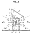
- Figure 1 shows an autonomous lighting terminal 1 according to the invention.
- a device 2 for converting solar energy into electrical energy comprising in the nonlimiting example of the description, a set 3 of photovoltaic cells whose receiving surface 4 is likely to be oriented towards the Sun.
- the assembly 3 is mounted in leaktight manner on a cradle 5, the bottom plate 6 of which is curved according to an arc of circle, center 7.
- the cradle 5 rests on a column 8 of circular section, the top 9 of which matches the shape of the bottom 6; the cradle 5 is fixed to the column 8 by conventional means not shown; this attachment can be final, or preferably carried out by means of articulation means 120, shown in dotted lines.
- the device 2 is capable of a rotational movement, around the center 7 according to an arrow 10, which allows its orientation.
- a sensor 11 consisting of a light-sensitive cell, intended to sense the ambient light level, is embedded in column 8.
- the latter comprises around its entire periphery, a wall 12 transparent to light; this light, concentrated in at least two layers A ', B' of different directions A, B, is produced by an optical unit 18 to which this wall 12 serves as protection against bad weather.
- the optical unit 18, shown diagrammatically, constitutes a first nonlimiting version, visible through an opening made in the drawing of the wall 12.
- This optical unit notably includes a light source 20 which, in the example described is a pseudo-point source 14, located in a reflecting means R in which this source is maintained by conventional means not shown.
- a light source 20 which, in the example described is a pseudo-point source 14, located in a reflecting means R in which this source is maintained by conventional means not shown.
- the reflecting means R consists of the assembly of two reflectors 22, 23, of frustoconical shape for example or as shown in FIG. 1, pseudo parabolic, joined by their top 24, 25, and centered around a longitudinal axis yy; the pseudo-point source 14 being centered on this axis yy at the intersection thereof with an axis ZZ, at the level of which the junction of the reflectors 22, 23 is effected.
- the light flux emitted by the pseudo-point source 14 is shared between the reflectors 22, 23, and concentrated by these in light layers A ', B', projected in directions represented by the arrows A and B.
- This arrangement is remarkable in that it allows, thanks to the reflecting means R, comprising two reflectors 22, 23 communicating through their apex 24, 25, to concentrate the light flow in at least two layers A ', B' of directions A , B by lighting only previously determined areas.
- Such a reflecting means may also include reflectors 22, 23 oriented differently, making it possible to concentrate the light in layers A ', B', of direction A, Al, A2 ... AN for one and B, Bl, B2 , B ... N for the other, so as to favor for example the lighting of the ground 26 on which the autonomous terminal 1 is placed.
- a lower level 13 of column 8 contains first means 100 and possibly second electronic control means 150, a device 15 of accumulators, shown in dotted lines and described in a later phase of the description.
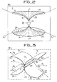
- FIG. 2 shows an optical unit 18, comprising a light source 20 also consisting of a pseudo-point source 14, associated with another version of the reflecting means R.
- the latter consists of two parts 16, 27; the pseudo-point source 14, maintained by conventional means not shown, is centered on an axis Z-Z, between a surface 28 of revolution which comprises the part 16, and another surface 29 of revolution, which comprises the part 27.
- an optical unit 18 comprising as a light source 20, a so-called linear source, consisting of a fluorescent tube 19, associated with a third version of a reflecting means R.
- this reflecting means consists of 4 cylindrical surfaces 33, 34, 35, 36, reflecting light, and assembled in pairs on either side of the tube 19;
- the surfaces 33, 34, on the one hand and 35, 36 on the other hand constitute two pseudo-parabolic cylinders of length L substantially equal to that of the tube 19, and the guidelines of which are formed by the extension of the curves which constitute the edges 39, 40 on the one hand and 41, 42 on the other.
- the light flux emitted in operation by the tube 19 is concentrated and divided into two layers, each projected in a different direction, represented by the arrows A, B, these directions being transverse to the axis V-V.
- this reflector device 18 can be arranged by a modification of the curves which constitute the edges 39, 40, 41, 42, so as to project the light layers in directions.
- FIG. 4 represents in the form of functional blocks, essential elements which constitute an autonomous terminal 1 according to the invention.
- the device 2 connected to the regulator 44, generates a current Il controlled and regulated by the regulator 44; this delivers a current in the form of a current 12, to the device 15 of accumulators to which it is connected, this current 12 constituting the charging current of the device 15.
- This device 15 is connected to the second regulator 46, to which it provides a discharge current 13, which this regulator controls and regulates in order to distribute it in the form of a current 14, to the converter 47 to which it is connected.
- the converter 47 connected to the optical unit 18, has the function of transforming the direct current 14, into an alternating current 15, under a voltage and at a frequency suitable for the ignition of the light source 20 (not shown) contained in the optical unit 18.
- the second condition is linked to the lighting autonomy of the autonomous terminal 1: the current Il, used to charge the accumulators 15, is generated during daylight hours when lighting is not necessary; also the regulator 46, connected to the comparator 45, receives from the latter a command CI authorizing the establishment of the current 13.
- This command CI is obtained by the cooperation between the sensor 11 and the comparator 45.
- the sensor 11 supplies an electrical level E, a function of the ambient brightness, to the comparator 45 to which it is connected; this comparator compares the level E with a predetermined level, constituting a predetermined threshold S.
- the comparator 45 delivers to the regulator 46 a command CI which disappears when the level E becomes higher than the Threshold S.
- second means 150 are provided, intended to achieve a control of the orientation of the device 2.
- This new orientation causes a variation of the current Il, the new value VI of which is compared with the stored value VM, by the comparator 53. If this value V1 is less than VM, the comparator 53 interrupts the command C3 and delivers to the motor means 50 , a command C4 which causes a rotation of the device 2 in a direction opposite to the first.
- This last orientation leads to a new value V2 of the current Il, greater than the value VM stored; the comparator then authorizes a memorization VM of the value V2, and maintains the command C4.
- Each new value V ... VN is also stored, until the comparator 53 detects that it is lower than that stored. The comparator then interrupts the command C4, the orientation of the device 2 being close to the optimum.
- This operation is repeated at each signal SY delivered by the clock device 54.
- the comparator 53 is also connected to the sensor 11; it receives the level E therefrom, corresponding to the level of the ambient luminosity, and compares this level E with a predetermined level, constituting a threshold S2. If the level E is greater than the threshold S2, the comparator 53 authorizes the operation of the servo-control; if the level E is lower than the threshold S2, the control is not carried out.
- This combination of means makes it possible to achieve a simple and effective control of the orientation of the device 2 which makes it possible to increase the autonomy of a lighting bollard according to the invention; the average power supplied by the device 2, being increased by the orientation of the latter towards the sun.
- the autonomy as well as the comfort of use, are also improved thanks to the lighting or extinction control, produced by twilight control.
- an autonomous lighting terminal 1 in accordance with the invention operates using an energy source directly converting solar energy into electrical energy, such as the device 2.
- this autonomous terminal 1 allows autonomy and satisfactory lighting, thanks to the particular arrangement of the optical unit 18; this arrangement makes it possible to reduce the energy consumption in significant proportions, while retaining the concept of satisfactory ambient lighting.
Applications Claiming Priority (2)
| Application Number | Priority Date | Filing Date | Title |
|---|---|---|---|
| FR8120862A FR2516204A1 (fr) | 1981-11-06 | 1981-11-06 | Borne autonome d'eclairage |
| FR8120862 | 1981-11-06 |
Publications (1)
| Publication Number | Publication Date |
|---|---|
| EP0079267A1 true EP0079267A1 (de) | 1983-05-18 |
Family
ID=9263779
Family Applications (1)
| Application Number | Title | Priority Date | Filing Date |
|---|---|---|---|
| EP82401981A Withdrawn EP0079267A1 (de) | 1981-11-06 | 1982-10-26 | Netzunabhängige Pfostenleuchte |
Country Status (2)
| Country | Link |
|---|---|
| EP (1) | EP0079267A1 (de) |
| FR (1) | FR2516204A1 (de) |
Cited By (5)
| Publication number | Priority date | Publication date | Assignee | Title |
|---|---|---|---|---|
| WO1993009378A1 (en) * | 1991-11-04 | 1993-05-13 | Solar Wide Industrial Ltd. | Solar panel unit and solar lamp including same |
| GB2421784A (en) * | 2005-01-04 | 2006-07-05 | Feng-Nien Lee | Solar Powered Light with Water sprayer |
| USD743607S1 (en) * | 2014-03-24 | 2015-11-17 | Koninklijke Philips N.V. | Lamp |
| CN108361636A (zh) * | 2018-03-14 | 2018-08-03 | 陈安娜 | 一种安全高分子转光材料装置 |
| CN109058893A (zh) * | 2018-08-02 | 2018-12-21 | 蒙城县望槐信息科技有限责任公司 | 一种基于新能源的节能环保照明设备 |
Citations (7)
| Publication number | Priority date | Publication date | Assignee | Title |
|---|---|---|---|---|
| FR1057616A (fr) * | 1952-06-03 | 1954-03-09 | Réflecteur à surfaces paraboliques multiples | |
| FR1072116A (fr) * | 1952-03-04 | 1954-09-08 | Philips Nv | Lampe à incandescence avec réflecteur |
| FR1158927A (fr) * | 1956-10-01 | 1958-06-20 | Procédé et dispositif pour accroître la luminosité des pièces sombres | |
| FR1358378A (fr) * | 1962-09-27 | 1964-04-17 | Ind Mecanique Et Automobile S | Dispositif d'éclairage à plusieurs fonctions |
| FR2353091A1 (fr) * | 1976-05-26 | 1977-12-23 | Massachusetts Inst Technology | Appareil collecteur de rayonnement solaire |
| US4200904A (en) * | 1978-04-14 | 1980-04-29 | Duc Doan | Solar powered street lighting system |
| US4281369A (en) * | 1978-12-11 | 1981-07-28 | Batte Christopher L | Method and apparatus for solar power lighting |
-
1981
- 1981-11-06 FR FR8120862A patent/FR2516204A1/fr not_active Withdrawn
-
1982
- 1982-10-26 EP EP82401981A patent/EP0079267A1/de not_active Withdrawn
Patent Citations (7)
| Publication number | Priority date | Publication date | Assignee | Title |
|---|---|---|---|---|
| FR1072116A (fr) * | 1952-03-04 | 1954-09-08 | Philips Nv | Lampe à incandescence avec réflecteur |
| FR1057616A (fr) * | 1952-06-03 | 1954-03-09 | Réflecteur à surfaces paraboliques multiples | |
| FR1158927A (fr) * | 1956-10-01 | 1958-06-20 | Procédé et dispositif pour accroître la luminosité des pièces sombres | |
| FR1358378A (fr) * | 1962-09-27 | 1964-04-17 | Ind Mecanique Et Automobile S | Dispositif d'éclairage à plusieurs fonctions |
| FR2353091A1 (fr) * | 1976-05-26 | 1977-12-23 | Massachusetts Inst Technology | Appareil collecteur de rayonnement solaire |
| US4200904A (en) * | 1978-04-14 | 1980-04-29 | Duc Doan | Solar powered street lighting system |
| US4281369A (en) * | 1978-12-11 | 1981-07-28 | Batte Christopher L | Method and apparatus for solar power lighting |
Cited By (7)
| Publication number | Priority date | Publication date | Assignee | Title |
|---|---|---|---|---|
| WO1993009378A1 (en) * | 1991-11-04 | 1993-05-13 | Solar Wide Industrial Ltd. | Solar panel unit and solar lamp including same |
| US5467257A (en) * | 1991-11-04 | 1995-11-14 | Solar Wide Industrial Ltd. | Solar panel unit and solar lamp including same |
| GB2421784A (en) * | 2005-01-04 | 2006-07-05 | Feng-Nien Lee | Solar Powered Light with Water sprayer |
| USD743607S1 (en) * | 2014-03-24 | 2015-11-17 | Koninklijke Philips N.V. | Lamp |
| CN108361636A (zh) * | 2018-03-14 | 2018-08-03 | 陈安娜 | 一种安全高分子转光材料装置 |
| CN108361636B (zh) * | 2018-03-14 | 2019-01-18 | 江苏星光新材料科技有限公司 | 一种安全高分子转光材料装置 |
| CN109058893A (zh) * | 2018-08-02 | 2018-12-21 | 蒙城县望槐信息科技有限责任公司 | 一种基于新能源的节能环保照明设备 |
Also Published As
| Publication number | Publication date |
|---|---|
| FR2516204A1 (fr) | 1983-05-13 |
Similar Documents
| Publication | Publication Date | Title |
|---|---|---|
| FR3025395B1 (fr) | Dispositif d'eclairage a led | |
| EP1019999A1 (de) | Vorrichtung zur selbständigen wiederladung von einem tragbaren telefon und/oder batterie und/oder schutzetui | |
| EP0652835B1 (de) | Kraftfahrzeug mit elektrischem antrieb | |
| FR2487993A1 (fr) | Ensemble d'eclairement artificiel pour appareil photographique et reflecteur pour cet ensemble | |
| EP2279373A2 (de) | Tragbare, unabhängige photovoltaische solarvorrichtung | |
| FR2740647A1 (fr) | Projecteur pour vehicule | |
| EP0079267A1 (de) | Netzunabhängige Pfostenleuchte | |
| EP1266268A1 (de) | Aufzugvorrichtung für uhren | |
| WO2011064495A1 (fr) | Dispositif d'eclairage a del incorporant une commande amelioree | |
| EP0265328B1 (de) | Autonomes Stromversorgungssystem | |
| EP3297902B1 (de) | Fahrzeugrad mit solarzellen | |
| EP3616991A1 (de) | An einem fahrrad befestigte aktive beleuchtungsvorrichtung | |
| EP2438586A1 (de) | Anzeigemodul für fahrzeuge | |
| EP3918640B1 (de) | Vorrichtung mit kristallinen silizium-photovoltaikzellen mit oberflächen mit unterschiedlichen geometrien | |
| EP0394593B1 (de) | Leuchtboje | |
| WO2008043889A1 (fr) | Luminaire comprenant au moins un moyen d'eclairage dont l'activation s'effectue par l'emission d'un rayonnement lumineux | |
| FR2654687A1 (fr) | Dispositif electrique pour commander l'orientation des projecteurs d'eclairage d'un vehicule automobile. | |
| FR2468940A1 (fr) | Regulateur de tension pour alternateur destine a la charge d'une batterie | |
| FR2672746A3 (fr) | Station de charge solaire. | |
| FR2690320A1 (fr) | Fauteuil orientable asservi par rapport au soleil. | |
| FR2466070A3 (fr) | Socle pour presentoir publicitaire tournant | |
| FR2514871A1 (fr) | Dispositif de commande automatique de l'orientation d'un capteur solaire en direction du soleil | |
| FR3070099A1 (fr) | Chassis d'ensembles polyvalents pour utilisation solaire | |
| FR2536600A1 (fr) | Dispositif automatique et autonome ayant pour but de facon continue, de mettre en mouvement, eclairer et se recharger de lui-meme | |
| BE1024209A1 (fr) | Améliorations de ou relatives à des luminaires |
Legal Events
| Date | Code | Title | Description |
|---|---|---|---|
| PUAI | Public reference made under article 153(3) epc to a published international application that has entered the european phase |
Free format text: ORIGINAL CODE: 0009012 |
|
| AK | Designated contracting states |
Designated state(s): AT BE DE FR GB IT LU NL SE |
|
| STAA | Information on the status of an ep patent application or granted ep patent |
Free format text: STATUS: THE APPLICATION IS DEEMED TO BE WITHDRAWN |
|
| 18D | Application deemed to be withdrawn |
Effective date: 19840413 |
|
| RIN1 | Information on inventor provided before grant (corrected) |
Inventor name: DEPOND, JEAN-MARIE Inventor name: BOUCAUT, ALAIN Inventor name: DIORE, CHRISTIAN Inventor name: SEBILLE, MARC |