EP0079267A1 - Self-contained post-mounted lighting fixture - Google Patents
Self-contained post-mounted lighting fixture Download PDFInfo
- Publication number
- EP0079267A1 EP0079267A1 EP82401981A EP82401981A EP0079267A1 EP 0079267 A1 EP0079267 A1 EP 0079267A1 EP 82401981 A EP82401981 A EP 82401981A EP 82401981 A EP82401981 A EP 82401981A EP 0079267 A1 EP0079267 A1 EP 0079267A1
- Authority
- EP
- European Patent Office
- Prior art keywords
- autonomous
- light
- order
- control
- terminal
- Prior art date
- Legal status (The legal status is an assumption and is not a legal conclusion. Google has not performed a legal analysis and makes no representation as to the accuracy of the status listed.)
- Withdrawn
Links
Images

Classifications
-
- F—MECHANICAL ENGINEERING; LIGHTING; HEATING; WEAPONS; BLASTING
- F21—LIGHTING
- F21V—FUNCTIONAL FEATURES OR DETAILS OF LIGHTING DEVICES OR SYSTEMS THEREOF; STRUCTURAL COMBINATIONS OF LIGHTING DEVICES WITH OTHER ARTICLES, NOT OTHERWISE PROVIDED FOR
- F21V7/00—Reflectors for light sources
- F21V7/0025—Combination of two or more reflectors for a single light source
-
- E—FIXED CONSTRUCTIONS
- E01—CONSTRUCTION OF ROADS, RAILWAYS, OR BRIDGES
- E01F—ADDITIONAL WORK, SUCH AS EQUIPPING ROADS OR THE CONSTRUCTION OF PLATFORMS, HELICOPTER LANDING STAGES, SIGNS, SNOW FENCES, OR THE LIKE
- E01F9/00—Arrangement of road signs or traffic signals; Arrangements for enforcing caution
- E01F9/60—Upright bodies, e.g. marker posts or bollards; Supports for road signs
- E01F9/604—Upright bodies, e.g. marker posts or bollards; Supports for road signs specially adapted for particular signalling purposes, e.g. for indicating curves, road works or pedestrian crossings
- E01F9/615—Upright bodies, e.g. marker posts or bollards; Supports for road signs specially adapted for particular signalling purposes, e.g. for indicating curves, road works or pedestrian crossings illuminated
- E01F9/617—Illuminated or wired-up posts, bollards, pillars or like upstanding bodies or structures for traffic guidance, warning or control
-
- F—MECHANICAL ENGINEERING; LIGHTING; HEATING; WEAPONS; BLASTING
- F21—LIGHTING
- F21S—NON-PORTABLE LIGHTING DEVICES; SYSTEMS THEREOF; VEHICLE LIGHTING DEVICES SPECIALLY ADAPTED FOR VEHICLE EXTERIORS
- F21S8/00—Lighting devices intended for fixed installation
- F21S8/08—Lighting devices intended for fixed installation with a standard
- F21S8/081—Lighting devices intended for fixed installation with a standard of low-built type, e.g. landscape light
- F21S8/083—Lighting devices intended for fixed installation with a standard of low-built type, e.g. landscape light of bollard type, i.e. with lighting fixture integrated into the standard or mounted on top of it and having substantially the same diameter
-
- F—MECHANICAL ENGINEERING; LIGHTING; HEATING; WEAPONS; BLASTING
- F21—LIGHTING
- F21S—NON-PORTABLE LIGHTING DEVICES; SYSTEMS THEREOF; VEHICLE LIGHTING DEVICES SPECIALLY ADAPTED FOR VEHICLE EXTERIORS
- F21S9/00—Lighting devices with a built-in power supply; Systems employing lighting devices with a built-in power supply
- F21S9/02—Lighting devices with a built-in power supply; Systems employing lighting devices with a built-in power supply the power supply being a battery or accumulator
- F21S9/03—Lighting devices with a built-in power supply; Systems employing lighting devices with a built-in power supply the power supply being a battery or accumulator rechargeable by exposure to light
- F21S9/037—Lighting devices with a built-in power supply; Systems employing lighting devices with a built-in power supply the power supply being a battery or accumulator rechargeable by exposure to light the solar unit and the lighting unit being located within or on the same housing
-
- F—MECHANICAL ENGINEERING; LIGHTING; HEATING; WEAPONS; BLASTING
- F21—LIGHTING
- F21V—FUNCTIONAL FEATURES OR DETAILS OF LIGHTING DEVICES OR SYSTEMS THEREOF; STRUCTURAL COMBINATIONS OF LIGHTING DEVICES WITH OTHER ARTICLES, NOT OTHERWISE PROVIDED FOR
- F21V7/00—Reflectors for light sources
- F21V7/005—Reflectors for light sources with an elongated shape to cooperate with linear light sources
-
- F—MECHANICAL ENGINEERING; LIGHTING; HEATING; WEAPONS; BLASTING
- F21—LIGHTING
- F21W—INDEXING SCHEME ASSOCIATED WITH SUBCLASSES F21K, F21L, F21S and F21V, RELATING TO USES OR APPLICATIONS OF LIGHTING DEVICES OR SYSTEMS
- F21W2111/00—Use or application of lighting devices or systems for signalling, marking or indicating, not provided for in codes F21W2102/00 – F21W2107/00
- F21W2111/02—Use or application of lighting devices or systems for signalling, marking or indicating, not provided for in codes F21W2102/00 – F21W2107/00 for roads, paths or the like
-
- F—MECHANICAL ENGINEERING; LIGHTING; HEATING; WEAPONS; BLASTING
- F21—LIGHTING
- F21Y—INDEXING SCHEME ASSOCIATED WITH SUBCLASSES F21K, F21L, F21S and F21V, RELATING TO THE FORM OR THE KIND OF THE LIGHT SOURCES OR OF THE COLOUR OF THE LIGHT EMITTED
- F21Y2103/00—Elongate light sources, e.g. fluorescent tubes
Definitions
- the invention relates to an autonomous outdoor lighting bollard, in public or private places.
- a set of photovoltaic cells provides a power of around 30W, in good conditions of lighting by the sun. These conditions can vary considerably during the day, and the energy capable of being stored by accumulators allows a lighting autonomy of approximately one night, provided that the power of the source of light is limited to ten watts. light.
- the present invention relates to an autonomous lighting bollard, the energy source of which is a device which converts solar energy directly into electrical energy, making it possible to illuminate with normal intensity places such as, for example, parts of garden or path.
- such a lighting terminal although using a direct converter of solar energy into electricity, has sufficient autonomy while retaining the quality of ambient lighting, by concentrating energy light available to preferred areas.
- an autonomous lighting terminal comprising a device for converting solar energy into electrical energy, an accumulator device; is characterized in that these devices cooperate with first electronic control means, for supplying an optical unit constituted by a light source and at least one reflecting means, concentrating the light in the form of sheets in different delimited areas.
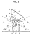
- Figure 1 shows an autonomous lighting terminal 1 according to the invention.
- a device 2 for converting solar energy into electrical energy comprising in the nonlimiting example of the description, a set 3 of photovoltaic cells whose receiving surface 4 is likely to be oriented towards the Sun.
- the assembly 3 is mounted in leaktight manner on a cradle 5, the bottom plate 6 of which is curved according to an arc of circle, center 7.
- the cradle 5 rests on a column 8 of circular section, the top 9 of which matches the shape of the bottom 6; the cradle 5 is fixed to the column 8 by conventional means not shown; this attachment can be final, or preferably carried out by means of articulation means 120, shown in dotted lines.
- the device 2 is capable of a rotational movement, around the center 7 according to an arrow 10, which allows its orientation.
- a sensor 11 consisting of a light-sensitive cell, intended to sense the ambient light level, is embedded in column 8.
- the latter comprises around its entire periphery, a wall 12 transparent to light; this light, concentrated in at least two layers A ', B' of different directions A, B, is produced by an optical unit 18 to which this wall 12 serves as protection against bad weather.
- the optical unit 18, shown diagrammatically, constitutes a first nonlimiting version, visible through an opening made in the drawing of the wall 12.
- This optical unit notably includes a light source 20 which, in the example described is a pseudo-point source 14, located in a reflecting means R in which this source is maintained by conventional means not shown.
- a light source 20 which, in the example described is a pseudo-point source 14, located in a reflecting means R in which this source is maintained by conventional means not shown.
- the reflecting means R consists of the assembly of two reflectors 22, 23, of frustoconical shape for example or as shown in FIG. 1, pseudo parabolic, joined by their top 24, 25, and centered around a longitudinal axis yy; the pseudo-point source 14 being centered on this axis yy at the intersection thereof with an axis ZZ, at the level of which the junction of the reflectors 22, 23 is effected.
- the light flux emitted by the pseudo-point source 14 is shared between the reflectors 22, 23, and concentrated by these in light layers A ', B', projected in directions represented by the arrows A and B.
- This arrangement is remarkable in that it allows, thanks to the reflecting means R, comprising two reflectors 22, 23 communicating through their apex 24, 25, to concentrate the light flow in at least two layers A ', B' of directions A , B by lighting only previously determined areas.
- Such a reflecting means may also include reflectors 22, 23 oriented differently, making it possible to concentrate the light in layers A ', B', of direction A, Al, A2 ... AN for one and B, Bl, B2 , B ... N for the other, so as to favor for example the lighting of the ground 26 on which the autonomous terminal 1 is placed.
- a lower level 13 of column 8 contains first means 100 and possibly second electronic control means 150, a device 15 of accumulators, shown in dotted lines and described in a later phase of the description.
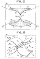
- FIG. 2 shows an optical unit 18, comprising a light source 20 also consisting of a pseudo-point source 14, associated with another version of the reflecting means R.
- the latter consists of two parts 16, 27; the pseudo-point source 14, maintained by conventional means not shown, is centered on an axis Z-Z, between a surface 28 of revolution which comprises the part 16, and another surface 29 of revolution, which comprises the part 27.
- an optical unit 18 comprising as a light source 20, a so-called linear source, consisting of a fluorescent tube 19, associated with a third version of a reflecting means R.
- this reflecting means consists of 4 cylindrical surfaces 33, 34, 35, 36, reflecting light, and assembled in pairs on either side of the tube 19;
- the surfaces 33, 34, on the one hand and 35, 36 on the other hand constitute two pseudo-parabolic cylinders of length L substantially equal to that of the tube 19, and the guidelines of which are formed by the extension of the curves which constitute the edges 39, 40 on the one hand and 41, 42 on the other.
- the light flux emitted in operation by the tube 19 is concentrated and divided into two layers, each projected in a different direction, represented by the arrows A, B, these directions being transverse to the axis V-V.
- this reflector device 18 can be arranged by a modification of the curves which constitute the edges 39, 40, 41, 42, so as to project the light layers in directions.
- FIG. 4 represents in the form of functional blocks, essential elements which constitute an autonomous terminal 1 according to the invention.
- the device 2 connected to the regulator 44, generates a current Il controlled and regulated by the regulator 44; this delivers a current in the form of a current 12, to the device 15 of accumulators to which it is connected, this current 12 constituting the charging current of the device 15.
- This device 15 is connected to the second regulator 46, to which it provides a discharge current 13, which this regulator controls and regulates in order to distribute it in the form of a current 14, to the converter 47 to which it is connected.
- the converter 47 connected to the optical unit 18, has the function of transforming the direct current 14, into an alternating current 15, under a voltage and at a frequency suitable for the ignition of the light source 20 (not shown) contained in the optical unit 18.
- the second condition is linked to the lighting autonomy of the autonomous terminal 1: the current Il, used to charge the accumulators 15, is generated during daylight hours when lighting is not necessary; also the regulator 46, connected to the comparator 45, receives from the latter a command CI authorizing the establishment of the current 13.
- This command CI is obtained by the cooperation between the sensor 11 and the comparator 45.
- the sensor 11 supplies an electrical level E, a function of the ambient brightness, to the comparator 45 to which it is connected; this comparator compares the level E with a predetermined level, constituting a predetermined threshold S.
- the comparator 45 delivers to the regulator 46 a command CI which disappears when the level E becomes higher than the Threshold S.
- second means 150 are provided, intended to achieve a control of the orientation of the device 2.
- This new orientation causes a variation of the current Il, the new value VI of which is compared with the stored value VM, by the comparator 53. If this value V1 is less than VM, the comparator 53 interrupts the command C3 and delivers to the motor means 50 , a command C4 which causes a rotation of the device 2 in a direction opposite to the first.
- This last orientation leads to a new value V2 of the current Il, greater than the value VM stored; the comparator then authorizes a memorization VM of the value V2, and maintains the command C4.
- Each new value V ... VN is also stored, until the comparator 53 detects that it is lower than that stored. The comparator then interrupts the command C4, the orientation of the device 2 being close to the optimum.
- This operation is repeated at each signal SY delivered by the clock device 54.
- the comparator 53 is also connected to the sensor 11; it receives the level E therefrom, corresponding to the level of the ambient luminosity, and compares this level E with a predetermined level, constituting a threshold S2. If the level E is greater than the threshold S2, the comparator 53 authorizes the operation of the servo-control; if the level E is lower than the threshold S2, the control is not carried out.
- This combination of means makes it possible to achieve a simple and effective control of the orientation of the device 2 which makes it possible to increase the autonomy of a lighting bollard according to the invention; the average power supplied by the device 2, being increased by the orientation of the latter towards the sun.
- the autonomy as well as the comfort of use, are also improved thanks to the lighting or extinction control, produced by twilight control.
- an autonomous lighting terminal 1 in accordance with the invention operates using an energy source directly converting solar energy into electrical energy, such as the device 2.
- this autonomous terminal 1 allows autonomy and satisfactory lighting, thanks to the particular arrangement of the optical unit 18; this arrangement makes it possible to reduce the energy consumption in significant proportions, while retaining the concept of satisfactory ambient lighting.
Abstract
Description
L'invention concerne une borne autonome d'éclairage en plein air, de lieux publiques ou privés.The invention relates to an autonomous outdoor lighting bollard, in public or private places.
L'installation d'un moyen d'éclairage, quand la source d'énergie n'existe pas à proximité immédiate, est souvent fort couteuse ; une part importante de ce cout est due notamment aux travaux nécessités par la pose des cables d'alimentation électriques. Aussi, il est avantageux de faire appel à une source d'énergie stockée à proximité ou dans l'installation ; des batteries d'accumulateurs sont ainsi utilisées, mais qui posent le problème de leur recharge.The installation of a means of lighting, when the source of energy does not exist in the immediate vicinity, is often very expensive; a significant part of this cost is due in particular to the work required by laying the electrical power cables. Also, it is advantageous to use a source of energy stored nearby or in the installation; accumulator batteries are thus used, but which pose the problem of recharging them.
Il est connu d'utiliser pour des moyens d'éclairage comportant des accumulateurs, des moyens convertisseurs de l'énergie solaire en énergie électrique servant à recharger ces accumulateurs ; ces moyens sont constitués par exemple, par des éléments sensibles à la lumière, tels que des cellules photovoltaïques.It is known to use, for lighting means comprising accumulators, means converting solar energy into electrical energy used to recharge these accumulators; these means are constituted, for example, by elements sensitive to light, such as photovoltaic cells.
Malheureusement ces cellules sont d'un prix élevé, qui oblige à les utiliser en faible surface, et la quantité d'électricité qu'elles fournissent reste alors relativement faible ; de ce fait, leur application reste généralement limitée à des moyens d'éclairage intermittents.Unfortunately, these cells are of a high price, which means that they have to be used in small areas, and the quantity of electricity they supply then remains relatively low; therefore, their application is generally limited to intermittent lighting means.
Ainsi à titre d'exemple, un ensemble de cellules photovoltaïques, dont la surface est de 0,25m2, fournit une puissance d'environ 30W, dans de bonnes conditions d'éclairage par le soleil. Ces conditions peuvent varier considérablement en cours de journée, et l'énergie suceptible d'être stockée par des accumulateurs, permet une autonomie d'éclairage d'environ une nuit, à condition de limiter à une dizaine de watts la puissance de la source de lumière.Thus, for example, a set of photovoltaic cells, the surface of which is 0.25m2, provides a power of around 30W, in good conditions of lighting by the sun. These conditions can vary considerably during the day, and the energy capable of being stored by accumulators allows a lighting autonomy of approximately one night, provided that the power of the source of light is limited to ten watts. light.
Compte tenu de cette puissance relativement faible, l'exploitation de l'énergie lumineuse qui en résulte, doit être optimisée.Given this relatively low power, the exploitation of the resulting light energy must be optimized.
La présente invention concerne une borne d'éclairage autonome, dont la source d'énergie, est un dispositif convertisseur direct de l'énergie solaire en énergie électrique, permettant d'éclairer avec une intensité normale, des lieux tels que par exemple des parties de jardin ou de chemin.The present invention relates to an autonomous lighting bollard, the energy source of which is a device which converts solar energy directly into electrical energy, making it possible to illuminate with normal intensity places such as, for example, parts of garden or path.
Grace à son agencement, une telle borne d'éclairage, bien que mettant en oeuvre un convertisseur direct de l'énergie solaire en électricité, dispose d'une autonomie suffisante tout en conservant la qualité d'un élairage ambiant, en concentrant l'énergie lumineuse disponible vers des zones préférées.Thanks to its arrangement, such a lighting terminal, although using a direct converter of solar energy into electricity, has sufficient autonomy while retaining the quality of ambient lighting, by concentrating energy light available to preferred areas.
Selon l'invention, une borne autonome d'éclairage comportant un dispositif convertisseur de l'énergie solaire en énergie électrique, un dispositif d'accumulateurs ; est caractérisé en ce que ces dispositifs coopérent avec des premiers moyens électroniques de commande, pour alimenter un bloc optique constitué par une source de lumière et au moins un moyen réflechissant, concentrant la lumière sous forme de nappes dans différentes zones délimitées.According to the invention, an autonomous lighting terminal comprising a device for converting solar energy into electrical energy, an accumulator device; is characterized in that these devices cooperate with first electronic control means, for supplying an optical unit constituted by a light source and at least one reflecting means, concentrating the light in the form of sheets in different delimited areas.
L'invention sera mieux comprise à la lecture de la description qui suit et des cinq figures annexées, parmis lesquelles :
- - la figure 1 représente une borne autonome selon l'invention,
- - les figures 2 et 3 représente des variantes d'un bloc optique,
- - la figure 4 montre le schéma par blocs fonctionnels, d'éléments constituant une borne autonome conforme à l'invention.
- - La figure 5 montre le schéma par blocs fonctionnels des moyens représentés sur la figure 4, associés à des moyens d'asservissement.
- FIG. 1 represents an autonomous terminal according to the invention,
- FIGS. 2 and 3 represent variants of an optical unit,
- - Figure 4 shows the diagram by functional blocks, of elements constituting an autonomous terminal according to the invention.
- - Figure 5 shows the block diagram of the means shown in Figure 4, associated with servo means.
La figure 1 montre une borne autonome 1 d'éclairage conforme à l'invention.Figure 1 shows an
On trouve à un niveau supérieur, un dispositif 2 convertisseur de l'énergie solaire en énergie électrique, comportant dans l'exemple non limitatif de la description, un ensemble 3 de cellules photovoltaïques dont la surface réceptrice 4 est suceptible d'être orientée vers le soleil. L'ensemble 3 est monté de manière étanche sur un berceau 5, dont la plaque de fond 6 est courbée selon un arc de cercle, de centre 7. Le berceau 5 repose sur une colonne 8 de section circulaire, dont le sommet 9 épouse la forme du fond 6 ; le berceau 5 est fixé à la colonne 8 par des moyens classiques non représentés ; cette fixation peut être définitive, où de préférence réalisée par l'intermédiaire de moyens d'articulation 120, représentés en traits pointillés.At a higher level, there is a device 2 for converting solar energy into electrical energy, comprising in the nonlimiting example of the description, a
Par ces moyens d'articulation 120, le dispositif 2 est capable d'un mouvement de rotation, autour du centre 7 selon une flèche 10, qui permet sont orientation. Un capteur 11, constitué d'une cellule sensible à la lumière, destiné à capter le niveau de luminosité ambiant, est encastré dans la colonne 8.By these articulation means 120, the device 2 is capable of a rotational movement, around the center 7 according to an
A un niveau intermédiaire de la colonne 8, celle-ci comporte sur tout son pourtour, une paroi 12 transparente à la lumière ; cette lumière, concentrée dans au moins deux nappes A', B' de directions différentes A, B, est produite par un bloc optique 18 auquel cette paroi 12 sert de protection aux intempéries.At an intermediate level of the
Le bloc optique 18, représenté schématiquement, constitue une première version non limitative, visible grâce à une ouverture pratiquée dans le dessin de la paroi 12.The
Ce bloc optique comporte notamment une source de lumière 20 qui, dans l'exemple décrit est une source pseudo ponctuelle 14, située dans un moyen réfléchissant R dans lequel cette source est maintenue par des moyens classiques non représentés.This optical unit notably includes a
Le moyen réfléchissant R est constitué par l'assemblage de deux réflecteurs 22, 23, de forme par exemple tronconique ou ainsi que montré sur la figure 1, pseudo parabolique, réunis par leur sommet 24, 25, et centrés autour d'un axe longitudinal y-y ; la source pseudo ponctuelle 14 étant centrée sur cet axe y-y à l'intersection de celui-ci avec un axe Z-Z, au niveau duquel est effectuée la jonction des réflecteurs 22, 23. En fonctionnement le flux de lumière émis par la source pseudo ponctuelle 14 est partagé entre les réflecteurs 22, 23, et concentré par ceux-ci dans des nappes de lumières A', B', projetés dans des directions représentées par les flèches A et B.The reflecting means R consists of the assembly of two
Cette disposition est remarquable en ce qu'elle permet grâce à au moyen réfléchissant R, comportant deux réflecteurs 22, 23 communicant par leur sommet 24, 25, de concentrer le flux de lumière dans au moins deux nappes A', B' de directions A, B en n'éclairant que des zones préalablement déterminées.This arrangement is remarkable in that it allows, thanks to the reflecting means R, comprising two
Un tel moyen réflechissant peut également comporter des réflecteurs 22, 23 orientés différemment, permettant de concentrer la lumière dans des nappes A', B', de direction A, Al, A2...AN pour l'une et B, Bl, B2, B...N pour l'autre, de manière à favoriser par exemple l'éclairage du sol 26 sur lequel est posé la borne autonome 1.Such a reflecting means may also include
Un niveau inférieur 13 de la colonne 8, contient des premiers moyens 100 et éventuellement des seconds moyens 150 électroniques de commande, un dispositif 15 d'accumulateurs, représentés en traits pointillés et décrits dans une phase ultérieure de la description.A
La figure 2 montre un bloc optique 18, comportant une source de lumière 20 également constituée d'une source pseudo ponctuelle 14, associée à une autre version du moyen réfléchissant R.FIG. 2 shows an
Dans l'exemple non limitatif de la description, ce dernier est constitué de deux parties 16, 27 ; la source pseudo ponctuelle 14, maintenue par des moyens classiques non représentés, est centrée sur un axe Z-Z, entre une surface 28 de révolution que comporte la partie 16, et une autre surface 29 de révolution, que comporte la partie 27.In the nonlimiting example of the description, the latter consists of two
Ces deux surfaces 28, 29 réfléchissantes de la lumière, sont obtenues chacunes par la rotation autour de l'axe Z-Z de révolution, de la courbe 30 et de la courbe 31.These two
Ces deux surfaces forment ainsi un pseudo paraboloïde de révolution, grâce auquel le flux de lumière émis par la source pseudo ponctuelle 14 est concentré dans une nappe n, projetée sur 360° autour du bloc optique 18 et de son axe Z-Z.These two surfaces thus form a pseudo-paraboloid of revolution, thanks to which the light flux emitted by the
On trouve dans la figure 3, un bloc optique 18 comportant comme source de lumière 20, une source dite linéaire, constituée d'un tube fluorescent 19, associée à une troisième version d'un moyen réfléchissant R.In FIG. 3, there is an
Dans l'exemple non limitatif décrit, ce moyen réfléchissant est constitué par 4 surfaces cylindriques 33, 34, 35, 36, réfléchissant la lumière, et assemblées deux à deux de part et d'autre du tube 19 ;In the nonlimiting example described, this reflecting means consists of 4
Ces surfaces sont réunies sur des axes (non représentés) parallèle à l'axe longitudinal V-V du tube 19 et alignés sur l'axe ZI-Z1 de ce dernier.These surfaces are joined on axes (not shown) parallel to the longitudinal axis V-V of the
Les surfaces 33, 34, d'une part et 35, 36 d'autre part, constituent deux cylindres pseudo paraboliques de longueur L sensiblement égale à celle du tube 19, et dont les directrices sont constituées par le prolongement des courbes que constituent les bords 39, 40 d'une part et 41, 42 d'autre part.The
Le flux lumineux émis en fonctionnement par le tube 19, est concentré et partagé en deux nappes, projetées chacune dans une direction différente, représentée par les flèches A, B, ces directions étant transversales à l'axe V-V.The light flux emitted in operation by the
De même qu'il a été déjà mentionné pour les autres dispositifs réflecteur, ce dispositif réflecteur 18 peut être agencé par une modification des courbes que constituent les bords 39, 40, 41, 42, de manière à projeter les nappes de lumière dans des directions telles que par exemple des directions A, Al, A2...AN pour l'une de ces nappes et B, BI, B2...BN pour l'autre.As already mentioned for the other reflector devices, this
Le schéma de la figure 4 représente sous une forme de blocs fonctionnels, des éléments essentiels qui constituent une borne autonome 1 selon l'invention.The diagram of FIG. 4 represents in the form of functional blocks, essential elements which constitute an
On y trouve
- - le dispositif 2 convertisseur direct de l'énergie solaire en électricité.
- - des
premiers moyens 100 électroniques de commande, figurés dans un cadre en traits pointillés, - - un
dispositif 15 d'accumulateurs, - - un
capteur 11 sensible à la lumière ambiante, - - un bloc optique 18.
- - device 2 direct converter of solar energy into electricity.
- first electronic control means 100, shown in a frame in dotted lines,
- a
device 15 for accumulators, - a
sensor 11 sensitive to ambient light, - - an
optical unit 18.
Le dispositif 2, relié au régulateur 44, génere un courant Il controlé et régulé par le régulateur 44 ; celui-ci délivre un courant sous la forme d'un courant 12, au dispositif 15 d'accumulateurs auquel il est relié, ce courant 12 constituant le courant de charge du dispositif 15. Ce dispositif 15 est relié au second régulateur 46, auquel il fournit un courant 13, de décharge que ce régulateur contrôle et régule pour le distribuer sous la forme d'un courant 14, au convertisseur 47 auquel il est relié. Le convertisseur 47, relié au bloc optique 18, a pour fonction de transformer le courant 14 continu, en un courant alternatif 15, sous une tension et a fréquence appropriée à l'allumage de la source de lumière 20 (non représentée) contenue dans le bloc optique 18.The device 2, connected to the regulator 44, generates a current Il controlled and regulated by the regulator 44; this delivers a current in the form of a current 12, to the
Le courant 13, servant à la production de lumière, est autorisé par le régulateur 46 sous deux conditions :
- - la première condition qu'il contrôle lui-même, est que le niveau du
courant 13 reste suffisant, montrant ainsi un niveau suffisant de la charge des accumulateurs 15 ; ceci dans le but de maintenir la longévité de ces accumulateurs.
- - The first condition that it controls itself, is that the level of current 13 remains sufficient, thus showing a sufficient level of the charge of
accumulators 15; this in order to maintain the longevity of these accumulators.
La seconde condition est liée à l'autonomie d'éclairage de la borne autonome 1 : le courant Il, servant à la charge des accumulateurs 15, est généré pendant les heures de jour où l'éclairage n'est pas nécessaire ; aussi le régulateur 46, relié au comparateur 45, reçoit de ce dernier une commande CI autorisant l'établissement du courant 13.The second condition is linked to the lighting autonomy of the autonomous terminal 1: the current Il, used to charge the
Cette commande CI est obtenue par la coopération entre le capteur 11 et le comparateur 45. Le capteur 11 fournit un niveau électrique E, fonction de la luminosité ambiante, au comparateur 45 auquel il est relié ; ce comparateur compare le niveau E a un niveau prédéterminé, constituant un seuil S prédéterminé. Quand le niveau E est inférieur au seuil S, le comparateur 45 délivre au régulateur 46 une commande CI qui disparait quand le niveau E devient supérieur au Seuil S.This command CI is obtained by the cooperation between the
Ceci constitue une commande crépusculaire grâce a laquelle, l'éclairage par une borne autonome 1 selon l'invention est établi et coupé automatiquement, en fonction de la luminosité ambiante.This constitutes a twilight control by means of which the lighting by an
Comme le montre la figure 5, outre les moyens déjà représentés sur la figure 4, des seconds moyens 150 sont prévus, destinés a réaliser un asservissement de l'orientation du dispositif 2.As shown in FIG. 5, in addition to the means already shown in FIG. 4, second means 150 are provided, intended to achieve a control of the orientation of the device 2.
Ces moyens 150, montrés dans un cadre en traits pointillés comportent :
- - des moyens moteurs 50 coopérant avec les moyens d'articulation 120 (figure 1), cette coopération étant symbolisée par une ligne en traits pointillés LM.
- - un comparateur 53 des valeurs V,...VN que peut atteindre le courant Il.
- - un dispositif de mémorisation 52 des valeurs V...VN
- -
un dispositif horloge 54, générateur à intervales de temps prédéterminés, de signaux SY.
- - Motor means 50 cooperating with the articulation means 120 (FIG. 1), this cooperation being symbolized by a line in dotted lines LM.
- - a comparator 53 of the values V, ... VN which the current Il can reach.
- - a storage device 52 for the values V ... VN
- - A
clock device 54, generator with predetermined time intervals, of SY signals.
Ainsi qu'il a été précédemment expliqué, le régulateur 44 contrôle le courant Il et, étant relié au comparateur 53 et au dispositif de mémorisation 52, il transmet à ces derniers les valeurs V...VN que possède le courant Il ; d'autre part, l'horloge 54 délivre, avec des intervales de temps prédéterminés, des signaux SY au comparateur 53. A réception d'un signal SY au comparateur, celui-ci étant relié au dispositif de mémorisation 52, dans un premier temps :
- - délivre à ce dernier une commande AM, l'autorisant a effectuer une mémorisation de la valeur V...VN que possède à cet instant le courant Il ; cette valeur mémorisée VM, transmise par le dispositif de mémorisation au comparateur 53, est lue en permanence par ce dernier, et lui sert de niveau de référence.
- - dans un deuxième temps, le comparateur 53 délivre une commande C3 aux moyens moteurs 50, provoquant une rotation dans un premier sens déterminé du dispositif 2, qui entraine une modification de l'orientation de ce dernier.
- - issues an AM command to the latter, authorizing it to store the value V ... VN that the current Il has at this instant; this stored value VM, transmitted by the storage device to the comparator 53, is permanently read by the latter, and serves as its reference level.
- - In a second step, the comparator 53 delivers a command C3 to the motor means 50, causing a rotation in a first determined direction of the device 2, which causes a modification of the orientation of the latter.
Cette nouvelle orientation entraine une variation du courant Il, dont la nouvelle valeur VI est comparée à la valeur mémorisée VM, par le comparateur 53. Si cette valeur V1 est inférieure à VM, le comparateur 53 intérrompt la commande C3 et délivre aux moyens moteurs 50, une commande C4 qui provoque une rotation du dispositif 2 dans un sens contraire au premier. Cette dernière orientation entraine une nouvelle valeur V2 du courant Il, supérieure à la valeur VM mémorisée ; le comparateur autorise alors une mémorisation VM de la valeur V2, et maintient la commande C4.This new orientation causes a variation of the current Il, the new value VI of which is compared with the stored value VM, by the comparator 53. If this value V1 is less than VM, the comparator 53 interrupts the command C3 and delivers to the motor means 50 , a command C4 which causes a rotation of the device 2 in a direction opposite to the first. This last orientation leads to a new value V2 of the current Il, greater than the value VM stored; the comparator then authorizes a memorization VM of the value V2, and maintains the command C4.
Chaque nouvelle valeur V...VN est aussi mémorisée, jusqu'au moment ou le comparateur 53 détecte qu'elle est inférieure à celle mise en mémoire. Le comparateur interromps alors la commande C4, l'orientation du dispositif 2 étant voisine de l'optimum.Each new value V ... VN is also stored, until the comparator 53 detects that it is lower than that stored. The comparator then interrupts the command C4, the orientation of the device 2 being close to the optimum.
Ce fonctionnement est répété à chaque signal SY délivré par le dispositif horloge 54.This operation is repeated at each signal SY delivered by the
Le comparateur 53 est également relié au capteur 11 ; il en reçoit le niveau E, correspondant au niveau de la luminosité ambiante, et compare ce niveau E à un niveau prédéterminé, constituant un seuil S2. Si le niveau E est supérieur au seuil S2, le comparateur 53 autorise le fonctionnement de l'asservissement ; si le niveau E est inférieur au seuil S2, l'asservissement n'est pas éffectué.The comparator 53 is also connected to the
Ceci permet de limiter l'exercice de cet asservissement aux périodes de jour.This limits the exercise of this enslavement to day periods.
Cette combinaison de moyens permet de réaliser un asservissement de l'orientation du dispositif 2 simple et efficace qui permet d'augmenter l'autonomie d'une borne d'éclairage conforme a l'invention ; la puissance moyenne fournie par le dispositif 2, étant accrue par l'orientation de ce dernier vers le soleil.This combination of means makes it possible to achieve a simple and effective control of the orientation of the device 2 which makes it possible to increase the autonomy of a lighting bollard according to the invention; the average power supplied by the device 2, being increased by the orientation of the latter towards the sun.
Cette orientation est soit manuelle, soit automatique par cet asservissement obtenu notamment grâce :
- - à la coopération entre le comparateur 53 et le régulateur 44, qui permet d'utiliser le courant Il généré par le dispositif 2 pour définir l'orientation de celui-ci.
- - en ce que la coopération entre le régulateur 44 et les moyens 150 s'effectue des intervales de temps prédéterminés, grâce à
un dispositif d'horloge 54 que comporte les moyens 150. - - à la coopération entre le capteur 11 et le comparateur 53, qui permet de déterminer les périodes ou cet asservissement s'exerce.
- - the cooperation between the comparator 53 and the regulator 44, which makes it possible to use the current II generated by the device 2 to define the orientation of the latter.
- - in that the cooperation between the regulator 44 and the
means 150 takes place at predetermined time intervals, thanks to aclock device 54 that themeans 150 comprises. - - the cooperation between the
sensor 11 and the comparator 53, which makes it possible to determine the periods in which this control is exercised.
L'autonomie ainsi que le confort d'utilisation, sont également améliorés grâce àla commande d'éclairage ou d'extinction, produite par la commande crépusculaire.The autonomy as well as the comfort of use, are also improved thanks to the lighting or extinction control, produced by twilight control.
Ainsi qu'elle à été précédemment décrite, une borne autonome 1 d'éclairage conforme à l'invention, fonctionne à l'aide d'une source d'énergie convertissant directement l'énergie solaire en énergie électrique, telle que le dispositif 2.As previously described, an
Malgré la puissance relativement faible que délivre cette source, cette borne autonome 1 permet une autonomie et un éclairage satisfaisant, grâce à l'agencement particulier du bloc optique 18 ; cet agencement permet de réduire la consommation d'énergie dans des proportions importantes, tout en conservant la notion d'éclairage ambiant satisfaisant.Despite the relatively low power delivered by this source, this
Claims (12)
Applications Claiming Priority (2)
| Application Number | Priority Date | Filing Date | Title |
|---|---|---|---|
| FR8120862A FR2516204A1 (en) | 1981-11-06 | 1981-11-06 | AUTONOMOUS LIGHTING TERMINAL |
| FR8120862 | 1981-11-06 |
Publications (1)
| Publication Number | Publication Date |
|---|---|
| EP0079267A1 true EP0079267A1 (en) | 1983-05-18 |
Family
ID=9263779
Family Applications (1)
| Application Number | Title | Priority Date | Filing Date |
|---|---|---|---|
| EP82401981A Withdrawn EP0079267A1 (en) | 1981-11-06 | 1982-10-26 | Self-contained post-mounted lighting fixture |
Country Status (2)
| Country | Link |
|---|---|
| EP (1) | EP0079267A1 (en) |
| FR (1) | FR2516204A1 (en) |
Cited By (5)
| Publication number | Priority date | Publication date | Assignee | Title |
|---|---|---|---|---|
| WO1993009378A1 (en) * | 1991-11-04 | 1993-05-13 | Solar Wide Industrial Ltd. | Solar panel unit and solar lamp including same |
| GB2421784A (en) * | 2005-01-04 | 2006-07-05 | Feng-Nien Lee | Solar Powered Light with Water sprayer |
| USD743607S1 (en) * | 2014-03-24 | 2015-11-17 | Koninklijke Philips N.V. | Lamp |
| CN108361636A (en) * | 2018-03-14 | 2018-08-03 | 陈安娜 | A kind of safe macromolecule light conversion agent device |
| CN109058893A (en) * | 2018-08-02 | 2018-12-21 | 蒙城县望槐信息科技有限责任公司 | A kind of energy conservation and environmental protection lighting apparatus based on new energy |
Citations (7)
| Publication number | Priority date | Publication date | Assignee | Title |
|---|---|---|---|---|
| FR1057616A (en) * | 1952-06-03 | 1954-03-09 | Multiple parabolic surface reflector | |
| FR1072116A (en) * | 1952-03-04 | 1954-09-08 | Philips Nv | Incandescent lamp with reflector |
| FR1158927A (en) * | 1956-10-01 | 1958-06-20 | Method and device for increasing the brightness of dark rooms | |
| FR1358378A (en) * | 1962-09-27 | 1964-04-17 | Ind Mecanique Et Automobile S | Multi-function lighting device |
| FR2353091A1 (en) * | 1976-05-26 | 1977-12-23 | Massachusetts Inst Technology | SOLAR RADIATION COLLECTOR |
| US4200904A (en) * | 1978-04-14 | 1980-04-29 | Duc Doan | Solar powered street lighting system |
| US4281369A (en) * | 1978-12-11 | 1981-07-28 | Batte Christopher L | Method and apparatus for solar power lighting |
-
1981
- 1981-11-06 FR FR8120862A patent/FR2516204A1/en not_active Withdrawn
-
1982
- 1982-10-26 EP EP82401981A patent/EP0079267A1/en not_active Withdrawn
Patent Citations (7)
| Publication number | Priority date | Publication date | Assignee | Title |
|---|---|---|---|---|
| FR1072116A (en) * | 1952-03-04 | 1954-09-08 | Philips Nv | Incandescent lamp with reflector |
| FR1057616A (en) * | 1952-06-03 | 1954-03-09 | Multiple parabolic surface reflector | |
| FR1158927A (en) * | 1956-10-01 | 1958-06-20 | Method and device for increasing the brightness of dark rooms | |
| FR1358378A (en) * | 1962-09-27 | 1964-04-17 | Ind Mecanique Et Automobile S | Multi-function lighting device |
| FR2353091A1 (en) * | 1976-05-26 | 1977-12-23 | Massachusetts Inst Technology | SOLAR RADIATION COLLECTOR |
| US4200904A (en) * | 1978-04-14 | 1980-04-29 | Duc Doan | Solar powered street lighting system |
| US4281369A (en) * | 1978-12-11 | 1981-07-28 | Batte Christopher L | Method and apparatus for solar power lighting |
Cited By (7)
| Publication number | Priority date | Publication date | Assignee | Title |
|---|---|---|---|---|
| WO1993009378A1 (en) * | 1991-11-04 | 1993-05-13 | Solar Wide Industrial Ltd. | Solar panel unit and solar lamp including same |
| US5467257A (en) * | 1991-11-04 | 1995-11-14 | Solar Wide Industrial Ltd. | Solar panel unit and solar lamp including same |
| GB2421784A (en) * | 2005-01-04 | 2006-07-05 | Feng-Nien Lee | Solar Powered Light with Water sprayer |
| USD743607S1 (en) * | 2014-03-24 | 2015-11-17 | Koninklijke Philips N.V. | Lamp |
| CN108361636A (en) * | 2018-03-14 | 2018-08-03 | 陈安娜 | A kind of safe macromolecule light conversion agent device |
| CN108361636B (en) * | 2018-03-14 | 2019-01-18 | 江苏星光新材料科技有限公司 | A kind of safe macromolecule light conversion agent device |
| CN109058893A (en) * | 2018-08-02 | 2018-12-21 | 蒙城县望槐信息科技有限责任公司 | A kind of energy conservation and environmental protection lighting apparatus based on new energy |
Also Published As
| Publication number | Publication date |
|---|---|
| FR2516204A1 (en) | 1983-05-13 |
Similar Documents
| Publication | Publication Date | Title |
|---|---|---|
| EP1019999B1 (en) | Self-contained recharging device for portable telephone and/or battery and/or protective case | |
| FR3025395B1 (en) | LED LIGHTING DEVICE | |
| EP0652835B1 (en) | Electrically-driven car | |
| FR2487993A1 (en) | ARTIFICIAL LIGHTING ASSEMBLY FOR PHOTOGRAPHIC APPARATUS AND REFLECTOR FOR THIS ASSEMBLY | |
| EP2279373A2 (en) | Portable self-contained photovoltaic solar device | |
| FR2740647A1 (en) | VEHICLE PROJECTOR | |
| EP0079267A1 (en) | Self-contained post-mounted lighting fixture | |
| EP1266268A1 (en) | Watch winding device | |
| EP2504932A1 (en) | Led lighting unit having improved control | |
| EP0265328B1 (en) | Autonomous power supply system | |
| EP3616991A1 (en) | Bicycle-mounted active lighting device device | |
| EP2438586A1 (en) | Display module for vehicles | |
| EP3918640B1 (en) | Device equipped with crystalline silicon photovoltaic cells having surfaces with varied geometries | |
| EP3297902A1 (en) | Vehicle wheel fitted with solar cells | |
| EP0394593B1 (en) | Luminous buoy | |
| FR2945072A1 (en) | Multifunctional energetic occulting system i.e. occulting blind, for window of e.g. office building, has management module supplying portion of energy to illumination unit and another portion of energy to apparatus external to system | |
| FR2654687A1 (en) | ELECTRICAL DEVICE FOR CONTROLLING THE ORIENTATION OF THE LIGHTING PROJECTORS OF A MOTOR VEHICLE. | |
| FR2468940A1 (en) | Voltage regulator for alternator charging vehicle battery - maintains min. voltage through energising winding allowing operation of failure light | |
| FR2672746A3 (en) | Solar charging station | |
| FR2690320A1 (en) | Chair that automatically tracks sun - uses opto-electronic detectors mounted on top of chair back to signal controller that drives motor to rotate chair | |
| FR2466070A3 (en) | BASE FOR ROTATING ADVERTISING DISPLAY | |
| FR2514871A1 (en) | Automatic controller of aim of solar collector - uses microprocessor which computers theoretical aim and generates drive signals to positioning motors | |
| CH715274A2 (en) | Active lighting device portable or placed on a bicycle. | |
| FR2536600A1 (en) | Automatic and stand-alone device whose objective is to continuously set in motion, illuminate and recharge itself. | |
| BE1024209A1 (en) | IMPROVEMENTS IN OR RELATING TO LUMINAIRES |
Legal Events
| Date | Code | Title | Description |
|---|---|---|---|
| PUAI | Public reference made under article 153(3) epc to a published international application that has entered the european phase |
Free format text: ORIGINAL CODE: 0009012 |
|
| AK | Designated contracting states |
Designated state(s): AT BE DE FR GB IT LU NL SE |
|
| STAA | Information on the status of an ep patent application or granted ep patent |
Free format text: STATUS: THE APPLICATION IS DEEMED TO BE WITHDRAWN |
|
| 18D | Application deemed to be withdrawn |
Effective date: 19840413 |
|
| RIN1 | Information on inventor provided before grant (corrected) |
Inventor name: DEPOND, JEAN-MARIE Inventor name: BOUCAUT, ALAIN Inventor name: DIORE, CHRISTIAN Inventor name: SEBILLE, MARC |